

Page 1
OWNER'S MANUAL
4.5" CHIPPERS
Manual PN 14783-00
Rev. 0304
Companion to 14784-00
MODELS
77412
77413
77412S
77413S
Page 2
Before you Begin
DEAR BEAR CAT CUSTOMER,
Thank you for purchasing a Crary Bear Cat product. The Bear Cat line is designed,
tested, and manufactured to give years of dependable performance. To keep your
machine operating at peak efficiency, it is necessary to adjust it correctly and make
regular inspections. The following pages will assist you in the operation and
maintenance of your machine. Please read and understand this manual before
operating.
How to Contact
Bear Cat
A
DDRESS
Crary Bear Cat
If you have any questions or comments about this manual, please call us toll-free at
1-800-247-7335.
If you have any questions or problems with your machine, please call or write your
local factory-authorized Bear Cat dealer.
PLEASE SEND US YOUR WARRANTY CARD
A warranty card is included in your owner's kit packaged with your machine.
Please take the time to fill in the information requested on the card. When you
send your completed card to us, we will register your machine and start your
coverage under our limited warranty.
EMISSION INFORMATION
237 NW 12th Street
PO Box 849
West Fargo, ND
58078
P
HONE
800-247-7335
701-282-5520
Fax: 701-282-9522
E
MAIL
opesales@crary.com
service@crary.com
H
OURS
M-F, 8 a.m. to 5 p.m.
Central Time
WARNING
WARNING TO ALL CALIFORNIA
AND OTHER STATES OPERATING
OUTDOOR POWER EQUIPMENT
Under California Law and under the
laws of several other states you are
not permitted to operate an internal
combustion engine using hydrocarbon
fuels on any forest covered, brush
covered or grass covered land or on
land covered with grain hay or other
flammable agricultural crop, without an
engine spark arrester in continuous
effective working order.
The engine on your power equipment,
like most outdoor power equipment, is
an internal combustion engine that
burns gasoline, a hydrocarbon fuel.
Therefore, your power equipment must
be equipped with a spark arrester
muffler in continuous effective working
order. The spark arrester must be
attached to the engine exhaust system
in such a manner that flames or heat
from the system will not ignite
flammable material.
Failure of the owner/operator of the
equipment to comply with this
regulation is a misdemeanor under
California law, and may also be a
violation of other state and or federal
regulations, laws, ordinances, or
codes. Contact your local fire marshal
or forest service for specific information
about what regulations apply in your
area.
The standard muffler installed on the
engine is not equipped with a spark
arrester. One must be added before
use if this machine is intended to be
used in an area where a spark arrester
is required by law. Contact the local
authorities if these laws apply to you.
See your authorized engine dealer for
spark arrester options.
Page 3

Page 1
4.5" BearCat Chipper Operator's Manual
LIMITED WARRANTY
Crary Bear Cat chippers are warranted one year from the date of sale to the original consumer purchaser and
one year from the date of sale to a commercial or rental operation. The engine is warranted by the original
manufacturer with the terms and limitations listed in the manufacturer's manual.
Within the above stated period, Crary Co. will replace any part(s) found to be defective in material and/or
workmanship, after the receipt of the part in our plant. Labor costs to replace these defective parts will be
paid at a Crary established labor rate and time allowed (flat rate) for repair. All transportation charges
incurred in shipping part(s) are the responsibility of the purchaser.
This warranty is void in the case of accidents, failure to perform normal maintenance, or failure to follow those
instructions listed in the service manual. This warranty is also in lieu of all other expressed warranties and
voids any implied warranty as to the merchantability or fitness of the product for a particular purpose and of
any other obligation on the part of Crary Co. Some states do not allow limitations on how long the implied
warranty lasts, so the above limitation may not apply to you.
This warranty applies only to parts or components which are defective, and does not cover necessary repair
due to normal wear, misuse, accidents, or lack of proper maintenance. This includes but is not limited to
belts, pulleys, bearings, and chipper blades. Regular routine maintenance of the unit to keep it in proper
operating condition is the responsibility of the owner.
All warranty repair reimbursable under the Crary Co. warranty must be performed by an authorized Bear Cat
service dealer using Bear Cat approved replacement parts. Repair or attempted repair by anyone other than
an authorized Bear Cat service dealer, or repairs using parts not approved by Bear Cat are not reimbursable
under the Crary Co. warranty. In addition, these unauthorized repair attempts may result in additional
malfunction, the correction of which is not covered by warranty.
Crary Co. is not liable for indirect, incidental, or consequential damages in connection with the use of this
product including any cost or expense or providing substitute equipment or service during periods of malfunction or non-use.
Some states do not allow the exclusion of incidental or consequential damages, so the above exclusion may
not apply to you. This warranty gives you specific legal rights. You may also have other rights which vary
from state to state.
Be sure to note the chipper serial number in any correspondence with Crary Co. or any authorized Bear Cat
dealer. The serial number is located on the rotor assembly cover.
Crary Company
A Division of TerraMarc Industries
237 12th St. NW • P.O. Box 849
West Fargo, ND 58078-0849
(701)282-5520 • FAX: (701)282-9522
www.bearcatproducts.com
www.terramarc.com
Page 4

Page 2
4.5" BearCat Chipper Operator's Manual
CONTENTS
SECTION DESCRIPTION PAGE
SERIAL NUMBER LOCA TION ....................................................................................................................................3
REPLACEMENT PARTS ............................................................................................................................................ 3
1. SAFETY ................................................................................................................4
1.1 THE SAFETY ALERT SYMBOL ......................................................................................................................... 4
1.2 BEFORE OPERA TING .......................................................................................................................................4
1.3 OPERA TION SAFETY........................................................................................................................................5
1.4 MAINTENANCE AND STORAGE SAFETY ........................................................................................................6
1.5 TOWING SAFETY..............................................................................................................................................6
1.6 BA TTERY SAFETY ............................................................................................................................................6
2. ASSEMBLY...........................................................................................................................................7
2.1 ASSEMBLING THE MACHINE ........................................................................................................................... 7
2.2 ASSEMBLE THE HITCH, AXLE AND WHEELS. ................................................................................................. 8
2.2.1 MODELS 77412, 77412S...................................................................................................................8
2.2.2 MODELS 77413, 77413S...................................................................................................................9
2.3 ATTACH THE CHIPPER DEFLECTOR ............................................................................................................. 10
2.4 ATTACH THE OPTIONAL DISCHARGE TUBE.................................................................................................. 10
2.5 ATTACH THE CHIPPER CHUTE....................................................................................................................... 11
2.6 ATTACH THE CHIPPER CHUTE EXTENSION (S MODELS)............................................................................ 11
2.7 CONNECTING THE BATTERY ......................................................................................................................... 11
3. CONTROLS.......................................................................................................12
3.1 CONTROLS ...................................................................................................................................................... 12
4. OPERA TION......................................................................................................13
4.1 STARTING ELECTRIC MODELS (77412, 77412S) ........................................................................................... 13
4.2 STARTING RECOIL MODELS (77413, 77413S) ............................................................................................... 13
4.3 STOPPING ELECTRIC MODELS (77412, 77412S) .......................................................................................... 14
4.4 STOPPING RECOIL MODELS (77413, 77413S) .............................................................................................. 14
4.5 CHIPPING ........................................................................................................................................................ 14
4.6 HOOKING & UNHOOKING CHIPPER (MODEL 77413, 77413S)...................................................................... 15
5. SERVICE AND MAINTENANCE......................................................................16
5.1 INSTALLING THE DISK LOCK .................................................................................................................. .......16
5.2 SHARPENING CHIPPER BLADES .................................................................................................................. 16
5.3 REPLACING CHIPPING BLADES ....................................................................................................................17
5.4 SETTING CHIPPING BLADE CLEARANCE ..................................................................................................... 17
5.5 ADJUSTING THE DRIVE BELT......................................................................................................................... 17
5.6 REPLACING DRIVE BEL TS ............................................................................................................................. 18
5.7 CLEARING A PLUGGED DISK.........................................................................................................................18
5.8 REPLACING ROTOR BEARINGS. ................................................................................................................... 19
5.9 GREASEABLE BEARINGS.............................................................................................................................. 20
5.10 OTHER SERVICE AND MAINTENANCE TIPS..................................................................................................22
5.11 TRAILER SERVICE TIPS.................................................................................................................................. 22
6. TROUBLESHOOTING ......................................................................................23
6.1 GENERAL TROUBLESHOOTING..................................................................................................................... 23
7. SPECIFICA TIONS.............................................................................................25
7.1 SIZE SPECIFICA TIONS.................................................................................................................................... 25
7.2 BOL T TORQUE................................................................................................................................................. 26
Page 5
Page 3
4.5" BearCat Chipper Operator's Manual
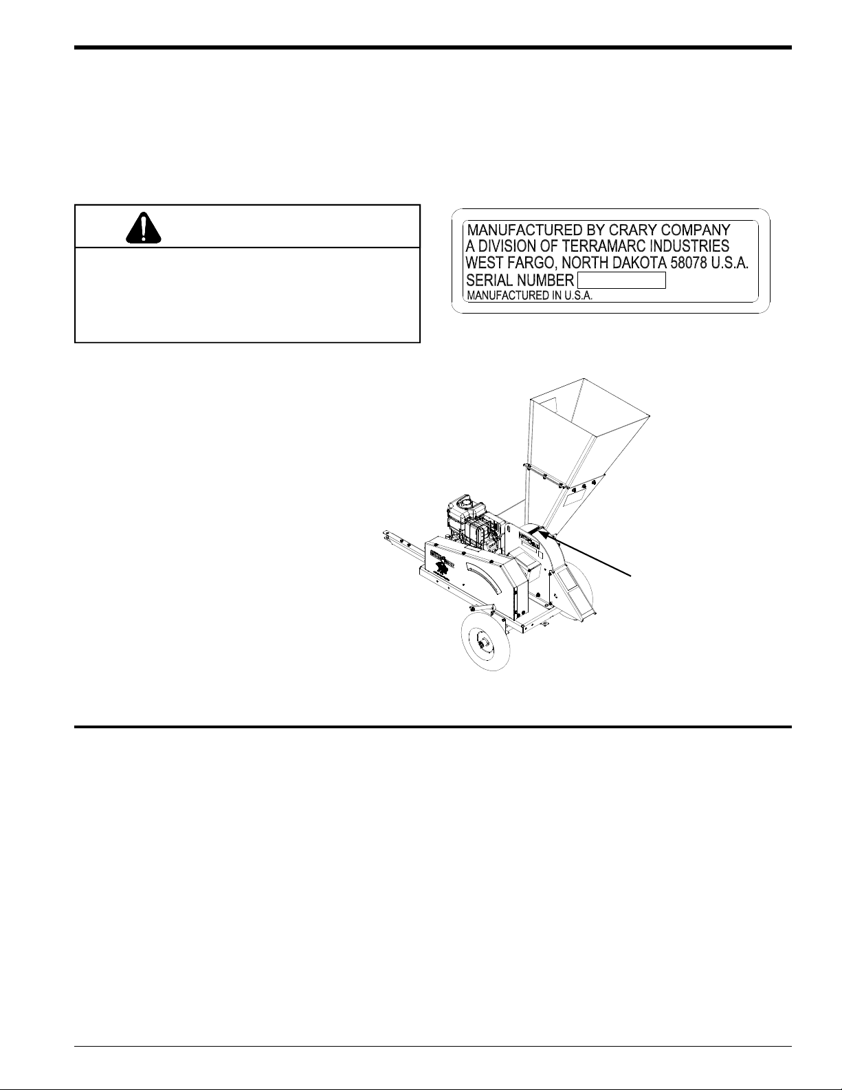
SERIAL NUMBER LOCATION
Always give your dealer the serial number of your Crary Bear Cat product when ordering parts, requesting service or any
other information.
Please record the serial number in the space provided below and on the warranty and registration card. The serial number
is located on the top chipper housing.
WARNING
To prevent personal injury or property damage: Disengage the source providing power to the machine and
make sure that all moving parts have come to a complete stop, before obtaining serial number, servicing,
adjusting or repairing.
Serial Number ___________________
YXXXXX
Serial Number Decal
Serial Number Location
REPLACEMENT PARTS
Only genuine Bear Cat replacement parts should be used to repair the machine. Bear Cat replacement parts are available
from your Bear Cat dealer. To obtain prompt, efficient service, remember to give the dealer the correct part description and
serial number of the machine.
Please be sure to provide the following information:
1. The SERIAL NUMBER of your machine.
2. The PART NUMBER of the part.
3. The PART DESCRIPTION.
4. The QUANTITY needed.
Page 6
Page 4
4.5" BearCat Chipper Operator's Manual
1
Section
Safety
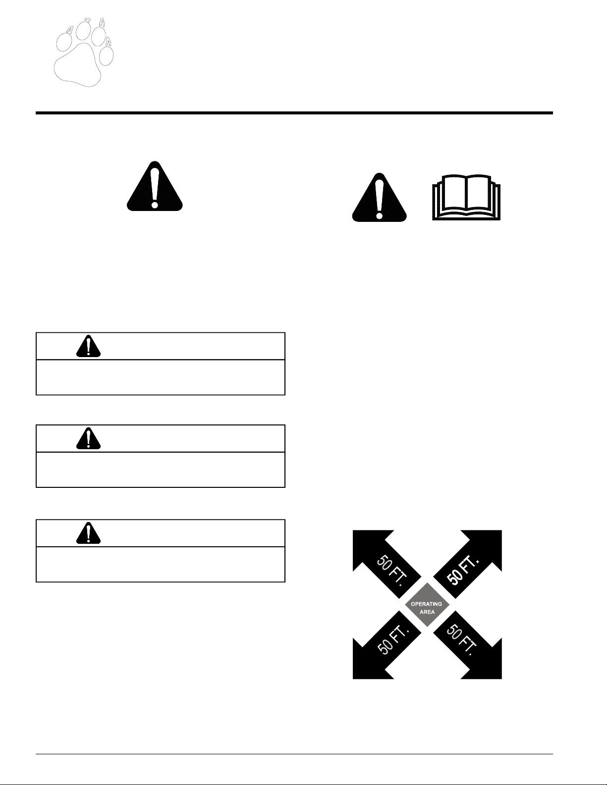
1.1 THE SAFETY ALERT SYMBOL
This is the safety alert symbol. It is used in this Owner /
Operator’s Manual and on your machine to alert you to
potential hazards.
Whenever you see this symbol, read and obey the safety
message that follows it. Failure to obey the safety message
could result in personal injury, death or property damage.
CAUTION
Indicates a potentially hazardous situation that, if not
avoided, may result in minor or moderate injury.
1.2 BEFORE OPERATING
1. Read this Owner / Operator’s manual. Be completely
familiar with the controls and the proper use of this equipment.
2. Before inspecting or servicing any part of the machine,
wait for all parts to stop moving and remove the spark
plug wire. Be aware that rotating parts slow down gradually after power is stopped.
3. Keep safety decals clean and legible. Replace missing
or illegible safety decals.
4. Familiarize yourself with all of the safety and operating
decals on this equipment and on any of it’s attachments
or accessories.
WARNING
Indicates a potentially hazardous situation that, if not
avoided, could result in death or serious injury.
DANGER
Indicates an imminently hazardous situation that, if not
avoided, will result in death or serious injury.
5. Do not allow children or any person unfamiliar with the
use of the unit to use this machine.
6. Keep the area of operation clear of all persons, particu-
larly small children. Keep bystanders at least 50 feet
(15 meters) away from the area of operation.
7. Do not run this equipment in an enclosed area. Do not
Page 7
Page 5
4.5" BearCat Chipper Operator's Manual
SAFETY
operate this equipment in or near buildings, windows, or
air conditioners.
8. If needed, always use an approved fuel container. Keep
open flames, sparks, smoking materials, and other
sources of combustion away from fuel.
9. Do not operate this machine if you are under the influence of alcohol, medications, or substances that can
affect your vision, balance, and judgement. Do not operate if tired or ill. You must be in good health to operate
this machine safely.
10. Wear safety glasses at all times while operating this
machine.
11. Use only in daylight or good artificial light.
12. Never use without proper guards in place.
13. Avoid wearing loose fitting clothing. Never operate this
machine wearing clothing with drawstrings that could
wrap around or get caught in the machine.
14. Check that all screws, nuts, bolts, and other fasteners
are properly secured before starting the machine. Check
all screws, nuts, bolts, and other fasteners for proper
tightness to ensure everything is in proper working condition once every 8 hours of operation.
15. Keep all guards, deflectors, and shields in place and in
good working condition.
16. Do not transport or move machine while the machine is
running.
1.3 OPERATION SAFETY
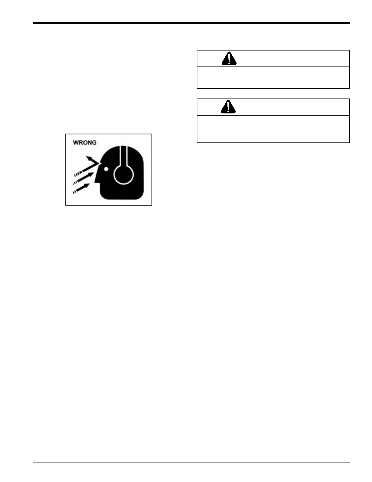
WARNING
Material can kickup or shift suddenly and cause serious
injury or death. Wear eye and hearing protection.
DANGER
Keep hands, feet and clothing out of inlets and discharge
openings while machine is operating to avoid serious
personal injury.
1. Keep your body and clothing away from any moving
part of the machine.
2. Exclude pieces of metal, rocks, bottles, cans, and other
foreign objects from entering the machine.
3. Shut off machine immediately if the cutting mechanism
strikes any foreign object or the machine starts making
an unusual noise or vibrating. Allow the machine to
stop completely. After machine stops:
A. Remove spark plug wire.
B. Inspect for damage.
C. Replace or repair any damaged parts.
D. Check for and tighten any loose parts.
4. Stand clear of the discharge area when operating this
machine.
5. Keep your face and body back from the feed opening.
6. Do not climb on machine when operating. Keep proper
balance and footing at all times.
7. Keep the machine clear of debris and other accumulations.
8. Set up your work site so you are not endangering traffic
and the public. Take great care to provide adequate warnings.
9. Ensure debris does not blow into traffic, parked cars, or
pedestrians.
10. Check the bolts for correct torque every 8 hours of operation (see Section 7.2).
11. If the machine becomes clogged, shut off engine and
allow machine to stop completely before clearing debris.
Page 8
Page 6
4.5" BearCat Chipper Operator's Manual
DANGER / POISON
SAFETY
1.4 MAINTENANCE AND STORAGE
SAFETY
NOTE
Always read and follow the engine owner's manual or
contact the engine manufacturer for engine safety instructions and decals.
1. Disconnect the spark plug wire when this equipment is
stopped for service, inspection, storage, or to change an
accessory.
2. Replace any missing or unreadable safety decals. Refer
to the parts manual for part numbers when ordering safety
decals from an area Bear Cat dealer.
3. Store the machine out of reach of children and where fuel
vapors will not reach an open flame or spark.
4. Allow machine to cool before storing in an enclosure.
5. Drain the fuel and dispose of it in a safe manner for storage periods of three months or more.
1.5 TOWING SAFETY
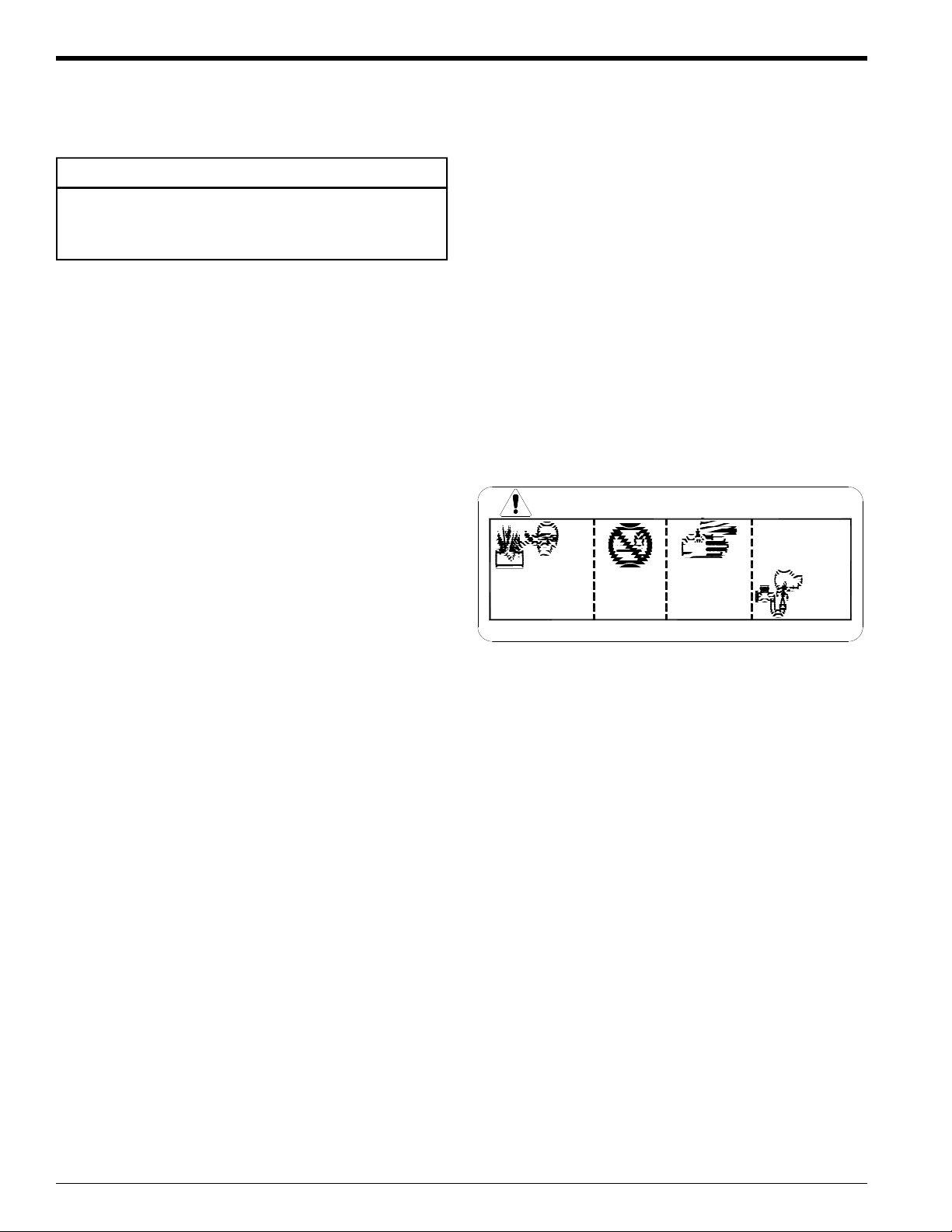
1.6 BATTERY SAFETY
1. Improper use and care of the battery on electric start
models can result in serious personal injury or property
damage. Always observe the following safety precautions:
2. Danger / Poison - Causes Severe Burns. The battery contains sulfuric acid. Avoid contact with skin, eyes or clothing. Keep out of reach of children.
ANTIDOTE-External Contact: Flush immediately
with lots of water.
ANTIDOTE-Internal: Drink large quantities of water
or milk. Follow with milk of magnesia, beaten egg
or vegetable oil. Call a physician immediately.
ANTIDOTE-Eye Contact: Flush with water for 15
minutes. Get prompt medical attention.
FLUSH EYES
IMMEDIATELY
SHIELD EYES
EXPLOSIVE GASES
CAN CAUSE
BLINDNESS OR
INJURY
KEEP OUT OF THE REACH OF CHILDREN. DO NOT TIP. KEEP VENT CAPS TIGHT AND LEVEL.
NO
• SPARKS
• FLAMES
• SMOKING
SULFURIC
ACID
CAN CAUSE
BLINDNESS OR
SEVERE BURNS
WITH WATER
GET
MEDICAL
HELP
FAST
1. Connect hitch safety chains. Tighten and secure trailer
hitch bolts. Do not attempt to tow the trailer if vehicle is
not equipped with the proper size hitch ball.
2. Do not exceed maximum towing speed, as indicated on
the tire sidewall. Inflate tires to manufacturer's specification as stated on the sidewall.
3. Check wheel lug bolts periodically to ensure they are
tight and secure.
4. Never allow passengers to ride on the chipper.
5. If applicable, shut off fuel supply when towing.
3. The battery produces explosive gases. Keep sparks,
flame or cigarettes away. Ventilate area when charging
battery. Always wear safety goggles when working near
battery.
4. The battery contains toxic materials. Do not damage
battery case. If case is broken or damaged, avoid contact with battery contents.
5. Neutralize acid spills with a baking soda and water solution. Properly dispose of a damaged or worn-out battery.
Check with local authorities for proper disposal methods.
6. Do not short circuit battery. Severe fumes and fire can
result.
7. Before working with electrical wires or components, disconnect the negative (-) cable first. Disconnect the positive (+) cable second. Reverse this order when reconnecting battery cables.
Page 9
Page 7
4.5" BearCat Chipper Operator's Manual
2
Section
Assembly
Your chipper may arrive totally or partially assembled.
Perform the steps in this section if your chipper arrives
partially assembled.
NOTE
REFER TO THE PARTS BOOK DURING ASSEMBLY
2.1 ASSEMBLING THE MACHINE
1. Remove the chipper from the shipping crate.
2. Place the unit on a firm, level surface before attempting
to assemble it.
3. Assemble and attach the Hitch, Axle and Wheels (Section 2.2).
4. Attach the Chipper Deflector (Section 2.3) or Optional
Discharge Tube (Section 2.4). The Optional Discharge
Tube is purchased separately.
5. Attach the Chipper Chute (Section 2.5).
6. Attach the Chipper Chute Extension Chute (S Models)
(Section 2.6).
7. Connect the Battery (Models 77412, 77412S) (Section
2.7).
8. Check engine oil (see engine owner's manual) and fill the
gas tank with fresh gasoline.
IMPORTANT
DO NOT ATTEMPT TO START THE ENGINE AT THIS
TIME. Wait until you have read the complete Owner's
Manual.
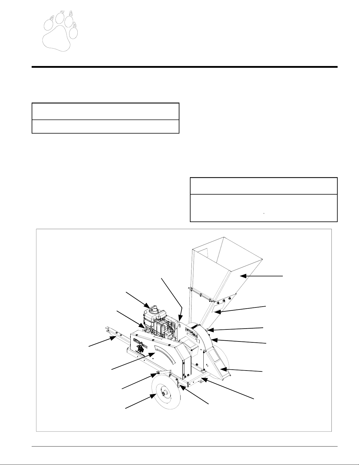
Fuel Tank
Engine
Hitch
Drive Belts and
Belt Guard
Chipper Engagement Lever
Wheels
Battery
Axle
Figure 2.1 - Chipper Assembly
Chipper Chute
Extension Chute
(S Models only)
Chipper Chute
Chipping Anvil
Disk Cover
Chipper Deflector
Trailer
Page 10
Page 8
4.5" BearCat Chipper Operator's Manual
ASSEMBLY
2.2 ASSEMBLE THE HITCH, AXLE AND WHEELS.
NOTE
REFER TO THE PARTS BOOK DURING ASSEMBLY
2.2.1 MODELS 77412, 77412S
1. When assembling the axles, the wheel base can be
adjusted from 36" to 46". Attach both axles to the hitch
pole using U-Bolts, 1/4" washers and 1/4" locknuts.
2. Slide a wheel onto the axle and secure with a 5/8" washer
and cotter pin. Repeat for the remaining wheel.
3. Position the trailer onto the axle using a hoist or jack:
3a. Standard Configuration (Figures 2.2 & 2.3): The
axle and wheels should be positioned at the end
furthest away from the engine. Secure the trailer
to the hitch pole using two 3/8" x 1" carriage bolts,
3/8" washers and 3/8" nuts. The axle mounting
brackets located on each side of the trailer are already mounted in the correct spot. Attach the axles to the axle brackets using U-bolts, 1/4" washers and 1/4" locknuts.
3b. Optional Configuration (Figure 2.4): Move the
axle mounting brackets on the side of the trailer to
the holes closest to the engine. The axle and wheels
should be positioned at the end closest to the engine. Secure the trailer to the hitch pole using two
3/8" x 1" carriage bolts, 3/8" washers and 3/8" nuts.
Attach the axles to the axle brackets using U-bolts,
1/4" washers and 1/4" locknuts.
5. Attach the hitch pole plate to the hitch pole using two
3/8" x 1" bolts, 3/8" washers and 3/8" nuts.
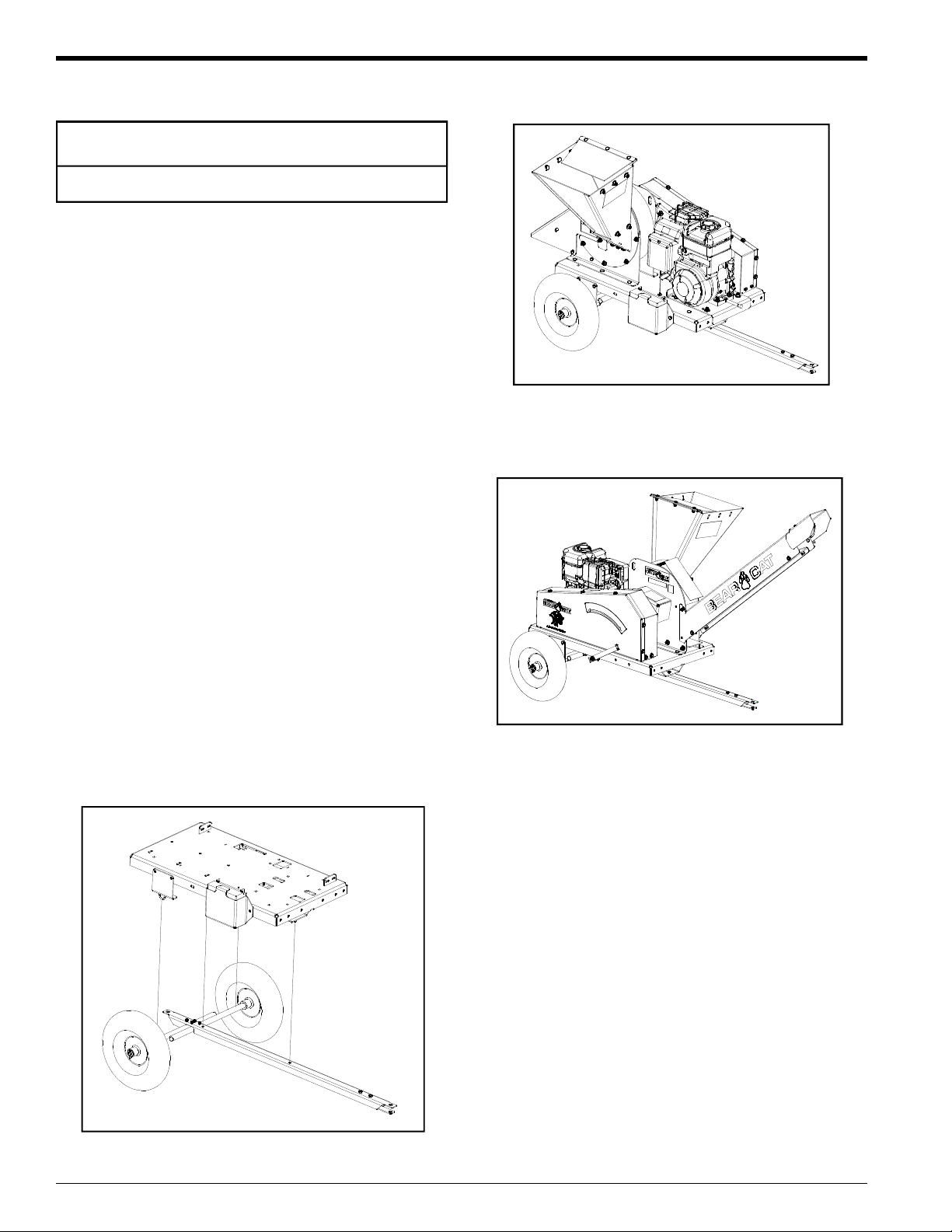
Figure 2.3 - Standard Trailer Configuration
(Models 77412, 77412S)
Figure 2.4 - Optional Trailer Configuration
(Models 77412, 77412S)
Figure 2.2 - Standard Trailer/Hitch Assembly
(Models 77412, 77412S)
Page 11

Page 9
4.5" BearCat Chipper Operator's Manual
ASSEMBLY
2.2.2 MODELS 77413, 77413S
LIGHTS
When assembling models 77413 and 77413S into the Optional Configuration, the lights on the trailer need to be moved.
Follow the steps below to move the lights:
1. Remove the bolts securing the RH light bracket and the
LH light bracket to the trailer.
2. Disconnect the trailer light wiring harness from the lights
by pushing a small screwdriver or punch into the wire
release hole (Figure 2.5).
3. Cross the lights and secure them to the other end of the
trailer. The RH light will become the LH light and the LH
light will become the RH light.
4. Connect the wiring harness.
5. Test the blinkers and brakes to ensure the lights are
properly connected.
3b. Optional Configuration (Figure 2.8): The axle
and wheels should be positioned at the end clos-
est to the engine. Locate the holes on the sides of
the trailer closest to the engine. Align these holes
to the top holes on the axle support brackets located on the axle. Secure with two 3/8" x 1" bolts,
3/8" washers and 3/8" nuts on each side.
4. Attach the fenders to the bottom holes on the axle support brackets using two bolts, washers and nuts.
HITCH ASSEMBLY
1. Attach the hitch channel to the bottom of the trailer:
1a.Standard Configuration (Figure 2.6 & 2.7): At-
tach the hitch channel on the end closest to the
engine using two 3/8" carriage bolts, 3/8" washers
and 3/8" nuts.
1b. Optional Configuration (Figure 2.8): Attach the
hitch channel on the end furthest away from the
engine using two 3/8" carriage bolts, 3/8" washers
and 3/8" nuts.
2. Attach the coupler and the coupler handle onto the hitch
pole using two 1/2" x 3-1/4" bolts, 1/2" washers and
1/2" nuts.
Figure 2.5 - Trailer Lights
AXLE AND WHEEL ASSEMBLY
1. Assemble the grease seal, bearings, hub assembly,
cotter pin and wheel cap onto one side of the axle.
Repeat for the other side.
2. Slide a wheel onto the axle and secure with four wheel
bolts. Torque the wheel bolts to 75 Ft-lb. Repeat for the
other wheel.
3. Position the trailer onto the axle using a hoist or jack:
3a. Standard Configuration (Figure 2.6 & 2.7): The
axle and wheels should be positioned at the end
furthest away from the engine. Locate the holes
on the sides of the trailer furthest from the engine.
Align these holes to the top holes on the axle support brackets located on the axle. Secure with two
3/8" x 1" bolts, 3/8" washers and 3/8" nuts on each
side.
3. Attach the safety chains, one on each side of the hitch
pole, using one 3/8" x 3-1/2" bolt, four washers (one on
each side of both safety chains) and one nut.
5. Attach the nylon lanyard to the hitch pole using one
1/4" x 3/4" bolt and 1/4" locknut. Attach a hitch pin to
the lanyard.
4. Attach the jack stand to the hitch pole using one 3/8" x
3" bolt, 3/8" washer and 3/8" nut. Use a hitch pin to
secure the jack in the raised position.
6. Insert the hitch pole into the hitch channel and attach
using one bolt, washer and nut. Secure with a hitch
pin.
Figure 2.6 - Standard Trailer/Hitch Assembly
(Models 77413, 77413S)
Page 12

Page 10
4.5" BearCat Chipper Operator's Manual
ASSEMBLY
Figure 2.7 - Standard Trailer Configuration
2.4 ATTACH THE OPTIONAL DISCHARGE TUBE
1. Move the chipper deflector weldment inside the chipper housing upward (Figure 2.11).
2. Slide the discharge tube onto the chipper housing ensuring that the weld studs fit into the notches on the
disk cover (Figure 2.10). Tighten using 5/16" flange nuts.
3. Insert two 3/8" x 5-1/2" bolt into the bolt holes on the
chipper deflector and tighten using 3/8" washers and
3/8" nylock nuts.
(Models 77413, 77413S)
Figure 2.8 - Optional Trailer Configuration
(Models 77413, 77413S)
2.3 ATTACH THE CHIPPER DEFLECTOR
1. Move the chipper deflector weldment inside the chipper
housing down towards the trailer (Figure 2.11)
2. Slide the chipper deflector onto the chipper housing ensuring that the weld studs fit into the notches on the
disk cover (Figure 2.9). Tighten using 5/16" flange nuts.
3. Insert two 3/8" x 5-1/2" bolts into the bolt holes on the
chipper deflector and tighten using 3/8" washers and
3/8" nylock nuts.
Figure 2.10 - Optional Discharge Tube
Figure 2.11 - Chipper Deflector Weldment
Figure 2.9 - Chipper Deflector
Page 13

Page 11
4.5" BearCat Chipper Operator's Manual
ASSEMBLY
2.5 ATTACH THE CHIPPER CHUTE
WARNING
Do not operate this unit without the feed chute correctly
installed. Rotating cutting blades can cause serious personal injury.
Attach the chipper chute to the chipper housing using four
3/8" x 1" bolts, 3/8" washers and locknuts (Figure 2.12).
Use two bolts on each side .
2.7 CONNECTING THE BATTERY
WARNING
To avoid sparks and a possible explosion or fire due to a
short circuit:
1. Do not touch the positive (+) battery terminal and any
surrounding metal with tools, jewelry or other metal
objects.
2. When installing battery cables, connect the positive
(+) cable first and the negative (-) cable last.
Perform the steps in this section to connect the battery:
1. Connect the positive (+) battery cable to the positive (+)
battery terminal using a 5/16 X 1” hex head bolt and 5/
16 nylock nut. An insulating boot is loosely installed on
this cable. Slide the insulating boot over the terminal
making sure that the terminal is completely covered.
2. Connect the negative (-) cable on the negative (-) battery
terminal using a 5/16 X 1” hex head bolt and 5/16 nylock
nut. There is no insulating boot for this terminal.
Figure 2.12 - Chipper Chute
2.6 ATTACH THE CHIPPER CHUTE
EXTENSION (S MODELS)
WARNING
For all S models, do not operate this unit without the
chipper chute extension correctly installed. Rotating cutting blades can cause serious personal injury.
Attach the chipper chute extension to the chipper chute
using six 3/8" x 1" carriage bolts, 3/8" washers and 3/8"
nuts (Figure 2.13). Use three bolts on each side.
Chipper Chute
Extension
IMPORTANT
DO NOT ATTEMPT TO START THE ENGINE AT THIS
TIME. Wait until you have read the complete starting
instructions in the Operation Section of this Manual.
Always use a battery that meets or exceeds the following
specifications:
Battery, Category, Lawn and Garden
BCI Group Size U1
200-250 CCA
7-3/4” X 5-3/16” X 7-5/16”
Figure 2.13 - Chipper Chute Extension
3/8" x 1" bolts and
locknuts
Chipper Chute
Page 14

Page 12
4.5" BearCat Chipper Operator's Manual
3
Controls
Section
3.1 CONTROLS
1. Engine: Refer to Engine Operator's Manual.
2. Fuel Tank: Use unleaded fuel only. DO NOT MIX OIL
AND GASOLINE.
3. Trailer Hitch: Always use a 2" ball (50mm for S Models) and hook safety chains to towing vehicle.
4. Drive Belts and Shield: Never remove shields when in
use.
5. Chipper Chute: Feed materials to be chipped through
the chute.
Battery
Fuel Tank
Engine
6. Disk Cover: Used to access the chipping disk for service and maintenance.
7. Battery: Models 77412, 77412S only.
8. Chipper Engagement Lever: Used to engage the drive
belt. Moving the lever to the chipping position engages
the drive belt. Moving the lever to the start position releases tension on the drive belt.
9. Adjustable Chipping Anvil: Check bolts for 75 Ft-lb.
torque every 8 hours.
Chipper Chute
Extension
(S models only)
Chipper Chute
Hitch
Drive Belts and
Belt Guard
Chipper Engagement Lever
Wheels
Chipping Anvil
Disk Cover
Chipper Deflector
Trailer
Axle
Figure 3.1 - Chipper Controls
Page 15

Page 13
4.5" BearCat Chipper Operator's Manual
4
Section
Operation
NOTE
Do not crank the engine continuously for more than 10
seconds at a time. If the engine does not start, allow a
60 second cool down period between starting attempts.
Failure to follow these guidelines can burn out or permanently damage, the starter motor.
NOTE
If the engine develops sufficient speed to disengage the
starter but does not keep running (false start), the engine rotation must be allowed to come to a complete
stop before attempting to restart the engine. If the starter
is engaged while the flying wheel is rotating, damage to
the starter may result.
NOTE
If the starter does not turn the engine over, shut off starter
immediately. Do not make further attempts to start the
engine until the condition is corrected. Do not jump start
using another battery. See your Briggs & Stratton engine service dealer for service assistance.
6. Move the choke to the "run" position.
For a Cold Engine - Gradually return the choke control to the "run" position after the engine starts and
warms up.
The engine/equipment may be operated during the warm
up period, but it may be necessary to leave the choke
partially on until the engine warms up.
For a Warm Engine - Return choke to the "run" position as soon as engine starts.
4.2 STARTING RECOIL MODELS
(77413, 77413S)
Move machine to clear, level area outdoors before starting.
Do not operate in the vicinity of bystanders. Make sure cutting chamber is empty before starting.
1. Check engine oil level and fill if necessary (see engine
owner's manual) before starting.
2. Turn the ignition switch clockwise to the "on" position
(if equipped).
3. Place the throttle control midway between the "slow"
and "fast" positions. Place the choke control into the
"choke" position.
4.1 STARTING ELECTRIC MODELS
(77412, 77412S)
Move machine to a clear, level area outdoors before starting. Do not operate in the vicinity of bystanders. Make sure
cutting chamber is empty before starting.
1. Check engine oil level and fill if necessary (see engine
owner's manual).
2. Place the chipper engagement lever to the start position.
3. Place the throttle control midway between the "slow"
and "fast" positions. Move the choke control to the
"choke" position.
4. Turn the key switch clockwise to the "on" position.
5. Push the starter button.
4. Pull the recoil starter until the engine starts. Make sure
the starting cord retracts.
5. Move the choke to the "run" position.
For a Cold Engine - gradually return the choke to "run"
position after the engine starts and warms up.
The engine/equipment may be operated during the warm
up period, but it may be necessary to leave the choke
partially on until the engine warms up.
For a Warm Engine - Return choke to "run" position
as soon as engine starts.
6. Move the throttle to the "fast" position
7. Slowly engage the chipper engagement lever to the chipping position.
Page 16

Page 14
4.5" BearCat Chipper Operator's Manual
OPERATION
4.3 STOPPING ELECTRIC MODELS
(77412, 77412S)
WARNING
Allow the chipper to come to a complete stop before inspection and servicing. The rotor is heavy and has inertia
built up that will allow the rotor to continue to turn for
some time after the chipper has been disengaged. You
can tell when the rotor has come to a complete stop
when there is no noise or machine vibration present. You
can reengage the chipper engagement lever to slow the
rotor to a stop.
1. Move the throttle to the "slow" position.
2. Move the chipper engagement lever to the "start" position.
3. Allow the engine to run at idle for 30-60 seconds.
4. Stop the engine by moving the throttle to the "stop"
position or turning off the ignition key.
5. Allow machine to come to a complete stop.
4.5 CHIPPING
The Bear Cat chipper is designed to chip a variety of materials into a more readily decomposable condition. The following guidelines can be useful in getting you started.
WARNING
Keep face and body away from the feed opening. Do not
overreach. Keep proper balance and footing at all times.
1. Run unit at full operating speed before starting to chip
material.
2. Select limbs that are up to 4-1/2" inches in diameter.
Trim side branches off that cannot be bent enough to
feed into the chipper chute. Hold small diameter branches
together in a bundle and feed in simultaneously.
3. Feed brush from the side of the chipper chute, rather
than from the front. Then step aside to avoid being hit
by the brush moving into the chipper.
4. Do not lean over the chipper chute to push objects into
the cutting device. Use a push stick or brush paddle.
4.4 STOPPING RECOIL MODELS
(77413, 77413S)
WARNING
Allow the chipper to come to a complete stop before inspection and servicing. The rotor is heavy and has inertia
built up that will allow the rotor to continue to turn for
some time after the chipper has been disengaged. You
can tell when the rotor has come to a complete stop
when there is no noise or machine vibration present. You
can reengage the chipper engagement lever to slow the
rotor to a stop.
1. Move the throttle to the "slow" position.
2. Move the chipper engagement lever to the "start" position.
3. Allow the engine to run at idle for 30-60 seconds.
4. Stop the engine by turning off the ignition switch counterclockwise.
5. Allow machine to come to a complete stop.
5. Never use shovels or forks to push brush. They can be
chipped, are expensive to replace, and can cause extensive damage to the chipper. In addition, metal pieces
can fly out and cause serious injury.
6. Never push brush into the chipper chute with your feet.
7. Place limb, butt end first, into the chipper chute until it
contacts the chipping blades. The actual feed rate of
the limb into the chipper will depend on the type of material being fed and sharpness of the cutting blades.
8. The operator needs to control the rate of feed into the
chipper. Do not place material into the chipper chute
and walk away. This could result in serious injury or
damage to the machine.
9. If the engine slows to where it may stall, stop feeding
the material and allow the engine to recover.
10. If the chipper jams, refer to Section 5.7.
11. Alternately insert and retract the limb or insert continuously at a rate that will not kill the engine. Rotating the
branch as it is being fed will improve cutting action.
12. Chipping dead, dry material will create heat and dull the
chipping blades quickly.
13. Alternate greener material with dry material to lubricate
the chipping blades for longer life and better performance.
14. When the chipping blades become dull, they will require sharpening (Section 5).
Page 17

Page 15
4.5" BearCat Chipper Operator's Manual
4.6 HOOKING & UNHOOKING CHIPPER (MODEL 77413, 77413S)
The machine is closely balanced. Do not lift higher than
necessary to prevent tipping over of machine. Refer to Figure
4.1 when hooking and unhooking the chipper.
HOOKING:
1. Open the coupler latch.
2. Raise the trailer hitch until the coupler is above the height
of the hitch ball on the towing vehicle.
3. Lower the trailer hitch until the coupler fully engages
the hitch ball.
4. Close the coupler latch securing the coupler to the hitch
ball.
5. Install the hitch pin through the coupler latch.
6. Cross the safety chains under the hitch and connect to
towing vehicle.
OPERATION
7. Raise the jack stand and secure to the hitch using a
hitch pin.
UNHOOKING:
1. Unhook the safety chains from the towing vehicle. Latch
safety chains to the hitch to prevent them from interfering with chipping.
2. Remove the hitch pin from the coupler latch.
3. Unlatch the coupler and disconnect the hitch coupler
from the hitch ball.
4. Move the hitch of the chipper away from the hitch ball.
5. For models 77413 and 77413S, lower the jack stand
and secure with a hitch pin.
Figure 4.1 - Trailer Hitch Controls (Model 77413, 77413S)
Page 18

Page 16
4.5" BearCat Chipper Operator's Manual
5
Section
Service and Maintenance
5.2 SHARPENING CHIPPER BLADES
WARNING
Before inspecting or servicing any part of the machine,
shut off the power source, disconnect the spark plug wire
from the spark plug and make sure all moving parts have
come to a complete stop. The chipping blades are sharp!
Use care when working on the machine to avoid injury.
5.1 INSTALLING THE DISK LOCK
When working on the disk assembly, use the lock
mechanism at all times (Figure 5.1). Follow the steps below
to install the rotor lock:
1. Remove the chipper deflector.
2. Rotate the chipper disk until the hole on the chipper
paddle is aligned with the hole on the chipper housing
(Figure 5.1).
3. Install a punch or screwdriver into the holes.
NOTE
One of the 3/8" x 5-1/2" bolts from removing the chipper
deflector can also be used to lock the disk.
WARNING
The chipping blades are sharp! Use care when working
on the machine to avoid injury.
NOTE
The chipper blades consist of two edges (Figure 5.2).
When the first edge dulls, flip the blade and torque to 75
Ft-lb to use the second sharp edge. After both edges are
dull, sharpen the chipper blades.
When the chipper blades dull, chipping becomes difficult. It
is recommended that the chipper blades are sharpened every 5-15 hours of chipper operation. Follow the steps below
to sharpen the chipping blades.
1. To remove the chipper deflector from the chipper housing, remove the two 3/8" x 5-1/2 bolts securing the deflector to the chipper housing and loosen the 5/6" flange
nuts on the weldment bolts. Remove the deflector.
2. Install the disk lock (Section 5.1). The disk is now restrained for removing the blades. To access the remain-
ing blades, remove the punch or screwdriver, reposition
the disk and return the punch or screwdriver to the disk
lock hole.
Disk Lock Hole
Figure 5.1 - Disk Lock
Chipper Disk
Matching hole on
Disk Paddle
3. Remove the two 1/2" x 1-3/4" flat head screws holding
the blade to the disk.
4. When sharpening the blades, be sure to maintain the
original 45 degree angle. Be careful when grinding so
the blade material does not get too hot and change
color. This will remove the blade's special heat treated
properties. Use short grinding times and cool with water. Remove an equal amount off each blade to maintain
balance.
5. Reinstall blade and torque to 75 Ft-lb. Repeat this procedure for each blade.
Figure 5.2 - Chipper Blade Surfaces
Page 19

Page 17
4.5" BearCat Chipper Operator's Manual
SERVICE AND MAINTENANCE
5.3 REPLACING CHIPPING BLADES
If the chipper blade does not extend beyond the disk chipping slot, follow the steps below to replace the chipping
blade:
1. Remove the chipper deflector or discharge tube.
2. Lock rotor assembly (Section 5.1).
3. Remove the two 1/2" x 1-3/4" flat head screws holding
the blade to the disk.
4. Remove the old blade, install the new blade and torque
to 75 Ft-lb. Repeat this procedure for each blade.
5.4 SETTING CHIPPING BLADE
CLEARANCE
The chipping blades should clear the chipping anvil located
directly under the chipper chute by 1/16 inch. To adjust the
blade clearance, proceed as follows:
1. Removing the chipper chute is NOT required for setting
the chipping blade clearance, although, removing the
chipper chute can provide better access for measuring
the chipping blade clearance.
2. Rotate the disk until a chipping blade is even with the
chipping anvil.
3. Measure the amount of clearance between the chipping blade and chipper anvil from inside of the chipper
housing. The gap should be 1/16 inch (Figure 5.3).
4. Adjust the anvil by loosening the 5/16" x 5/8" bolts
holding the anvil to the disk cover and sliding the anvil
inward or outward until the desired measurement is
achieved.
5. Tighten the bolts and torque to 75 Ft-lbs.
6. IMPORTANT: Repeat for the remaining chipping blades.
7. Reinstall the chipper chute.
If the chipping anvil edge is damaged or worn unevenly,
remove the three bolts and washers holding the anvil to the
disk cover and use one of the other three edges. Adjust for
correct measurement.
5.5 ADJUSTING THE DRIVE BELT
Check the condition of the drive belt annually or after every
25 hours of operation, whichever comes first. Replace a
cracked, frayed, worn or stretched drive belt. Only replace
drive belt with original banded type belt. Do not use single
type belts. To adjust the drive belt, proceed as follows:
1. Move the chipper engagement lever to the start position.
2. Shut engine off.
3. Disconnect battery cables.
4. Remove the belt shield by removing the seven 5/16" x
3/4" bolts securing the belt shield to the shield weldment.
5. Loosen the 5/16" bolt attaching the belt guide to the
engine.
6. To increase tension on the belt, do the following:
6a. Loosen the four carriage bolts attaching the
engine plate to the trailer.
6b. Locate the two 5/16" x 2" bolts and 5/16" flange
nuts located on the side of the chipper between
the trailer and the engine plate.
6c. Loosen both 5/16" flange nuts.
6d. Tighten both 5/16" bolts equally to move the
engine away from the chipper housing until the
belt deflection is 7/16" when a 20 lb. load is
placed against the belt (Figure 5.4).
6e. Tighten the four carriage bolts securing the en-
gine plate to the trailer.
6f. Once the proper deflection is achieved, tighten
both 5/16" flange nuts to ensure the proper de-
flection is maintained.
7. If the bolts and nuts between the engine plate and the
trailer cannot be adjusted any further and the tension
needs further adjustment, tighten the eyebolt until the
appropriate deflection is achieved.
8. Replace the belt if no adjustment is left (Section 5.6).
9. Replace belt shield.
Chipper
Blade
Anvil
Chipper Disk
1/16"
Figure 5.4 - Belt TensionFigure 5.3 - Chipper Blade and Anvil Clearance
Page 20

Page 18
4.5" BearCat Chipper Operator's Manual
SERVICE AND MAINTENANCE
5.6 REPLACING DRIVE BELTS
Check the condition of the drive belt annually or after every
25 hours of operation, whichever comes first. Replace a drive
belt that is cracked, frayed, worn, or stretched. Only replace the drive belt with original banded type belts, do not
use single type belts. To adjust the drive belt, proceed as
follows:
1. Move the chipper engagement lever to the start position.
2. Shut engine off.
3. Disconnect battery cables.
4. Remove the belt guard. Two 5/16" x 1" bolts are located
on each side of the belt guard.
5. Remove the idler pulley.
6. Move the chipper engagement lever to the chipping position.
7. Loosen the two 3/8" x 4-1/2" bolts located in the middle
of the belt guide.
8. Remove the 5/16" bolt attaching the belt guide to the
engine.
5.7 CLEARING A PLUGGED DISK
WARNING
To prevent personal injury or property damage: Shut off
engine, disconnect spark plug wire, remove ignition key,
and make sure that all moving parts have come to a complete stop before servicing, adjusting or repairing.
1. Stop engine, disengage disk by moving the chipper engagement lever to the start position, and allow machine
to come to a complete stop. Remove the spark plug wire.
2. Remove the chipper deflector and/or disk cover. Remove
debris, taking care to avoid the chipper blades which can
be extremely sharp.
3. Once debris is removed, replace the chipper deflector
and/or disk cover.
4. Replace spark plug wire, restart engine and resume operation.
9. Loosen the bolt attaching the belt guide to the front
rotor bearing. The belt guide should be able to slide up
and down in the slot on the belt guide.
10. Loosen the four carriage bolts attaching the engine plate
to the trailer.
11. Locate the two 5/16" x 2" bolts and 5/16" nuts located
on the side of the chipper between the trailer and the
engine plate.
12. Loosen both 5/16" flange nuts.
13. To release the tension on the belt, loosen both 5/16" x
2" bolts equally and slide the engine towards the chipper housing.
14. Lift the belt guide away from the belt; remove the old
belt and install the new belt.
15. Adjust the drive belt (Section 5.5).
16. Lower the belt guide and reinstall. The bolt attaching
the belt guide to the front rotor bearing must be torqued
to 75 Ft-lb.
17. Move the chipper engagement lever to the start position
and reinstall the idler pulley.
WARNING
Never try to run the unit without the chipper housing cover
and/or chipper deflector in place.
18. Reinstall the belt guard.
Page 21

Page 19
4.5" BearCat Chipper Operator's Manual
SERVICE AND MAINTENANCE
5.8 REPLACING ROTOR BEARINGS.
WARNING
The rotor assembly has a lock mechanism (Section 5.1).
When working on the rotor assembly, use the lock mechanism at all times.
REMOVING THE OLD BEARINGS
1. Move the chipper engagement lever to the start posi-
tion.
2. Shut engine off.
3. Disconnect battery cables.
4. Remove the belt guard. Two 5/16" x 1" bolts are located
on each side of the belt guard.
5. Remove the idler pulley.
6. Move the chipper engagement lever to the chipping po-
sition.
7. For models 77412 and 77412S, the belt guard will have
to be removed. To do this, remove the 1/2" bolt attaching the belt guide to the rotor bearing and the 5/16" bolt
attaching the belt guide to the engine.
8. Remove the belt.
9. To remove the rotor sheave, do the following:
11b. Loosen the setscrews securing the back bearing
to the rotor shaft.
11c. Remove the two 1/2" x 1-1/2" bolts and 1/2"
centerlock nuts holding the back bearing to the
chipper housing.
11d. Slide the chipper disk out from the chipper hous-
ing until the bearing slides off the rotor shaft.
WARNING
The chipping blades are sharp! Use care when working
on the machine to avoid injury.
INSTALLING THE NEW BEARINGS
1. Slide the chipper disk into the chipper housing.
2. As the rotor shaft slides through the hole in the chipper
housing, slide the new back bearing onto the rotor shaft.
WARNING
It is extremely important to slide the rotor assembly forward to remove any existing play in the rotor assembly.
Failure to do so could result in the chipper blades striking the chipping anvil which could result in serious injury
or death.
9a. Remove the three bolts securing the rotor sheave to
the rotor shaft.
9b. Reinstall the bolts into the second set of holes. As
the bolts are tightened, the sheave will be pushed
off the rotor shaft.
10. To remove the front bearing, do the following:
10a. Remove the snap ring.
10b. Loosen the setscrews securing the front bearing
to the rotor shaft.
10c. Remove the two 1/2" x 1-1/2" bolts and 1/2"
centerlock nuts holding the front bearing to the
chipper housing.
10d. Slide the front bearing off the rotor shaft.
10e. Remove the second snap ring.
11. To remove the back bearing do the following:
11a. Remove the seven 5/16" nylock nuts and wash-
ers securing the disk cover to the chipper housing.
3. Tighten the two 1/2" x 1-1/2" bolts and 1/2" centerlock
nuts securing the back bearing to the chipper housing.
Torque to 75 Ft-lb.
4. Slide a snap ring, front bearing and another snap ring
onto the rotor shaft.
5. Tighten the two setscrews securing the front bearing to
the rotor shaft.
6. Tighten the two setscrews located on both the front and
back bearings securing the bearings to the rotor shaft.
7. Replace the rotor sheave and tighten the three bolts
into the correct holes to secure the sheave to the rotor
shaft.
8. Ensure the chipper engagement lever is in the chipping
position
9. Replace the belt. Using a straight edge, check the belt
alignment. The rotor sheave and the engine sheave must
be flush.
10. For models 77412 and 77412S, reinstall the belt guide.
11. Move the chipper engagement lever to the start position
and reinstall the idler pulley.
12. Replace the belt guard and resume operation.
Page 22

Page 20
4.5" BearCat Chipper Operator's Manual
SERVICE AND MAINTENANCE
5.9 GREASEABLE BEARINGS
NOTE
Polyuria and lithium based greases are not compatible.
Mixing the two grease types may lead to premature failure of the chipper.
NOTE
The use of pneumatic grease equipment is not recommended unless low pressure is assured.
Mounted bearings are pre-lubricated at our factory and
are ready for operation.
RELUBRICATION:
Relubrication of bearings is determined by operating conditions and environment. Lubricate standard bearings with a
LITHIUM based grease. Greasing intervals and quantities
are shown on the next page using the following symbol:
Frequency (i.e. 50 hours).
Quantity
Recommended
quantity of grease.
GREASING INTERVALS:
Bearings in extreme environments will require more frequent
greasing intervals.
GREASE FILL AMOUNTS:
It is preferred that experience dictate fill amounts due to
wide variances in applications, greasing equipment and operating conditions. The quantities shown on the next page
are recommended amounts. In most cases, it is best to
lubricate in small amounts, under low pressure, until a thin
bead of fresh grease is visible at the seal lip area.
Care should be taken when greasing bearings to avoid overfilling. Overfilling can lead to excessive heat and/or unseating of the seals. Grease should be introduced in small
amounts and under light pressure. Whenever possible, the
bearing should be rotated slowly while grease is added to
ensure equal distribution throughout the raceways.
The chipper models described in this manual have several
greaseable bearings that require greasing. Refer to the Figures 5.5 through 5.8 on the next page for greasing locations, intervals and quantities.
Page 23

Page 21
4.5" BearCat Chipper Operator's Manual
5.9 GREASABLE BEARINGS (CON'T)
SERVICE AND MAINTENANCE
.18oz
5 GRAMS
Figure 5.5 - Engagement
Lever (All Models)
.10 oz
(3 GRAMS)
Figure 5.8 - Front and Back
Rotor Bearings (All Models)
.10 oz
(3 GRAMS)
Figure 5.6 - Wheel Bearing
(Models 77413, 77413S)
.07 oz
(2 GRAMS)
Figure 5.7 - Wheel Bearing
(Models 77412, 77412S)
Page 24

Page 22
4.5" BearCat Chipper Operator's Manual
SERVICE AND MAINTENANCE
5.10 OTHER SERVICE AND MAINTENANCE TIPS
1. Service engine according to engine owners manual.
Change oil and filter as recommended in manual.
2. Check all bolts and other fasteners for correct torque
(Section 7.2) after every 8 hours of operation.
5.11 TRAILER SERVICE TIPS
1. Check wheel bolt torque every 8 hours of towing use.
2. Check air pressure in tires every 8 hours of towing.
3. Check and repack wheel bearings with grease every 12
months.
4. Connect safety chains when towing.
5. Tighten and secure trailer hitch bolts.
6. Check trailer lights.
Page 25

Page 23
4.5" BearCat Chipper Operator's Manual
6
Clear rotor, feed material into shredder
Rotate branch or material when feeding
Troubleshooting
Section
6.1 GENERAL TROUBLESHOOTING
Problem Possible Cause Correction
Improper control settings Use proper setting
Lack of fuel Fill fuel tank
Engine will not start
Engine or rotor stalls or stops
Hard to feed chipper requires
excessive power
Internal problems See dealer
Spark plug disconnected Connect spark plug
Dirty, stale, or contaminated gas Refill tank with fresh gasoline
Obstructed discharge
Improper blade clearance Adjust clearance
Dull chipper blades Sharpen blades
Feeding material too fast into chipper Slow feed rate
Plugged rotor Clear rotor
Dull chipper blades Sharpen blades
Improper blade clearance Adjust clearance
Obstructed discharge
Use branch or similar object to clear
discharge
Use branch or similar object to clear
discharge
Engine stalls or belt squeals
when engaging chipper
Material from chipper wraps
around the rotor shaft
Engaging chipper too fast Engage lever more slowly
Plugged rotor
Belt tension too loose Tighten or replace belt
Stringy, green material bypasses
chipper blades
Improper blade clearance Adjust clearance
Chipper blades to anvil clearance is
incorrect
Dull chipper blades Sharpen or replace blades
Set chipper blade to anvil clearance to
recommended distance (1/16" to 1/8")
more evenly
to cut completely
Page 26

Page 24
4.5" BearCat Chipper Operator's Manual
TROUBLESHOOTING
Check rotor to see if rotor is assembled
Contact authorized dealer to order Bear
6.1 GENERAL TROUBLESHOOTING (CONTINUED)
Problem Possible Cause Correction
Drive system vibration
Excessive vibration while
running
Rotor out of balance
Check drive belts and pulleys for bad
or worn areas. Check PTO shaft for
wear.
Inspect rotor for broken or missing
chipper blades. Repair if needed.
correctly.
Rotor will not turn
Cannot engage chipper
Chipper blade to anvil clearance is
incorrect
Drive belt too loose or broken Adjust or replace
Obstructed discharge
Plugged rotor Clear rotor (Section 5.7)
Improper belt installation Install belt properly
Shock absorber binding Replace shock absorber
Improper belt tension Tighten or loosen belt as needed
Engagement spring binding in spring
cover
Pulleys not aligned Aligned pulleys with straight edge
Clutch pedal binding Determine cause and repair
Set chipper blade to anvil clearance to
recommended distance (1/16" to 1/8")
Use branch or similar object to clear
discharge
Remove spring cover and clean
Excessive belt wear
Trailer sways during towing Tire air pressure not correct Check tire sidewall for inflation limits
Plugged discharge tube
Not using correct belt
Pulley damaged or wore Replace pulley
Pulley not in alignment Align pulley with straight edge
Belt tension too loose Tighten belt or replace
Engine speed too slow Increase engine speed
Feeding material too fast into chipper Slow feed rate
Cat belts
Page 27

Page 25
4.5" BearCat Chipper Operator's Manual
7
(45 lbs. w/out blades)
(45 lbs. w/out blades)
Specifications
Section
7.1 SIZE SPECIFICATIONS
Specifications are subject to change due to design modifications.
Specifications (77412, 77412S)
Overall Size
Max. Chipper Capacity (Dia.) 4-1/2"
Chipper Blade Qty.
Rotor Size 14" Dia. X 1"
Rotor Weight (w/blades)
Discharge Size
Drive Type Belt
Belt Size 2RB61 Armid Construction
Weight (lbs.)
Wheel Base Adjustable 35" to 46"
Tires 480/400 x 8 Pneumatic
Fuel Tank Capacity (gal.) 4 qts. w/shutoff valve
Engine
68" x 43" x 41-1/2" (77412)
68" x 57" x 53" (77412S)
2 reversible
(3/8" x 5-3/32" x 4")
49 lbs.
4.5" x 9" (standard)
4.5" x 4.5" (optional)
400 lbs. (77412)
448 lbs. (77412S)
12 HP B&S Electric Start Intek
(gasoline)
Specifications (77413, 77413S)
Overall Size
Max. Chipper Capacity (Dia.) 4-1/2"
Chipper Blade Qty.
Rotor Size 14" Dia. X 1"
Rotor Weight (w/blades)
Discharge Size
Drive Type Belt
Belt Size 2RB61 Armid Construction
Weight (lbs.)
Wheel Base 44"
Tires 4.80-8 Load Rating B
Fuel Tank Capacity (gal.) 1.72 gallons
Engine
76" x 43.5" x 46" (77413)
76" x 57.5" x 58" (77413S)
2 reversible
(3/8" x 5-3/32" x 4")
49 lbs.
4.5" x 9" (standard)
4.5" x 4.5" (optional)
450 lbs. (77413)
498 lbs. (77413S)
Honda OHV 13 HP
(gasoline)
Page 28

Page 26
4.5" BearCat Chipper Operator's Manual
SPECIFICATIONS
7.2 BOLT TORQUE
CHECKING BOLT TORQUE:
The tables shown below give correct torque values for various bolts and capscrews. Tighten all bolts to the torques specified
in chart unless otherwise noted. Replace hardware with the same strength bolt.
SAE - 8SAE - 2ASAE - 5
ENGLISH TORQUE
Bolt
Diameter
1/4" 7.5 5.5 9.5 9 17 12.5
5/16" 15 11 25 18 35 26
3/8" 27 20 44 33 63 46
7/16" 44 32 70 52 100 75
1/2" 67 50 110 80 150 115
9/16" 95 70 155 115 225 160
5/8" 135 100 215 160 300 225
3/4" 240 175 375 280 550 400
7/8" 240 175 625 450 875 650
1" 360 270 925 675 1300 975
1-1/8" 510 375 1150 850 1850 1350
1-1/4" 725 530 1650 1200 2600 1950
SAE 2 SAE 5 SAE 8
A
Bolt Torque*
METRIC TORQUE SPECIFICATIONS
Bolt
Diameter
M3 0.5 0.4 - - - - - M4 3 2.2 - - - - - M5 5 4 - - - - - M6 6 4.5 11 8.5 17 12 19 14.5
M8 15 11 28 20 40 30 47 35
M10 29 21 55 40 80 60 95 70
M12 50 37 95 70 140 105 165 120
M14 80 60 150 110 225 165 260 190
M16 125 92 240 175 350 255 400 300
M18 175 125 330 250 475 350 560 410
M20 240 180 475 350 675 500 800 580
M22 330 250 650 475 925 675 1075 800
M24 425 310 825 600 1150 850 1350 1000
M27 625 450 1200 875 1700 1250 2000 1500
4.8 8.8 10.9 12.9
Bolt Torque*
Torque figures indicated above are valid for non-greased or non-oiled threads and heads unless otherwise specified. Therefore, do not grease or
oil bolts or capscrews unless otherwise specified in this manual. When using locking elements, increase torque values by 5%.
* Torque value for bolts and capscrews are identified by their head markings.
Page 29

Declaration of Conformity
The undersigned manufacturer:
Crary Industries, Inc.
237 NW 12
P.O. Box 849
West Fargo, ND 58078-0849
Declares that hereunder specified unit:
CHIPPER
Brand: Crary Bear Cat
Type: Engine driven Chipper
Model Number: 77412S
Complies with the requirements of:
Machinery Directive 2006/42/EC
EN 13525:2005-Forestry Machinery-Wood Chippers -Safety
Emission of Gaseous and Particulate Pollutants Directive 2002/88/EC
EN ISO 12,100, Part 1-Safety of Machinery-Basic Conce pt s, General Principles for Design
Noise Emissions Directive 2000/14/EC
-Conformity Assessment Procedure: Annex V
(Use of harmonized standard EN ISO 3744:2010)
Sound Power Level: 87 dB L
Guaranteed Sound Power Level: 107 dB LWA
77412S Serial number 403349 and up
West Fargo, ND 58078-0849
June 29, 2011
CRARY INDUSTRIES, INC. The authorized representative in Europe who is authorized to
compile the technical file:
Company: Atlantic Bridge Limited
Address: Atlantic House, PO Box 4800
Earley, Reading RG5 4GB, United Kingdom
______________________________
Arlan Mathias Mr. Phillip Wicks
Senior Project Engineer
PA
th
Street
Data contained in this document pertains only to machines sold in areas that require CE compliance
standards. To identify if your machine is CE compliant, it will have the following CE mark decal:
Page 30

Declaration of Conformity
The undersigned manufacturer:
Crary Industries, Inc.
237 NW 12
P.O. Box 849
West Fargo, ND 58078-0849
Declares that hereunder specified unit:
CHIPPER
Brand: Crary Bear Cat
Type: Engine driven Chipper
Model Number: 77413S
Complies with the requirements of:
Machinery Directive 2006/42/EC
EN 13525:2005-Forestry Machinery-Wood Chippers -Safety
Emission of Gaseous and Particulate Pollutants Directive 2002/88/EC
EN ISO 12,100, Part 1-Safety of Machinery-Basic Conce pt s, General Principles for Design
Noise Emissions Directive 2000/14/EC
-Conformity Assessment Procedure: Annex V
(Use of harmonized standard EN ISO 3744:2010)
Sound Power Level: 87 dB L
Guaranteed Sound Power Level: 102 dB LWA
77413S Serial numbers 407998 and up
77413S VIN numbers 5VJAA00137W000443 and up
West Fargo, ND 58078-0849
June 29, 2011
CRARY INDUSTRIES, INC. The authorized representative in Europe who is authorized to
compile the technical file:
Company: Atlantic Bridge Limited
Address: Atlantic House, PO Box 4800
Earley, Reading RG5 4GB, United Kingdom
______________________________
Arlan Mathias Mr. Phillip Wicks
Senior Project Engineer
PA
th
Street
Data contained in this document pertains only to machines sold in areas that require CE compliance
standards. To identify if your machine is CE compliant, it will have the following CE mark decal:
Page 31

Crary Company
237 12th St. NW • P.O. Box 849
West Fargo, ND 58078-0849
(701)282-5520 • FAX: (701)282-9522
www.crary.com
www.lockwoodmfg.com
Manufactured in the
United States of America
by Crary Company
 Loading...