

Page 1

4.5 InCH
mADE WITH pRIDE IN THE...
CHIppers
77412 - 342CC BRIGGS ELECTRIC
START
77413 - 390CC HONDA TOWABLE
77454 - 540 pTO
77412S - 342CC BRIGGS ELECTRIC
START
f - mANuEL Du pROpIÉTAIRE
77413S - 390CC HONDA TOWABLE
77454S - 540 pTO
en - OWNER'S mANuAL
pN: 14783-00 R060107
Companion to 14784-00
owner's manual
eS - mANuAL DEL pROpIETARIO
Page 2

Before You Begin
DEAR ECHO BEAR CAT CUSTOMER
Thank you for purchasing a ECHO Bear Cat product. The ECHO Bear Cat line is designed, tested, and manufactured
to give years of dependable performance. To keep your machine operating at peak efciency, it is necessary to adjust
it correctly and make regular inspections. The following pages will assist you in the operation and maintenance of your
machine. Please read and understand this manual before operating your machine.
If you have any questions or comments about this manual, please call us toll-free at 1-800-247-7335.
If you have any questions or problems with your machine, please call or write your local authorized ECHO Bear Cat Dealer.
This document is based on information available at the time of its publication. ECHO Bear Cat is continually making
improvements and developing new equipment. In doing so, we reserve the right to make changes or add improvements
to our product without obligation for equipment previously sold.
PLEASE SEND US YOUR WARRANTY CARD
A warranty card is included in your owner's kit packaged with your machine. Please take the time to ll in the information
requested on the card. When you send your completed card to us, we will register your machine and start your
coverage under our limited warranty.
PARTS ORDERING INFORMATION
For service assistance, contact your authorized ECHO
Bear Cat dealer or the factory. For parts, contact your
authorized ECHO Bear Cat dealer. Your dealer will need to
know the serial number or VIN of your machine to provide
the most efcient service. See below for information on
how to identify and record the identication number for
your machine.
If you need engine service or parts:
For engine service or parts, contact your local authorized
engine dealer. An authorized engine dealer can handle
all parts, repairs, and warranty service for the engine.
IDENTIFICATION NUMBER LOCATION
Your machine will have either a serial number or vehicle
identication number (VIN). VINs are located on the left
side of the trailer frame near the hitch. They are 17-digit
numbers of the format: 5VJAA001XXWXXXXX. Serial
numbers are located on the machine body. They are 6digit numbers.
Record your identication number in the space provided
and on the warranty registration card.
REPLACEMENT PARTS
Only genuine ECHO Bear Cat replacement parts should
be used to repair the machine. Replacement parts
manufactured by others could present safety hazards,
even though they may t on this machine. Replacement
parts are available from your ECHO Bear Cat dealer.
Provide the following when ordering parts:
The SERIAL NUMBER OR VIN of your machine.
The PART NUMBER of the part.
The PART DESCRIPTION.
The QUANTITY needed.
SERIAL NUMBER OR VIN
HOW TO CON TAC T E C HO BE AR CAT
ADDRESS PHONE E-MAIL HOURS
237 NW 12th Street
P.O. Box 849
West Fargo, ND 58078
© 2006, CRARY INDUSTRIES, ALL RIGHTS RESERVED. PRODUCED AND PRINTED IN THE U.S.A.
800-247-7335
701-282-5520
FAX: 701-282-9522
opesales@crary.com
service@crary.com
Monday - Friday,
8 am to 5 pm
Central Time
Page 3

limiTed WarranTY
This warranty applies to all AG and Outdoor power Equipment manufactured by Crary Industries.
Crary Industries warrants to the original owner each new Crary Industries product to be free from defects
in material and workmanship, under normal use and service. The warranty shall extend 1 year from date of
delivery for income producing (commercial) applications and 2 years from date of delivery for non-income
producing (consumer) use of the product. The product is warranted to the original owner as evidenced by a
completed warranty registration on file at Crary Industries. Replacement parts are warranted for (90) days
from date of installation.
The WarranTY regiSTraTion muST be comPleTed and reTurned To crarY induSTrieS
WiThin 10 daYS of deliverY of The ProducT To The original oWner or The WarranTY
Will be void.
In the event of a failure, return the product, at your cost, along with proof of purchase to the selling Crary
Industries dealer. Crary Industries will, at its option, repair or replace any parts found to be defective in material
or workmanship. Warranty on any repairs will not extend beyond the product warranty. Repair or attempted
repair by anyone other than a Crary Industries dealer as well as subsequent failure or damage that may occur
as a result of that work will not be paid under this warranty. Crary Industries does not warrant replacement
components not manufactured or sold by Crary Industries.
This warranty applies only to parts or components that are defective in material or workmanship.
1.
This warranty does not cover normal wear items including but not limited to bearings, belts, pulleys, filters
2.
and chipper knives.
This warranty does not cover normal maintenance, service or adjustments.
3.
This warranty does not cover depreciation or damage due to misuse, negligence, accident or improper
4.
maintenance.
This warranty does not cover damage due to improper setup, installation or adjustment.
5.
This warranty does not cover damage due to unauthorized modifications of the product.
6.
Engines are warranted by the respective engine manufacturer and are not covered by this warranty.
7.
Crary Industries is not liable for any property damage, personal injury or death resulting from the unauthorized
modification or alteration of a Crary product or from the owner’s failure to assemble, install, maintain or operate
the product in accordance with the provisions of the Owner’s manual.
Crary Industries is not liable for indirect, incidental or consequential damages or injuries including but not
limited to loss of crops, loss of profits, rental of substitute equipment or other commercial loss.
This warranty gives you specific legal rights. you may have other rights that may vary from area to area.
Crary Industries makes no warranties, representations or promises, expressed or implied as to the performance
of its products other than those set forth in this warranty. Neither the dealer nor any other person has any
authority to make any representations, warranties or promises on behalf of Crary Industries or to modify the
terms or limitations of this warranty in any way. Crary Industries, at its discretion, may periodically offer limited,
written enhancements to this warranty.
crarY induSTrieS reServeS The righT To change The deSign and/or SPecificaTionS
of iTS ProducTS aT anY Time WiThouT obligaTion To PreviouS PurchaSerS of iTS
ProducTS.
4.5 INCH CHIPPER
1
Page 4

Table of conTenTS
deScriPTion Page deScriPTion Page
SafeTY .................................................................3
1.1 SAFETy ALERT SymBOL ......................................... 3
1.2 EmISSION INFORmATION ........................................3
1.3 BEFORE OpERATING .............................................. 4
1.4 OpERATION SAFETy ...............................................4
1.5 pTO SAFETy .............................................................5
1.6 BATTERy SAFETy .................................................... 5
1.7 mAINTENANCE/STORAGE SAFETy .......................6
1.8 TOWING SAFETy .....................................................6
1.9 SAFETy DECALS ......................................................7
1.10 SAFETy DECAL LOCATIONS ................................... 8
1.10.1 mODELS 77412, 77412S..............................8
1.10.2 mODELS 77413, 77413S..............................9
1.10.3 mODELS 77454, 77454S............................10
aSSemblY ..........................................................11
2.1 TRAILER ASSEmBLy (342CC mODELS) ................11
2.2 TRAILER ASSEmBLy (390CC mODELS) ............... 12
2.2.1 LIGHTS ......................................................... 12
2.2.2 AxLE AND WHEEL ASSEmBLy ...................12
2.2.3 HITCH ASSEmBLy .......................................13
2.3 DISCHARGE ASSEmBLy ........................................13
2.3.1 DISCHARGE CAp ........................................13
2.3.2 DISCHARGE TuBE (OpTIONAL) .................13
2.4 CHuTE ASSEmBLy .................................................14
2.5 CHuTE ExTENSION ............................................... 14
2.5.1 ExTENSION TRAy (77412S, 77413S) ......... 14
2.5.2 CHuTE ExTENSION (77454S) .................... 15
2.6 BATTERy INSTALLATION (342CC mODELS) ........ 15
2.7 CHECkING FLuIDS (ENGINE mODELS) ............... 15
2.7.1 CHECkING/ADDING mOTOR OIL ...............15
2.7.2 FILLING THE FuEL TANk ............................ 16
2.8 DRIvELINE CONNECTION (pTO mODELS) .......... 16
Service & mainTenance ...............................23
4.1 mAINTENANCE SCHEDuLE .................................. 23
4.2 INSTALLING THE DISk LOCk ................................23
4.3 CHIppER BLADES .................................................. 24
4.3.1 REmOvING THE BLADES ........................... 24
4.3.2 SHARpENING THE BLADES .......................25
4.3.3 INSTALLING THE BLADES .......................... 25
4.3.4 SETTING CHIppING BLADE CLEARANCE 25
4.4 DRIvE BELT ADjuSTmENT ....................................26
4.4.1 ENGINE mODELS ........................................ 26
4.4.2 pTO mODELS ...............................................26
4.5 DRIvE BELT REpLACEmENT.................................27
4.5.1 ENGINE mODELS ........................................ 27
4.5.2 pTO mODELS ...............................................27
4.6 REpLACING ROTOR BEARINGS ........................... 28
4.6.1 ENGINE mODELS ........................................ 28
4.6.2 pTO mODELS ...............................................29
4.7 TRAILER SERvICE TIpS ........................................30
4.8 CLEARING A pLuGGED DISk ................................30
4.9 GREASING THE BEARINGS AND pIvOTS ............ 30
4.9.1 mODELS 77412, 77412S, 77413, 77413S ... 31
4.9.2 mODELS 77454, 77454S..............................32
TroubleShooTing .........................................33
SPecificaTionS ................................................
6.1 CHIppER SpECIFICATIONS ..................................35
6.2 BOLT TORQuE ........................................................36
35
conTrolS and oPeraTion ...........................17
3.1 ENGINE mODEL CONTROLS ................................. 17
3.1.1 CHIppER CONTROLS ...................................... 17
3.1.2 ENGINE CONTROLS ........................................ 18
3.2 pTO mODEL CONTROLS ....................................... 19
3.3 STARTING ............................................................... 20
3.3.1 STARTING ELECTRIC mODELS ...................... 20
3.3.2 STARTING RECOIL mODELS ...........................20
3.3.3 STARTING pTO mODELS.................................20
3.4 STOppING ............................................................... 21
3.4.1 STOppING ELECTRIC/RECOIL mODELS ....... 21
3.4.2 STOppING pTO mODELS ................................ 21
3.5 CHIppING ................................................................21
3.6 ATTACHING/uNHOOkING CHIppER ..................... 21
2
4.5 INCH CHIPPER
Page 5
1
Section
SafeTY
1.1 SafeTY alerT SYmbol
The Owner/Operator's manual uses this symbol to alert
you of potential hazards. Whenever you see this symbol,
read and obey the safety message that follows it. Failure
to obey the safety message could result in personal in-
jury, death or property damage.
cauTion
Indicates a potentially hazardous situation that, if not
avoided, may result in minor or moderate injury.
Warning
Indicates a potentially hazardous situation that, if not
avoided, could result in death or serious injury.
danger
Indicates an imminently hazardous situation that, if
not avoided, will result in death or serious injury.
1.2 emiSSion informaTion
Warning To all oWnerS in california and
oTher STaTeS oPeraTing ouTdoor PoWer
eQuiPmenT
under California Law and under
the laws of several other states,
you are not permitted to operate
an internal combustion engine
using hydrocarbon fuels on any
forest covered, brush covered
or grass covered land or on land
covered with grain, hay or other ammable agricultural
crops, without an engine spark arrester in continuous effective working order.
The engine on your power equipment, like most outdoor
power equipment, is an internal combustion engine that
burns gasoline (a hydrocarbon fuel). Therefore, your
power equipment must be equipped with a spark arrester
mufer in continuous effective working order. The spark
arrester must be attached to the engine exhaust system
in such a manner that ames or heat from the system will
not ignite ammable material.
Failure of the owner/operator of the equipment to comply
with this regulation is a misdemeanor under California law
and may also be a violation of other state and/or federal
regulations, laws, ordinances, or codes. Contact your lo-
cal re marshal or forest service for specic information
about which regulations apply in your area.
installed on the 342cc briggs & Stratton engine is
noT equipped with a spark arrester. one must be
machine in an area where a spark arrester is required
by law. Contact the local authorities if these laws apply
to you. See your authorized engine dealer for spark arrester options.
4.5 INCH CHIPPER
3
Page 6
SAFETY
1.3 before oPeraTing
Read and understand this Owner/Operators manual.
1.
Be completely familiar with the controls and the proper
use of this equipment.
Familiarize yourself with all of the safety and operating
2.
decals on this equipment and on any of its attachments
or accessories.
keep safety decals clean and legible. Replace missing
3.
or illegible safety decals.
Obtain and wear safety glasses and use hearing pro-
4.
tection at all times when operating this machine.
Avoid wearing loose fitted clothing. Never operate this
5.
machine wearing clothing with drawstrings that could
wrap around or get caught in the machine.
Do not operate this machine
6.
if you are under the influence
of alcohol, medications, or
substances that can affect your
vision, balance or judgement.
Do not operate if tired or ill. you
must be in good health to operate this machine safely.
Do not operate this equipment in
7.
the vicinity of bystanders. keep
the area of operation clear of
all persons, particularly small
children. It is recommended that
bystanders keep at least 50 feet
(15 meters) away from the area
of operation.
Do not allow children to operate this equipment.
8.
use only in daylight or good artificial light.
9.
Do not run this equipment in an enclosed area. Engine
10.
exhaust contains carbon monoxide gas, a deadly poison that is odorless, colorless and tasteless. Do not
operate this equipment in or near buildings, windows
or air conditioners.
Always use an approved fuel container. Do not remove
11.
gas cap or add fuel when engine is running. Add fuel
to a cool engine only.
Do not fill fuel tank indoors. keep open flames, sparks,
12.
smoking materials and other sources of combustion
away from fuel.
Do not operate machine without shields in place. Fail-
13.
ure to do so may cause serious injury or death.
keep all guards, deflectors, and
14.
shields in good working condition.
Before inspecting or servicing any part
15.
of this machine, shut off power source,
disconnect spark plug wire from spark
plug and make sure all moving parts
have come to a complete stop.
Check that all screws, nuts, bolts, and
16.
other fasteners are secured, tightened
and in proper working condition before
starting the machine and once every
8 hours of operation.
Do not transport or move machine
17.
while the machine is operating or
running.
1.4 oPeraTion SafeTY
Always stand clear of discharge area when operating
1.
this machine. keep face and body away from feed and
discharge openings.
keep hands and feet out of feed and
2.
discharge openings while machine is
operating to avoid serious personal
injury. Stop and allow machine to
come to a complete stop before
clearing obstructions.
Set up your work site so you are not endangering traffic
3.
and the public. Take great care to provide adequate
warnings.
Do not climb on machine when operating. keep proper
4.
balance and footing at all times.
Check cutting chamber to verify it is empty before
5.
starting the machine.
The rotor will continue to rotate when belt is disen-
6.
gaged.
Do not insert branches larger than 4-1/2 inches (114
7.
millimeters) in diameter into chipper or machine damage may occur.
When feeding material into machine, do not allow
8.
metal, rocks, bottles, cans or any other foreign material
to be fed into the machine.
Ensure debris does not blow into traffic, parked cars,
9.
or pedestrians.
keep the machine clear of debris and other accumula-
10.
tions.
Do not allow processed material to build up in the
11.
discharge area. This may prevent proper discharge
and can result in kickback of material through the feed
opening.
4
4.5 INCH CHIPPER
Page 7
1.4 oPeraTion SafeTY (conT.)
danger / PoiSon
SHIELD EyES
ExpLOSIvE GASES
CAN CAuSE
BLINDNESS OR
INjuRy
NO
• SpARkS
• FLAmES
• SmOkING
SuLFuRIC
ACID
CAN CAuSE
BLINDNESS OR
SEvERE BuRNS
FLuSH EyES
ImmEDIATELy
WITH WATER
GET
mEDICAL
HELp
FAST
kEEp OuT OF THE REACH OF CHILDREN. DO NOT TIp. kEEp vENT CApS TIGHT AND LEvEL.
Shut off machine immediately if the machine becomes
12.
clogged, the cutting mechanism strikes any foreign
object, or the machine starts vibrating or making an
unusual noise. Shut off power source, disconnect
spark plug wire from spark plug and make sure all
moving parts have come to a complete stop. After
machine stops:
Inspect for damage.
A.
Replace or repair any damaged
B.
parts.
Check for and tighten any loose
C.
parts.
Check blade bolts for proper torque after every 8 hours
13.
of operation. Check blades and rotate or resharpen
daily or as required to keep blades sharp. Failure to do
so may cause poor performance, damage or personal
injury and will void the machine warranty.
1.5 PTo SafeTY
Read and follow instructions on pTO safety decals.
1.
Stay alert and pay attention when pTO is operating.
2.
keep bystanders, especially children, away from pTO
3.
driveline.
Check the driveline to ensure it is attached securely
4.
to the power supply.
keep guards and shields in place at all times while
5.
operating. Disengage pTO, shut off power source,
remove key and make sure all moving parts have
come to a complete stop before removing guards or
shields.
Clothing worn by op-
6.
erator must be fairly
tight. Never wear loose
fitted jackets, shirts, or
pants when working
around the pTO. Tie
long hair back or put
under a cap.
keep hydraulic hoses,
7.
electric cords, chains and other items from contacting
the driveline.
SAFETY
Before inspecting or ser-
9.
vicing the pTO drive area,
disengage the driveline,
shut off power source,
remove key and make
sure all moving parts
have come to a complete
stop.
keep hands, feet, and
10.
clothing away from all
pTO drive parts.
Do not clean, lubricate or adjust the PTO shaft when
11.
it is running.
1.6 baTTerY SafeTY
Improper use and care of the battery on electric start models can result in serious personal injury or property damage. Always observe the following safety precautions.
poison/Danger - Causes Severe Burns. The battery
1.
contains sulfuric acid. Avoid contact with skin, eyes
or clothing. keep out of reach of children.
ANTIDOTE-External Contact: Flush immediately
with lots of water.
ANTIDOTE-Internal: Drink large quantities of water
or milk. Follow with milk of magnesia, beaten egg
or vegetable oil. Call a physician immediately.
ANTIDOTE-Eye Contact: Flush with water for 15
minutes. Get prompt medical attention.
The battery produces explosive gases. keep sparks,
2.
flame or cigarettes away. ventilate area when charging battery. Always wear safety goggles when working
near battery.
The battery contains toxic materials. Do not damage
3.
battery case. If case is broken or damaged, avoid
contact with battery contents.
Neutralize acid spills with a baking soda and water
4.
solution.
properly dispose of a damaged or worn-out battery.
5.
Check with local authorities for proper disposal methods.
Do not short circuit battery. Severe fumes and fire
6.
can result.
Before working with electrical wires or components,
7.
disconnect battery ground (negative) cable first. Disconnect positive cable second. Reverse this order
when reconnecting battery cables.
Do not exceed the recommended 540 Rpm pTO
8.
operating speed.
4.5 INCH CHIPPER
5
Page 8

SAFETY
1.7 mainTenance/STorage SafeTY
Before inspecting, servicing, storing, or changing an
1.
accessory, shut off power source, disconnect spark
plug wire from spark plug and make sure all moving
parts have come to a complete stop.
Replace any missing or unreadable safety decals. Re-
2.
fer to the parts manual for part numbers when ordering
safety decals from your chipper dealer.
Allow machine to cool before storing in an enclosure.
3.
Store the machine out of reach of children and where
4.
fuel vapors will not reach an open flame or spark.
Never store this machine with fuel in the fuel tank
5.
inside a building where fumes may be ignited by an
open flame or spark. Ignition sources can be hot water
and space heaters, furnaces, clothes dryers, stoves,
electric motors, etc.
Drain the fuel and dispose of it in a safe manner for
6.
storage periods of three months or more.
1.8 ToWing SafeTY
Towing laws may vary in different countries/regions/
1.
states. It is recommended that you contact your local
motor vehicle department for any special rules that
pertain to towing and to know the rules of any country/region/state you may travel through.
Connect hitch safety chains. Tighten and secure trailer
2.
hitch bolts. Do not attempt to tow the trailer if vehicle is
not equipped with the proper size hitch ball.
Check wheel lug bolts periodically to ensure they are
3.
tight and secure.
Place the jack stand on the trailer in the UP position
4.
to clear the ground while towing. Place the jack stand
on a level surface and secure it in the DOWN position
before using the chipper.
Never allow passengers to ride on the chipper.
5.
If applicable, shut off fuel supply when towing.
6.
6
4.5 INCH CHIPPER
Page 9
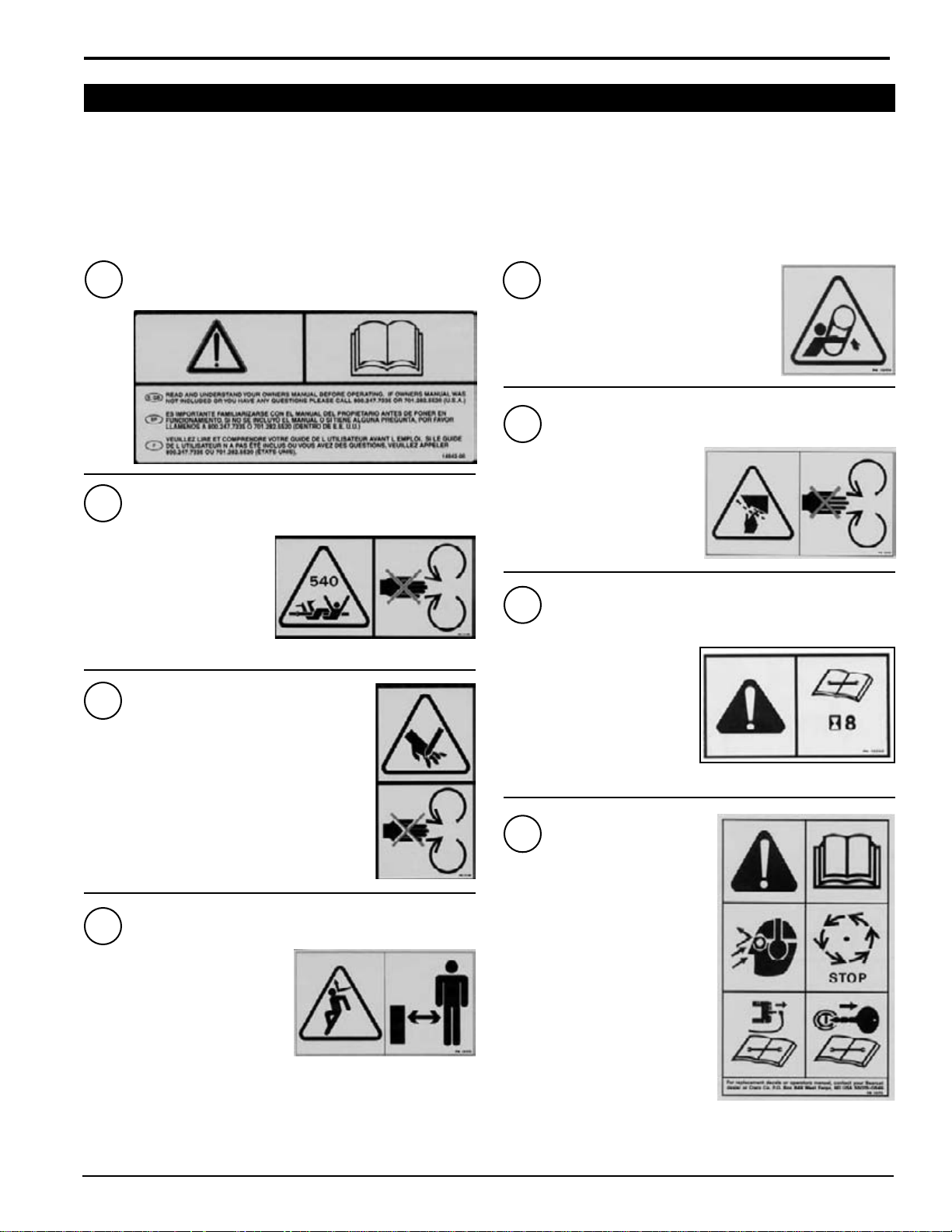
SAFETY
See Section 1.10 for decal locations. Familiarize yourself with all of the safety and operating decals on the machine
and the associated hazards. See the engine owners manual or contact the engine manufacturer for engine safety
instructions and decals. make certain that all safety and operational decals on this machine are kept clean and in good
condition. Refer to the parts catalog if you need a replacement decal. Decals that need replacement must be applied to
their original locations.
Pn 12174
1
2
CONTACT WITH ROTATING
DRIvELINE CAN CAuSE DEATH.
DO NOT OpERATE WITHOuT
ALL DRIvELINE, TRACTOR AND
EQuIpmENT SHIELDS IN pLACE.
ENSuRE THE DRIvELINE IS
SECuRELy ATTACHED AT BOTH
ENDS AND DRIvELINE SHIELDS
THAT TuRN FREELy ON THE
DRIvELINE ARE IN pLACE.
3
kEEp HANDS AND FEET OuT OF INLET AND
DISCHARGE OpENINGS WHILE mACHINE IS
OpERATING TO AvOID SERIOuS pERSONAL INjuRy.
STOp AND ALLOW mACHINE TO COmE TO A COmpLETE
STOp BEFORE CLEARING OBSTRuCTIONS.
Pn 12168
Pn 12168
DO NOT OpERATE mACHINE WITHOuT SHIELDS IN
pLACE. FAILuRE TO DO SO mAy CAuSE SERIOuS
INjuRy OR DEATH.
kEEp HANDS AND FEET OuT
OF INLET AND DISCHARGE
OpENINGS WHILE mACHINE IS
OpERATING TO AvOID SERIOuS
pERSONAL INjuRy. STOp AND
ALLOW mACHINE TO COmE TO
A COmpLETE STOp BEFORE
CLEARING OBSTRuCTIONS.
CHECk BLADE BOLTS FOR
pROpER TORQuE AFTER EvERy
8 HOuRS OF OpERATION.
CHECk BLADES AND ROTATE
OR RESHARpEN DAILy OR AS
REQuIRED TO kEEp BLADES
SHARp. REFER TO OWNERS
mANuAL FOR INSTRuCTIONS.
FAILuRE TO DO SO mAy CAuSE
pOOR pERFORmANCE, DAmAGE
OR pERSONAL INjuRy AND WILL
vOID THE mACHINE WARRANTy.
5
6
7
Pn 12174
Pn 12175
P/n 12175
P/n 12250
Pn 12250
Pn 12173
Pn 12173
4
DON NOT OpERATE THIS EQuIpmENT
IN THE vICINITy OF BySTANDERS.
DO NOT ALLOW CHILDREN TO
OpERATE THIS EQuIpmENT. ALWAyS
STAND CLEAR OF DISCHARGE AREA
WHEN OpERATING THIS mACHINE.
kEEp FACE AND BODy AWAy FROm
DISCHARGE AREAS.
8
READ AND uNDERSTAND THIS
OWNER/OpERATORS mANuAL. BE
COmpLETELy FAmILIAR WITH THE
CONTROLS AND THE pROpER uSE
OF THIS EQuIpmENT
OBTAIN AND WEAR SAFETy GLASSES
AND uSE HEARING pROTECTION AT
ALL TImES WHEN OpERATING THIS
mACHINE.
BEFORE INSpECTING OR SERvICING
ANy pART OF THIS mACHINE, SHuT
OFF pOWER SOuRCE, DISCONNECT
SpARk pLuG WIRE FROm SpARk
pLuG AND mAkE SuRE ALL mOvING
pARTS HAvE COmE TO A COmpLETE
STOp.
4.5 INCH CHIPPER
P/n 12172
Pn 12172
7
Page 10
SAFETY
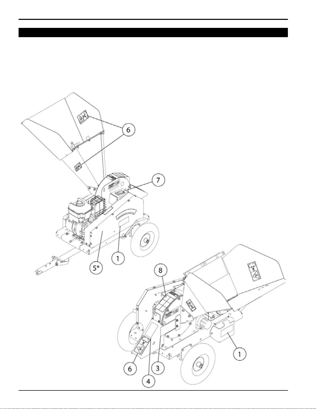
1.10 SafeTY decal locaTionS
The numbers below correspond to the decals in Section 1.9. Familiarize yourself with all of the safety and operational
decals on the machine and the associated hazards. See the engine owners manual or contact the engine manufacturer
for engine safety instructions and decals. make certain that all safety and operating decals on this machine are kept
clean and in good condition. Refer to the parts catalog if you need a replacement decal. Decals that need replacement
must be applied to their original locations.
1.10.1 modelS 77412, 77412S ("S" model ShoWn)
*DECal 5, #12174, Is loCatED
uNDERNEatH tHE bElt guaRD.
8
4.5 INCH CHIPPER
Page 11
SAFETY
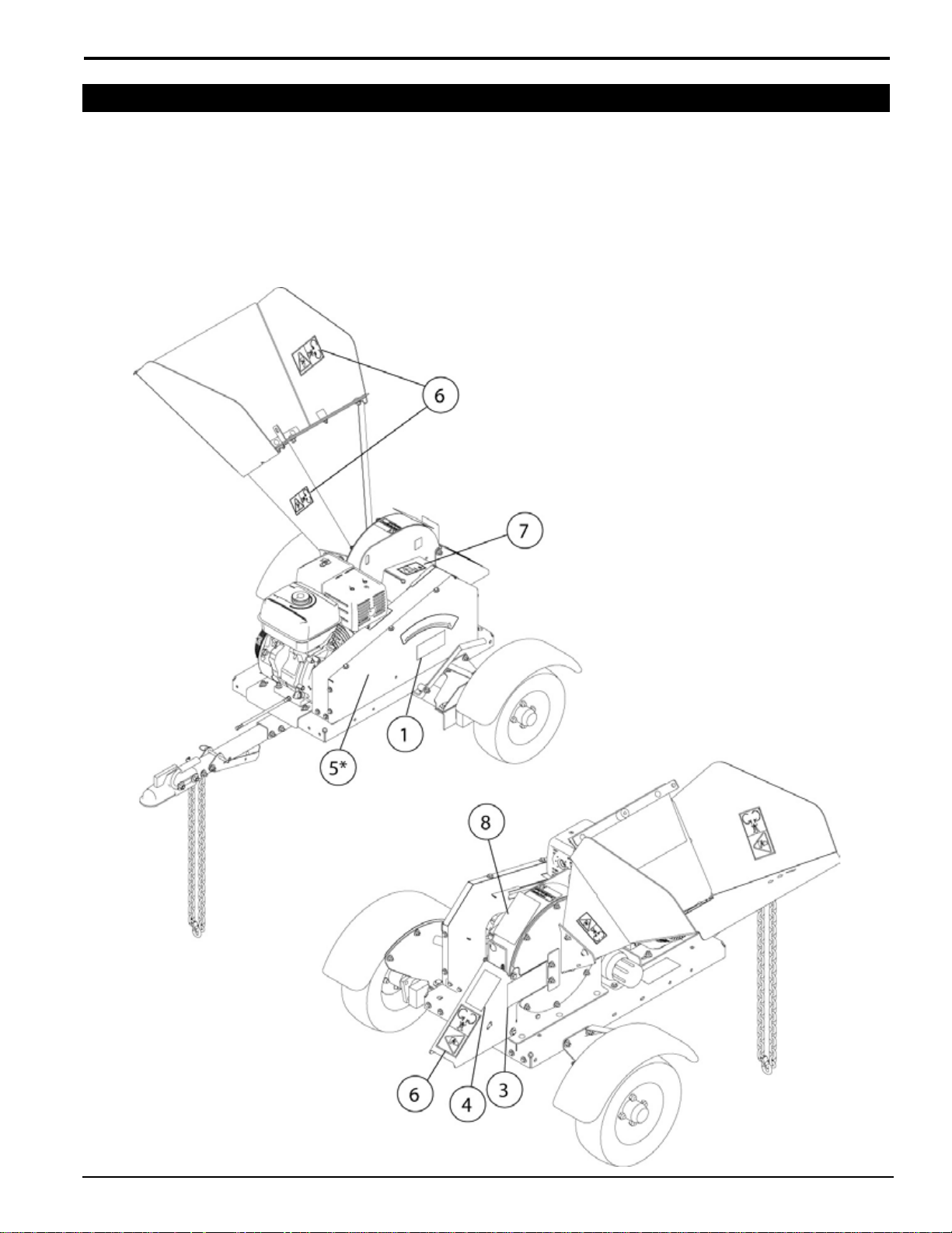
1.10 SafeTY decal locaTionS
The numbers below correspond to the decals in Section 1.9. Familiarize yourself with all of the safety and operational
decals on the machine and the associated hazards. See the engine owners manual or contact the engine manufacturer
for engine safety instructions and decals. make certain that all safety and operating decals on this machine are kept
clean and in good condition. Refer to the parts catalog if you need a replacement decal. Decals that need replacement
must be applied to their original locations.
1.10.2 modelS 77413, 77413S ("S" model ShoWn)
*DECal 5, #12174, Is loCatED
uNDERNEatH tHE bElt guaRD.
4.5 INCH CHIPPER
9
Page 12
SAFETY
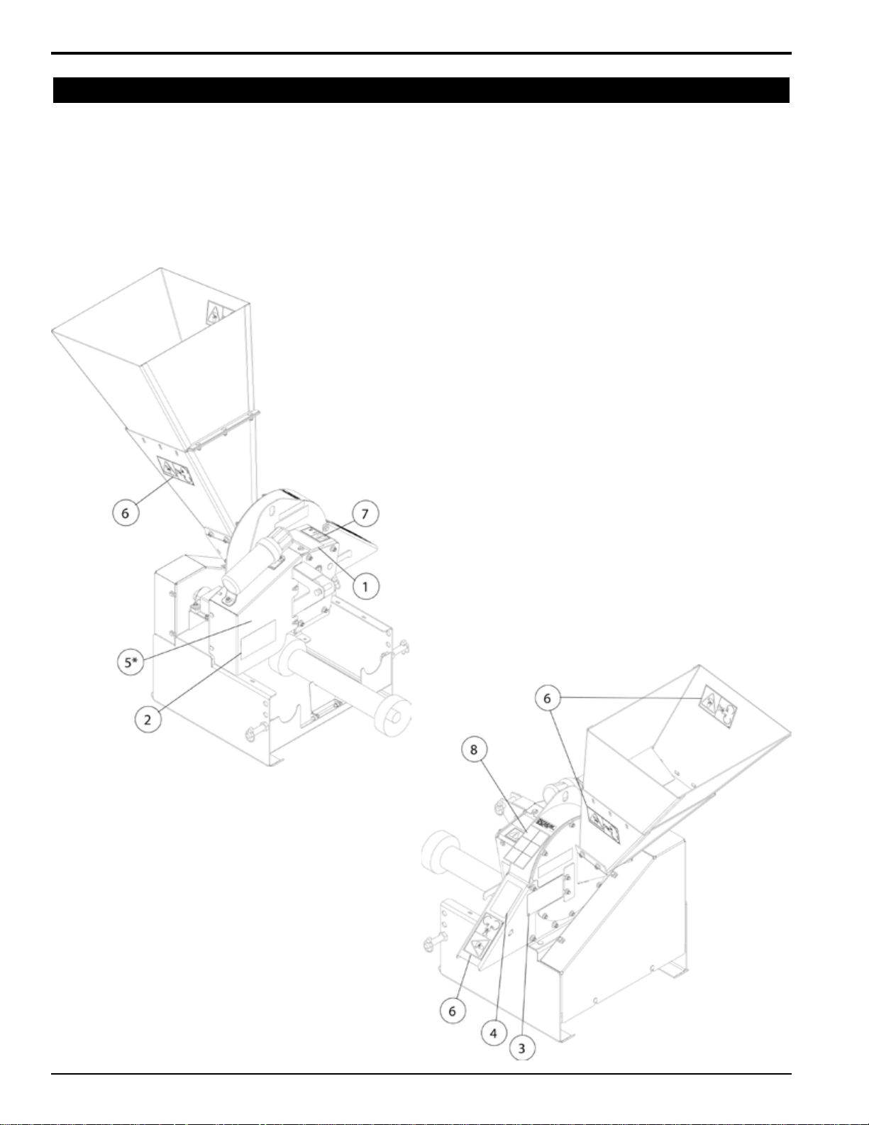
1.10 SafeTY decal locaTionS
The numbers below correspond to the decals in Section 1.9. Familiarize yourself with all of the safety and operational
decals on the machine and the associated hazards. See the engine owners manual or contact the engine manufacturer
for engine safety instructions and decals. make certain that all safety and operating decals on this machine are kept
clean and in good condition. Refer to the parts catalog if you need a replacement decal. Decals that need replacement
must be applied to their original locations.
1.10.3 modelS 77454, 77454S ("S" model ShoWn)
*DECal 5, #12174, Is loCatED
uNDERNEatH tHE bElt guaRD.
10
4.5 INCH CHIPPER
Page 13
2
Section
aSSemblY
Warning
Before inspecting or servicing any part of this machine,
shut off power source, disconnect spark plug wire from
spark plug and make sure all moving parts have come
to a complete stop.
Warning
If any bolts or nuts are dropped in the machine, be sure
to remove them before starting the machine. Remove
items from the shredder area by removing the discharge
screen.
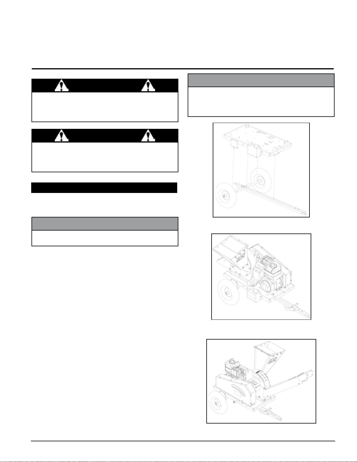
2.1 Trailer aSSemblY (342cc modelS)
Attach both axles to the hitch pole using two 5/16"
1.
u-bolts, washers and locknuts.
noTe
The wheel base is adjustable from 36" to 46".
noTe
The optional trailer conguration with the discharge tube
is optimal for discharging material into a pickup bed. The
standard conguration is used when discharging material
directly to the ground.
Figure 1, standard trailer/hitch assembly
(Models 77412, 77412s)
Slide a wheel onto the axle and secure with a 5/8"
2.
washer and cotter pin. Repeat for the remaining
wheel.
position the trailer onto the axle using a hoist or
3.
jack:
Standard configuration (figures 1 & 2): The
a.
axle and wheels should be positioned at the end
farthest away from the engine. Secure the trailer
to the hitch pole using two 3/8" x 1" carriage bolts,
3/8" washers and 3/8" nuts. The axle mounting
brackets located on each side of the trailer are
already mounted in the correct spot. Attach the
axles to the axle brackets using two 5/16" u-bolts,
washers and locknuts.
optional configuration (figure 3): move the
b.
axle mounting brackets on the side of the trailer to
the holes closest to the engine. Attach the trailer
to the hitch pole using two 3/8" x 1" carriage bolts,
3/8" washers and 3/8" nuts. Attach the axles to the
axle brackets using two 5/16" u-bolts, washers
and locknuts.
Attach the hitch pole plate to the front of the hitch
4.
pole using two 3/8" x 1" bolts, 3/8" washers and 3/8"
nuts.
Figure 2, standard trailer configuration
(Models 77412, 77412s)
Figure 3, optional trailer configuration
(Models 77412, 77412s)
4.5 INCH CHIPPER
11
Page 14

ASSEMBLY
2.2.1 lighTS
If assembling 390CC models to the optional conguration shown in Figure 7, move the trailer lights by following
these steps:
1. Remove the bolts connecting the RH and LH light
brackets to the trailer.
2. Disconnect the trailer light wiring harness from the
lights by pushing a punch into the wire release hole
(Figure 4).
3. Cross the taillights and attach them to the other end of
the trailer. make sure the right tail light is attached to
the right side of the trailer, and the left light is on the
left side.
4. Reconnect the wiring harness.
5. Test the blinker and brake lights to ensure the wiring
is properly connected.
optional configuration (figure 7): Locate the
b.
holes on the sides of the trailer closest to the
engine. Align these holes with the top holes on the
axle support brackets located on the axle. Attach
with one 3/8" x 1" bolt and one 3/8" x 1-1/4" bolt
on each side.
noTe
The optional trailer conguration with the discharge tube
is optimal for discharging material into a pickup bed. The
standard conguration is used when discharging material
directly to the ground.
Figure 4, Disconnecting the wiring harness
2.2.2 aXle and Wheel aSSemblY
Attach the fender weldment to the fender mount with
1.
two 5/16" x 1" bolts and one 5/16" x 3/4" bolt. Attach the
fender mount to the axle with two 1/2" x 1-1/4" bolts.
Slide a wheel onto the hub. Install four 1/2" nuts and
2.
tighten to 75 Ft-lb. Repeat for the other wheel.
position the trailer onto the axle using a hoist or
3.
jack:
Standard configuration (figure 5 & 6): Locate
a.
the holes on the sides of the trailer farthest from
the engine. Align these holes with the top holes
on the axle support brackets located on the axle.
Attach with one 3/8" x 1" bolt and one 3/8" x 1-1/4"
bolt on each side.
Figure 5, standard trailer/hitch assembly
(Models 77413, 77413s)
Figure 6, standard trailer configuration
(Models 77413, 77413s)
Figure 7, optional trailer configuration
(Models 77413, 77413s)
12
4.5 INCH CHIPPER
Page 15

ASSEMBLY
2.2 Trailer aSSemblY (conT.)
2.2.3 hiTch aSSemblY
Attach the hitch channel to the bottom of the trailer:
1.
Standard configuration (figures 5 & 6): Attach
a.
the hitch channel on the end closest to the engine
using two 3/8" carriage bolts, washers and nuts.
optional configuration (figure 7): Attach the
b.
hitch channel on the end farthest from the engine
using two 3/8" carriage bolts, washers and nuts.
Attach the coupler and the coupler handle (not used
2.
on 77413S) onto the hitch pole using two 1/2" x 3-1/4"
bolts, 1/2" washers and 1/2" nuts (Figure 8).
Attach the safety chains, one on each side of the hitch
3.
pole, using one 3/8" x 3-1/2" bolt, four washers (one
on each side of both safety chains) and one nut.
Attach the nylon lanyard to the hitch pole using one
4.
1/4" x 3/4" bolt and 1/4" locknut. Attach a hitch pin to
the lanyard.
Attach the jack stand to the hitch pole using one 3/8"
5.
x 3" bolt, 3/8" washer and 3/8" nut. use a hitch pin to
secure the jack in the raised position.
2.3 diScharge aSSemblY
2.3.1 diScharge caP
move the chipper deflector weldment located inside the
1.
chipper housing to the down position (Figure 9).
Slide the discharge cap onto the chipper housing,
2.
ensuring that the weldment bolts fit in the notches on
the disk cover (Figure 10). Install two 5/16" serrated
flange nuts on the weldment bolts.
Insert two 3/8" x 5-1/2" bolts into the bolt holes on the
3.
chipper housing and tighten using 3/8" washers and
3/8" nylock nuts.
Insert the hitch pole into the hitch channel and attach
6.
using one 3/8" x 3" bolt, washer and nut. Secure with
a hitch pin.
Figure 9, Chipper deflector weldment
Figure 10, Discharge cap
Figure 8, Hitch assembly
2.3.2 diScharge Tube (oPTional)
move the chipper deflector weldment located inside
1.
the chipper housing to the up position (Figure 9).
4.5 INCH CHIPPER
13
Page 16

ASSEMBLY
2.5 chuTe eXTenSion2.3 diScharge aSSemblY (conT.)
Slide the discharge tube onto the chipper housing
2.
ensuring that the weldment bolts fit securely into the
notches on the disk cover (Figure 11). Tighten using
5/16" flange nuts.
Insert two 3/8" x 5-1/2" bolt into the bolt holes on the
3.
chipper housing and tighten using 3/8" washers and
3/8" nylock nuts.
2.5.1 eXTenSion TraY (77412S, 77413S)
Attach the chipper chute flap and flap retainer to the
1.
chute with two 3/8" x 1" carriage bolts through the
outside holes. Install the rubber bumper to the center
hole with a 1/4" x 1-1/2" screw, washer and nut (Figure
13).
Attach the extension hinge to the chipper chute with
2.
three 3/8" x 1" carriage bolts, washers and nuts.
position the lips of the extension tray behind the lips of
3.
the chipper chute. Slide the chute extension tray over
the chipper chute. Align the four bolt holes in the chute
extension tray with the bolt holes in the hinge.
Insert four 3/8" x 1" carriage bolts through the tray and
4.
extension hinge. Secure the bolts with 3/8" washers
and nuts.
Connect the hinge latch to the bottom of the extension
5.
tray with two 5/16" x 3/4" carriage bolts, washers and
nuts.
Figure 11, optional discharge tube
2.4 chuTe aSSemblY
Attach the chipper chute to the chipper housing using four
3/8" x 1" carriage bolts, washers and locknuts (Figure
12). use two bolts on each side. Install with nuts on the
outside.
Figure 13, Extension tray
14
Figure 12, Chipper chute
4.5 INCH CHIPPER
Page 17

ASSEMBLY
2.5 chuTe eXTenSion (conT.)
2.5.1 chuTe eXTenSion (77454S)
Attach the chipper chute extension to the chipper chute
using six 3/8" x 1" carriage bolts, 3/8" washers and 3/8"
nuts (Figure 14). use three bolts on each side.
2.7 checking fluidS (engine modelS)
2.7.1 checking/adding moTor oil
Check the oil level. If needed, fill the engine with the type
and amount of oil specified in the engine owner's manual.
Figures 15 and 16 show the oil fill locations for both Briggs
& Stratton and Honda engines.
Figure 14, Chipper chute extension
2.6 baTTerY inSTallaTion (342cc modelS)
The battery is mounted on the side of the chipper in front
of the engine. Only use batteries that meet or exceed the
following specifications:
battery category, lawn and garden
bci group Size u1
200-250 cca
7-3/4" X 5-3/16" X 7-5/16"
Suggested Source:
exide cutting edge, Type gT-h
Warning
To avoid sparks and a possible explosion or fire due to
a short circuit:
Do not touch the positive (+) battery terminal with tools,
jewelry or other metal objects.
When installing battery cables, connect the positive (+)
cable first and the negative (-) cable last.
Figure 15, briggs oil fill (located on each side of engine)
4.5 INCH CHIPPER
Figure 16, Honda oil fill
15
Page 18

ASSEMBLY
2.7 checking fluidS (conT.)
danger
Gasoline is highly flammable and its vapors are explo-
sive. To prevent personal injury or property damage:
Store gasoline only in approved containers, in well
ventilated, unoccupied buildings, away from sparks or
flames. Do not fill the fuel tank while the engine is hot
or running. Spilled fuel could ignite if it comes in contact
with hot parts or sparks from ignition. Do not start the
engine near spilled fuel. Never use gasoline as a cleaning
agent.
2.7.2 filling The fuel Tank
For best results use only clean, fresh, unleaded gasoline
with a pump octane rating of 86 or higher or a research
octane rating of 91 or higher.
purchase gasoline in small quantities and store in
clean, approved containers. DO NOT mIx OIL WITH
GASOLINE.
ethanol
Gasohol (up to 10% ethyl alcohol, 90% unleaded gasoline
by volume) is an approved fuel. Other gasoline/alcohol
blends are not approved.
mTbe
methyl Tertiary Butyl Ether (mTBE) and unleaded gasoline
blends (up to a maximum of 15% mTBE by volume) are
an approved fuel for engine models. Other gasoline/ether
blends are not approved.
methanol
methanol (up to a maximum of 5% volume) is an approved
fuel. methanol blends must contain cosolvents and
corrosion inhibitors to protect the fuel system. Gasoline
containing more than 5% methanol may cause engine
problems.
imPorTanT
Do not attempt to start the engine at this time. Wait until
you have read the complete starting instructions in the
Operation Section of this manual.
2.8 driveline connecTion (PTo modelS)
Attach chipper to tractor with three-point hitch. Adjust
1.
the chipper up and down to find the shortest distance
between the chipper rotor shaft and tractor pTO.
pull the driveline into two pieces. Connect one end to the
2.
tractor pTO and the other end to the chipper rotor shaft.
Line up the two halves parallel to each other. If the shaft
of one half extends past the end shield of the other half
as seen in the illustration below, you will need to shorten
the driveline. if your driveline is not too long, slide
the two ends together and skip to step 7.
3.
measure the distance from the end of the driveline tube
to the bottom of the end shield of the other driveline half
(dimension “A” in Figure 17). measure and mark the
driveline tube 1-9/16” inward from dimension “A.”
Cut the shield tube in the marked position.
4.
using the cut piece of shield tube as your measure-
5.
ment, place the cut piece against the end of the shaft.
mark and cut the shaft.
Repeat step 5 for the other half of the driveline, file both
6.
shaft ends, and slide the two halves back together.
The longest distance between the tractor pTO and
7.
chipper rotor shaft must also be checked. If the longest
distance exceeds 24.5", contact your dealer to obtain
a longer pTO shaft.
When you have confirmed that your pTO shaft is the
8.
proper length, connect the driveline to the chipper rotor
shaft using key stock and two set screws contained in
the owner’s kit.
Connect the opposite end of the pTO shaft to the tractor.
9.
To add gasoline
Stop engine, wait for all parts to stop moving and
1.
disconnect spark plug wire. Remove key from key
switch. Allow the engine and muffler to cool for at least
three minutes.
Clean area around fuel fill cap and remove cap.
2.
using a clean funnel, fill fuel tank to 1/2" below bottom
3.
of filler neck to provide space for any fuel expansion.
Install fuel fill cap securely and wipe up any spilled
gasoline.
16
Figure 17, shortening the driveline
4.5 INCH CHIPPER
Page 19

3
conTrolS & oPeraTion
Section
3.1 engine model conTrolS
3.1.1 chiPPer conTrolS
hitch: On 390CC models, always use 2 inch (50 mm)
1.
ball and safety chains.
Jack stand: Always have in up position and clear from
2.
ground when moving. When in use, place in DOWN
position on a level surface.
belt guard: Never remove guards when chipper is
3.
in use.
rotor access cover: Remove to expose chipper
4.
blades.
discharge cap: Chipped materials exit through the
5.
discharge cap. A discharge tube is an available alternative.
chipper chute: Feed materials to be chipped through
6.
the chipper chute.
chipper engagement lever: pull lever up for start
7.
position. push lever down for chipping position.
cauTion
Wear safety glasses at all times when operating the
machine. Do not wear loose tting clothing. The operator should always wear heavy boots, gloves, pants and
shirt. use common sense and practice safety to protect
yourself from branches, sharp objects and other harm-
ful objects.
noTe
The heavy rotor will continue to turn for some time after
the engine or tractor has been shut off. you can tell
that the rotor has stopped when no noise or machine
vibration is present. Inserting a branch into the chipper
chute to contact the blades will slow the rotor and shorten
stopping time.
Figure 18, Chipper controls (engine models)
4.5 INCH CHIPPER
17
Page 20

CONTROLS & OPERATION
3.1 engine model conTrolS (conT.)
noTe
For more detailed engine information, see the engine
owners manual provided with the chipper.
3.1.2 engine conTrolS
engine choke: use when starting a cold engine. push
1.
lever to ON position when starting. push to OFF position when engine is running. Full choke may not be
necessary when starting a warm engine. In this case,
partial or no choke may work best.
fuel cut-off switch: push lever to the ON position to
2.
start and run engine.
engine throttle: Changes engine speed. push lever
3.
all the way to the ON position for full throttle operation.
push the opposite way for engine idle. push all the way
to the OFF position to shut engine off. Refer to engine
manual for further engine operating instructions.
Starter cord: To start, pull the cord until light resis-
4.
tance is felt and then pull briskly.
engine switch: Turn to ON position to start and run
5.
engine. To stop, turn to OFF position.
fuel tank: use unleaded gasoline with a pump octane
6.
rating of 86 or higher or a research octane rating of
91 or higher. Do not mix with oil. 10 percent ethanol,
15 percent mTBE, or 5 percent methanol blends are
acceptable.
Figure 20, 390CC Honda controls
18
Figure 19, 342CC briggs & stratton controls
4.5 INCH CHIPPER
Page 21

3.2 PTo model conTrolS
Three point hitch connection: mounts chipper to
1.
tractor three point hitch.
2.
PTo shaft: Connects chipper to tractor pTO shaft.
Avoid driveline angles over 20 degrees on pTO shaft
when unit is in use. NOTE: minimum and maximum
telescoping on the pTO shaft is 18.11" to 24.49". This
will leave a 6.43" overlap. See Section 2.4 for instructions on checking shaft length.
forward belt shield
3.
ley.
front belt shield: Covers the pTO driven pulley.
4.
5.
belt engagement lever: push the lever down for chip
ping position. pull the lever up for neutral position.
chipper chute
6.
the chipper chute.
7.
rotor access cover
blades.
discharge cap
8.
discharge cap. A discharge tube is an available alternative.
: Covers the chipper drive pul-
: Feed materials to be chipped through
: Remove to expose chipper
: Chipped materials exit through the
CONTROLS & OPERATION
cauTion
Wear safety glasses at all times when operating the
machine. Do not wear loose tting clothing. The operator should always wear heavy boots, gloves, pants and
shirt. use common sense and practice safety to protect
yourself from branches, sharp objects and other harm-
ful objects.
noTe
The heavy rotor will continue to turn for some time after
the engine or tractor has been shut off. you can tell
that the rotor has stopped when no noise or machine
vibration is present. Inserting a branch into the chipper
chute to contact the blades will slow the rotor and shorten
stopping time.
Figure 21, Chipper controls (Pto models)
4.5 INCH CHIPPER
19
Page 22

CONTROLS & OPERATION
3.3 STarTing
cauTion
move the machine to a clear, level area outdoors before
starting. Do not operate in the vicinity of bystanders. make
sure the cutting chamber is empty before starting.
3.3.1 STarTing elecTric modelS
Do not crank the engine continuously for more than 10
seconds at a time. If the engine does not start, allow a
60 second cool down period between starting attempts.
Failure to follow these guidelines can burn out, or
permanently damage, the starter motor.
If the engine develops sufficient speed to disengage
the starter but does not keep running (a false start), the
engine rotation must be allowed to come to a complete
stop before attempting to restart the engine. If the starter
is engaged while the flywheel is rotating, damage to the
starter may result.
If the starter does not turn the engine over, shut off starter
immediately. Do not make further attempts to start the
engine until the condition is corrected. Do not jump start
using another battery. Follow the steps below to start the
machine.
3.3.2 STarTing recoil modelS
move the machine to a clear, level area outdoors before
starting. Do not operate in the vicinity of bystanders. make
sure the cutting chamber is empty before starting.
Check engine oil level before starting.
1.
Turn the fuel cut-off switch to the ON position.
2.
Turn the engine switch to the ON position.
3.
place the throttle control midway between the SLOW
4.
and FAST positions. place the choke control into the
CHOkE position.
place the chipper engagement lever in the START
5.
position.
pull the recoil starter until the engine starts. make sure
6.
the starting cord retracts.
move the choke to the RuN position.
7.
for a cold engine - gradually return the choke to the
OFF position after the engine starts and warms up.
The equipment may be operated during the warm up
period, but it may be necessary to leave the choke
partially on until the engine warms up.
Check engine oil level before starting.
1.
place the throttle control midway between the SLOW
2.
and FAST positions. move the choke control to the
CHOkE position.
Turn the fuel cut-off switch to the ON position.
3.
place the chipper engagement lever in the START
4.
position.
push the engine switch to START. Release after en-
5.
gine starts.
move the choke to the RuN position.
6.
for a cold engine: Gradually return the choke control
to the OFF position after the engine starts and warms
up.
The equipment may be operated during the warm up
period, but it may be necessary to leave the choke
partially on until the engine warms up.
for a warm engine: Return choke to the OFF position
as soon as engine starts.
move the throttle to the FAST position and place the
7.
chipper engagement lever in the CHIppING position.
for a Warm engine - Return choke to the OFF posi-
tion as soon as engine starts.
move the throttle to the FAST position and place the
6.
chipper engagement lever in the CHIppING position.
3.3.3 STarTing PTo modelS
If the tractor is able to start the chipper with the chipper
1.
engagement lever in the CHIppING position, it is not
required to place the chipper engagement lever in the
START position when starting the tractor pTO. If the
tractor pTO cannot start the chipper with the chipper
engagement lever in the CHIppING position, move the
chipper engagement lever to the START position.
Start the tractor engine and engage the tractor pTO.
2.
move the chipper engagement lever to the CHIppING
3.
position and increase the engine speed to the rated
pTO Rpm position.
20
4.5 INCH CHIPPER
Page 23

3.4 SToPPing
3.4.1 SToPPing elecTric/recoil modelS
move the throttle to the SLOW position.
1.
move the chipper engagement lever to the START
2.
position.
Allow the engine to run at idle for 30-60 seconds; stop
3.
the engine by moving the throttle to the STOp position
or turning off the ignition.
Allow machine to come to a complete stop.
4.
3.4.2 SToPPing PTo modelS
If the tractor is able to stop the chipper with the chipper
1.
engagement lever in the CHIppING position, it is not
required to place the chipper engagement lever in the
START position when stopping the tractor pTO. If the
tractor pTO cannot stop the chipper with the chipper
engagement lever in the CHIppING position, move the
chipper engagement lever to the START position.
CONTROLS & OPERATION
Do not lean over the chipper chute to push objects
5.
into the cutting device. use a push stick or brush
paddle.
Never use shovels or forks to feed brush. They can
6.
be chipped, are expensive to replace, and cause
extensive damage. In addition, metal pieces can be
ejected from the chipper chute and cause serious
injury or death.
Never feed brush into the chipper chute with your
7.
feet.
place limb, butt end first, into the chipper chute until
8.
it contacts the chipper blades. The actual feed rate
of the limb into the chipper will depend on the type of
material fed and sharpness of the cutting blades.
Stop the material feeding and allow the engine to re-
9.
cover if the engine slows to where it may stall.
Remove the branch and rotate it before reinserting it
10.
into the chute if the chipper jams.
Alternately insert and retract the limb or insert continu-
11.
ously at a rate that will not kill the engine.
move the tractor throttle to the SLOW position.
2.
Disengage the pTO lever and shut off the tractor
3.
engine.
Allow machine to come to a complete stop.
4.
Warning
allow the machine to come to complete stop before
inspection or servicing. The rotor is heavy and has
inertia built up that will allow the rotor to turn for some time
after the clutch has been disengaged. you can tell when
the rotor has come to a complete stop when there is no
noise or machine vibration present. you can reengage
the clutch to slow the rotor to a stop.
3.5 chiPPing
The Bear Cat chips a variety of materials into a more readily
decomposed or handled condition. The following guidelines
can help you get started.
Run unit at full operating speed before starting to chip
1.
material.
Select limbs that are up to 4-1/2 inches in diameter.
2.
Trim side branches that cannot be bent enough to feed
into the chipper chute. Hold small diameter branches
together in a bundle and feed in simultaneously.
Exclude pieces of metal, rocks, bottles, cans, and
3.
other foreign objects when feeding chipable material
into the machine.
Feed brush from the side of the chipper chute, rather
4.
than from the front. Step aside to avoid being hit by
the brush moving into the chipper.
Chipping dead, dry material will create heat and dull
12.
the chipping blades quickly.
Alternate green material with dry material to lubricate
13.
the chipping blades for longer life and better performance.
The chipping blades will become dull and will require
14.
periodic sharpening. Refer to the Service and maintenance section for sharpening instructions.
3.6 aTTaching/unhooking chiPPer
modelS: 77413, 77413S
The machine is closely balanced. Do not lift higher than
necessary to prevent tipping the machine over. Refer to
Figure 4.1 when hooking and unhooking the chipper.
aTTaching:
Open the coupler latch.
1.
Raise the trailer hitch until the coupler is above the
2.
height of the hitch ball on the towing vehicle.
Lower the trailer hitch until the coupler fully engages
3.
the hitch ball.
Close the coupler latch, securing the coupler to the
4.
hitch ball.
Install the hitch pin through the coupler latch.
5.
Cross the safety chains under the hitch and connect
6.
to towing vehicle.
4.5 INCH CHIPPER
21
Page 24

CONTROLS & OPERATION
3.6 aTTaching/unhooking (conT.)
Raise the jack stand and secure it to the hitch using
7.
a hitch pin.
Connect the trailer wire harness to the towing vehicle.
8.
Test the trailer lights to ensure they are functioning
properly.
unhooking:
unhook the safety chains (Figure 22) from the towing
1.
vehicle. Latch safety chains to the hitch to prevent them
from interfering with chipping.
Remove the hitch pin from the coupler latch.
2.
unlatch the coupler and disconnect the hitch coupler
3.
from the hitch ball.
move the hitch of the chipper away from the hitch ball
4.
and lower the jack stand. Secure with a hitch pin.
Figure 22, trailer hitch (Models 77413, 77413s)
22
4.5 INCH CHIPPER
Page 25

4
Service & mainTenance
Section
4.1 mainTenance Schedule
The items listed in the service and maintenance schedule are to be checked, and if necessary, corrective action taken.
This schedule is designed for units operating under normal conditions. If the unit is operating in adverse or severe usage
conditions it may be necessary for the items to be checked and serviced more frequently.
See engine owners manual for further maintenance and troubleshooting information.
Service and mainTenance Schedule
freQuencY
comPonenT
ENGINE OIL CHECk OIL LEvEL
FuEL TANk FILL
AIR CLEANER CHECk & CLEAN
AIR INTAkE CLEAN
NuTS & BOLTS CHECk
CHIppER BLADES
BELT TENSIONER
pIvOT
pTO CROSS
jOuRNALS
pTO INNER TuBES GREASE
pTO SHIELD
BEARINGS
pRE-CLEANER
ELEmENT
BELT/puLLEy
ALIGNmENT
BELT CONDITION CHECk
TIRE pRESSuRE CHECk
ENTIRE mACHINE CLEAN
ROTOR BEARING GREASE
SAFETy SWITCH CHECk
ENGINE OIL CHANGE
COOLING
SHROuDS
SpARk pLuG
STARTER DRIvE SERvICE
SOLENOID SHIFT
STARTER
FuEL FILTER REpLACE
BATTERy
CONNECTIONS
1
perform more frequently in dusty, dirty or severe usage conditions.
2
Have a Briggs or Honda engine service dealer perform this service.
3
It is a good sign that your chipper blades need sharpening when material stops self feeding.
mainTenance
reQuired
1
CHECk, SHARpEN
IF NEEDED
GREASE
GREASE
GREASE
CLEAN
CHECk
CLEAN
CHECk CONDITION
AND GAp
DISASSEmBLE AND
CLEAN
CHECk
3
1
1
1
2
2
before
each uSe
1
everY
8
hrS
everY
25
hrS
everY
50
hrS
everY
100 hrS
everY
200 hrS
everY
500 hrS
everY
1500 hrS
4.5 INCH CHIPPER
23
Page 26

SERVICE & MAINTENANCE
Warning
DISCONNECT SpARk pLuG WIRE FROm SpARk pLuG AND mAkE SuRE ALL mOvING pARTS HAvE COmE TO A COmpLETE STOp.
4.2 inSTalling The diSk lock
When working on the disk assembly, use the lock
mechanism at all times (Figure 23). Follow the steps below
to install the disk lock:
Remove the chipper deflector.
1.
Rotate the chipper disk until the hole on the chipper
2.
paddle is aligned with the hole on the chipper housing
(Figure 23).
Install a punch or screwdriver into the holes.
3.
One of the 3/8" x 5-1/2" bolts from the chipper deflector
can also be used to lock the disk.
BEFORE INSpECTING OR SERvICING ANy pART OF THIS mACHINE, SHuT OFF pOWER SOuRCE,
Severe vibration when feeding material into the chip-
1.
per.
Small diameter branches do not self-feed.
2.
Chips discharge unevenly or have stringy tails, espe-
3.
cially when chipping green branches.
Before you sharpen the chipping blades, check for
permanent damage. Replace the blade if:
There are cracks, broken corners or nicks greater than
1.
1/8" (Figure 24).
The base of the cutting edge is worn or has been re-
2.
noTe
sharpened so that the edge extends less than 1/16"
above the rotor chipping slot.
Figure 23, Disk lock
4.3 chiPPer bladeS
Warning
Chipping blades are sharp! use caution when working
on machine to avoid injury.
The chipper blades will eventually become dull, making
chipping difficult and adding extra strain on the machine.
poor chipping performance is usually a result of dull
chipping blades. It is recommended that the blades
be sharpened every 5-15 hours, or if your chipper’s
performance has decreased. Check for the following
symptoms and sharpen the blades if needed:
Figure 24, Causes for replacement
4.3.1 removing The bladeS
Remove the chipper deflector from the chipper hous-
1.
ing by removing the two 3/8" x 5-1/2 bolts securing
the discharge cap or optional discharge tube to the
chipper housing and loosening the 5/6" flange nuts
on the weldment bolts. Remove the discharge cap or
optional discharge tube.
Install the disk lock (Section 5.2). The disk is now
2.
restrained for removing the blades. To access the
remaining blade, remove the punch or screwdriver,
reposition the disk and return the punch or screwdriver
to the disk lock hole.
Remove the two 1/2" security lock nuts (on back side
3.
of chipper disk) and the two 1/2" x 1-3/4" flat head
screws holding the blade to the disk. Repeat for the
remaining blade.
Inspect blades to see if cracks or nicks are visible.
4.
If cracks are present, replace the blades. Replace
the blade if nicks cannot be removed by sharpening.
Tighten screws to 120 ft-lbs.
24
4.5 INCH CHIPPER
Page 27

SERVICE & MAINTENANCE
MOUNTING SURFACE
DO NOT GRIND
MOUNTING SURFACE
DO NOT GRIND
SHARPENED
SURFACE
SHARPENED
SURFACE
45˚
.38
Warning
DISCONNECT SpARk pLuG WIRE FROm SpARk pLuG AND mAkE SuRE ALL mOvING pARTS HAvE COmE TO A COmpLETE STOp.
BEFORE INSpECTING OR SERvICING ANy pART OF THIS mACHINE, SHuT OFF pOWER SOuRCE,
4.3 chiPPer bladeS (conT.)
4.3.2 SharPening The bladeS
To grind the angled edge of the chipping blade to 45
degrees (see Figure 25): Grind the blades on a slowspeed wet grinder if possible, or have them sharpened by
a professional. If you use a bench grinder, be careful when
grinding so that the blade material does not get too hot
and change color–this will remove the blade's special heat
treated properties. use short grinding times and cool with
water. Try to remove an equal amount from each blade to
maintain balance. Replace the chipping blades and tighten
screws to 120 ft-lbs. Close cover and replace bolt.
Figure 25, Double edged blade
4.3.3 inSTalling The bladeS
Warning
It is important to ensure that the minimum gap between
the chipping anvil and ALL chipping blades is 1/16". All
chipping blades should be rotated until even with the
chipping anvil and then measured. Failure to do so can
result in the chipping blades striking the chipping anvil,
causing serious injury or death.
Adjust the anvil by loosening the 5/16" x 5/8" bolts
3.
holding the anvil to the disk cover and sliding the anvil
inward or outward until the desired measurement is
achieved.
Torque the bolts to 17 Ft-lbs.
4.
Rotate the rotor to ensure the remaining blade clears
5.
the anvil by 1/16" to 1/8".
If the chipper chute was removed, reinstall it.
6.
noTe
If the chipping anvil edge is damaged or worn unevenly,
remove the three 5/16" bolts and washers holding the
anvil to the disk cover and use one of the other three
edges. Adjust for correct measurement.
Lock disk assembly (Section 4.2).
1.
place a blade on the disk and attach using two 1/2" x
2.
1-3/4" flat head screws and two 1/2" security lock nuts.
Torque the 1/2" security lock nuts to 120 Ft.-lb. Repeat
for the remaining blades.
Reinstall the chipper discharge cap or optional dis-
3.
charge tube (Section 2.3).
4.3.4 SeTTing chiPPing blade clearance
The chipping blades should clear the chipping anvil, located
directly under the chipper chute, by 1/16" to 1/8". Removing
the chipper chute is noT required for setting the chipping
blade clearance. However, removing the chipper chute
can provide better access for measuring the chipping
blade clearance. To adjust the blade clearance, proceed
as follows:
Rotate the disk until a chipping blade is even with the
1.
chipping anvil.
measure the amount of clearance between the chip-
2.
ping blade and chipper anvil from inside of the chipper
housing. The minimum distance between the chipping
blade and the chipping anvil should be 1/16" (Figure
26).
Figure 26, Chipper blade and anvil clearance
4.5 INCH CHIPPER
25
Page 28

SERVICE & MAINTENANCE
Warning
DISCONNECT SpARk pLuG WIRE FROm SpARk pLuG AND mAkE SuRE ALL mOvING pARTS HAvE COmE TO A COmpLETE STOp.
BEFORE INSpECTING OR SERvICING ANy pART OF THIS mACHINE, SHuT OFF pOWER SOuRCE,
4.4 drive belT adJuSTmenT
Check the condition of the drive belt(s) annually or after
every 25 hours of operation, whichever comes first.
Replace a cracked, frayed, worn or stretched drive belt.
Only replace drive belt with original banded type belt.
Do not use single type belts. To adjust the drive belt(s),
proceed as follows:
4.4.1 engine modelS
place the chipper engagement lever in the START
1.
position.
Shut engine off.
2.
Disconnect battery cables (electric start models).
3.
Remove the seven 5/16" x 3/4" bolts securing the
4.
belt shield to the shield weldment. Remove the belt
shield.
To increase tension on the belt, do the following:
5.
5a. Loosen the four carriage bolts attaching the
engine plate to the trailer.
5b. Locate the two 5/16" x 3" bolts and 5/16"
flange nuts located on the side of the chipper between the trailer and the engine plate
(Figure 27).
If the bolts and nuts between the engine plate and the
7.
trailer cannot be adjusted any further, and the tension
needs further adjustment, tighten the eyebolt until the
appropriate deflection is achieved.
Replace the belt if no adjustment is left (Section
8.
4.5).
Reinstall the belt shield.
9.
4.4.2 PTo modelS
move the engagement lever to the RELEASE posi-
1.
tion.
Disengage pTO and shut off tractor engine.
2.
Remove the pTO shaft from the tractor and disconnect
3.
from the 3 point hitch.
move the engagement lever to the CHIppING posi-
4.
tion.
Remove the 5/16" bolts to take off either the front or
5.
rear belt shield.
Either tighten or loosen the eyebolt at the base of the
6.
idler until the belt deflection is 7/16" when a 20 lb. load
is placed against the bolt.
5c. Tighten both 5/16" bolts equally to move the
engine away from the chipper housing until
the belt deflection is 7/16" when a 20 lb. load
is placed against the belt (Figure 28).
5d. Tighten the four carriage bolts securing the
engine plate to the trailer.
5e. Tighten both 5/16" flange nuts to ensure the
proper deflection is maintained.
To loosen tension on the belt, do the following:
6.
6a. Loosen the four carriage bolts attaching the
engine plate to the trailer.
6b. Loosen both 5/16" flange nuts.
6c. Loosen both 5/16" x 3" adjustment bolts
equally and push the engine plate against the
bolts. Loosen bolts until the belt deflection is
7/16" when a 20 lb. load is placed against the
belt (Figure 28).
6d. Tighten the four carriage bolts securing the
engine plate to the trailer.
6e. Tighten both 5/16" flange nuts to ensure the
proper deflection is maintained.
Reinstall belt shields.
7.
Figure 27, adjustment bolts
Figure 28, belt tension
26
4.5 INCH CHIPPER
Page 29

SERVICE & MAINTENANCE
Warning
DISCONNECT SpARk pLuG WIRE FROm SpARk pLuG AND mAkE SuRE ALL mOvING pARTS HAvE COmE TO A COmpLETE STOp.
BEFORE INSpECTING OR SERvICING ANy pART OF THIS mACHINE, SHuT OFF pOWER SOuRCE,
4.5 drive belT rePlacemenT
4.5.1 engine modelS
place the chipper engagement lever in the START
1.
position.
Shut engine off.
2.
Disconnect battery cables (electric start models).
3.
Remove the belt guard by removing the 5/16" bolts.
4.
Remove the idler pulley.
5.
place the chipper engagement lever in the CHIppING
6.
position.
Loosen the four carriage bolts attaching the engine
7.
plate to the trailer.
Locate the two 5/16" x 3" bolts and 5/16" nuts located
8.
on the side of the chipper between the trailer and the
engine plate.
Loosen both 5/16" flange nuts.
9.
To release the tension on the belt, loosen both 5/16"
10.
x 3" bolts equally and slide the engine towards the
chipper housing.
Remove the old belt and install the new belt. Loosen
11.
the belt guide if needed.
Adjust the drive belt (Section 4.4).
12.
position the belt guide 1/8" over the belt and tighten
13.
bolts.
bearing support weldment.
Remove the four 3/8" x 1" carriage bolts, washers and
6.
nylock nuts securing the bearing support weldment
to the chipper housing. Remove bearing support
weldment and set aside.
Loosen the eye bolt to release tension on the belt
7.
(Figure 29).
Remove the 3/8" x 3-3/4" hex bolt, washers and nylock
8.
nut securing the idler pulley to the idler bracket. Remove the idler pulley.
Remove the old belt and install the new belt.
9.
Reattach the idler pulley to the idler bracket.
10.
Tighten the eye bolt until belt deflection is 7/16" when
11.
a 20 lb. load is placed against the belt (Figure 28).
Slide the bearing support weldment onto the rotor
12.
shaft. Secure the weldment to the chipper housing
with four 3/8" x 1" carriage bolts, washers and nylock
nuts. Attach the front bearing to the weldment with two
1/2" x 1-1/2" bolts, washers and nuts. Tighten bearing
bolts to 120 ft-lbs.
Reinstall bearing snap ring.
13.
Reinstall the front belt shield using four 5/16" x 5/8"
14.
hex bolts, four 5/16" x 3/4" hex bolts and eight 5/16"
flat washers.
place the chipper engagement lever in the START
14.
position. Reinstall the idler pulley.
Reinstall the belt guard.
15.
4.5.2 PTo modelS
fronT drive belT
move the engagement lever to the RELEASE posi-
1.
tion.
Disengage pTO and shut off tractor engine.
2.
Remove the pTO shaft from the tractor and disconnect
3.
from the 3 point hitch.
Remove the four 5/16" x 5/8" hex bolts and four 5/16"
4.
x 3/4" hex bolts securing the front belt shield to the
chipper housing. Remove the shield and set aside.
Remove the front bearing snap pin. Then, remove the
5.
1/2" x 1-1/2" bolts that connect the front bearing to the
4.5 INCH CHIPPER
Figure 29, Front belt drive replacement
27
Page 30

SERVICE & MAINTENANCE
Warning
DISCONNECT SpARk pLuG WIRE FROm SpARk pLuG AND mAkE SuRE ALL mOvING pARTS HAvE COmE TO A COmpLETE STOp.
BEFORE INSpECTING OR SERvICING ANy pART OF THIS mACHINE, SHuT OFF pOWER SOuRCE,
4.5 drive belT rePlacemenT (conT.) 4.6 rePlacing roTor bearingS
rear drive belT
move the engagement lever to the RELEASE posi-
1.
tion.
Disengage pTO and shut off tractor engine.
2.
Remove the pTO shaft from the tractor and disconnect
3.
from the 3 point hitch.
Remove the forward belt shield by removing the eight
4.
5/16" x 3/4" bolts and washers securing the shield to
the chipper housing.
Loosen the eye bolt to release tension on the belt
5.
(Figure 30).
Remove the 3/8" x 3-1/2" hex bolt, washer and nut
6.
securing the idler pulley to the idler weldment. Remove
the idler pulley.
Remove the 3/8" x 4" hex bolt, washers, spacers and
7.
nylock nut securing the idler weldment to the chipper
housing. move the idler weldment out of the way.
Remove the old belt and install the new belt.
8.
Reattach the idler weldment to the chipper housing.
9.
Reattach the idler pulley to the idler weldment.
10.
Tighten the eye bolt until the belt deflection is 7/16"
11.
when a 20 lb. load is placed against the belt.
Reinstall the forward belt shield using eight 5/16" x
12.
3/4" bolts and washers.
4.6.1 engine modelS
removing The old bearingS
1. place the chipper engagement lever in the START
position.
2. Shut engine off.
3. Disconnect battery cables (electric start models).
4. Remove the belt guard by removing the 5/16" bolts.
5. Remove the idler pulley.
6. place the chipper engagement lever in the CHIppING
position.
7. For models 77412 and 77412S, the belt guide will
have to be removed. To do this, remove the 1/2" bolt
attaching the belt guide to the rotor bearing and the
5/16" bolt attaching the belt guide to the engine.
8. Remove the belt.
9. To remove the rotor sheave, do the following:
9a. Remove the three bolts securing the rotor sheave
to the rotor shaft.
9b. Reinstall the bolts into the second set of holes.
Gradually tighten bolts equally to push the sheave
off the rotor shaft.
10. To remove the front bearing, do the following:
10a. Remove the snap ring.
10b. Loosen the setscrews securing the front bearing
to the rotor shaft.
28
Figure 30, Rear belt drive replacement
10c. Remove the two 1/2" x 1-1/2" carriage bolts and
1/2" centerlock nuts holding the front bearing to
the chipper housing.
10d. Slide the front bearing off the rotor shaft.
10e. Remove the second snap ring.
11. To remove the back bearing do the following:
11a. Remove the seven 5/16" nylock nuts and wash-
ers securing the disk cover to the chipper housing. Remove the disk cover.
11b. Loosen the set screws securing the back bearing
to the rotor shaft.
11c. Remove the two 1/2" x 1-1/2" bolts and 1/2"
centerlock nuts holding the back bearing to the
chipper housing.
11d. Slide the chipper disk out from the chipper hous-
ing until the bearing slides off the rotor shaft.
4.5 INCH CHIPPER
Page 31

SERVICE & MAINTENANCE
Warning
DISCONNECT SpARk pLuG WIRE FROm SpARk pLuG AND mAkE SuRE ALL mOvING pARTS HAvE COmE TO A COmpLETE STOp.
BEFORE INSpECTING OR SERvICING ANy pART OF THIS mACHINE, SHuT OFF pOWER SOuRCE,
4.6 rePlacing bearingS (conT.)
inSTalling The neW bearingS
Slide the chipper disk into the chipper housing.
1.
As the rotor shaft slides through the hole in the chip-
2.
per housing, slide the new back bearing onto the rotor
shaft.
Tighten the two 1/2" x 1-1/2" carriage bolts and 1/2"
3.
centerlock nuts securing the back bearing to the chipper housing. Torque to 120 ft-lb.
Slide a snap ring, front bearing and another snap ring
4.
onto the rotor shaft.
Tighten the two 1/2" x 3/4" bolts and nuts securing the
5.
front bearing to the chipper housing.
Tighten the two set screws located on both the front
6.
and back bearings, securing the bearings to the rotor
shaft.
Reinstall bushing and sheave on rotor shaft.
7.
Replace the belt. using a straight edge, check the belt
8.
alignment. The rotor sheave and the engine sheave
must be flush.
For models 77412 and 77412S, reinstall the belt
9.
guide.
place the chipper engagement lever in the START
10.
position. Reinstall the idler pulley.
Reinstall the disk cover using seven 5/16" nuts and
11.
washers.
Replace the belt guard and resume operation.
12.
Slide the front bearing off the rotor shaft.
7.
Remove the 3/8" x 3-3/4" hex bolt, washers and nylock
8.
nut securing the idler pulley to the idler bracket. Remove the idler pulley.
Remove the drive belt from the pulleys.
9.
using the push bolts from the bushing, remove the
10.
sheave and bushing from the rotor shaft.
Remove the 1/2" centerlock nuts holding the rear bear-
11.
ing to the chipper frame.
Remove the bearing snap rings and loosen the set
12.
screw. Slide the bearing off the shaft.
inSTalling The neW roTor bearingS
Slide a snap ring, rear bearing and another snap ring
1.
onto the rotor shaft. Tighten the set screw and install
the 1/2" hardware to connect the bearing to the chipper
frame. Torque to 120 ft-lbs.
Reinstall the bushing and sheave on the rotor shaft.
2.
Replace the drive belt. using a straight edge, check the
3.
belt alignment. The two sheaves must be flush.
With the engagement lever in the RELEASE position,
4.
reinstall the idler pulley.
Slide the front bearing and snap rings onto the rotor
5.
shaft.
Install the bearing support weldment with 3/8" hard-
6.
ware. Attach the front bearing to the support weldment
with two 1/2" x 1-1/2" bolts. Torque bearing bolts to 120
ft-lbs. Tighten the bearing set screw.
4.6.2 PTo modelS
removing The old roTor bearingS
move the engagement lever to the RELEASE posi-
1.
tion.
Disengage pTO and shut off tractor engine.
2.
Remove the front belt shield.
3.
Remove the front bearing snap ring. Then, remove the
4.
1/2" x 1-1/2" hex bolts that connect the front bearing
to the bearing support weldment.
Take off the bearing support weldment by removing
5.
four 3/8" nylock nuts.
Remove the front bearing snap rings and loosen the
6.
bearing set screw.
Reinstall the front belt shield.
7.
To replace any of the other four bearings on the pTO
chipper, use a method similar to the process in Section
4.6.2. However, these four bearings contain locking
collars. To loosen the lock collar, loosen the set screw and
insert a punch into the collar open hole. using a hammer,
tap the punch in the opposite direction of normal shaft
rotation. To install a new bearing, tighten the set screw
and tap the collar in the direction of shaft rotation.
4.5 INCH CHIPPER
noTe
29
Page 32

SERVICE & MAINTENANCE
Warning
DISCONNECT SpARk pLuG WIRE FROm SpARk pLuG AND mAkE SuRE ALL mOvING pARTS HAvE COmE TO A COmpLETE STOp.
BEFORE INSpECTING OR SERvICING ANy pART OF THIS mACHINE, SHuT OFF pOWER SOuRCE,
4.7 Trailer Service TiPS
Check wheel bolt torque every 8 hours of towing
1.
use.
Check air pressure in tire every 8 hours. Fill to the
2.
recommended pSI located on the tire sidewall.
Check and repack wheel bearings with grease every
3.
year.
4.8 clearing a Plugged diSk
Warning
Before inspecting or servicing any part of this machine,
shut off power source, disconnect spark plug wire from
spark plug and make sure all moving parts have come
to a complete stop.
Remove the chipper deflector and/or disk cover. Re-
1.
move debris, taking care to avoid the chipper blades
which can be extremely sharp.
Once debris is removed, replace the chipper deflector
2.
and/or disk cover.
The chipper models described in this manual have several
bearings and pivots that require greasing. Refer to Figures
31 and 32 for greasing intervals and quantities.
imPorTanT
polyuria and lithium based greases are not compatible.
mixing the two grease types may lead to premature
failure.
noTe
The use of pneumatic grease equipment is not
recommended unless low pressure is assured.
mounted bearings are pre-lubricated at our factory and are
ready for operation.
relubricaTion: Relubrication of bearings is determined
by operating conditions and environment. Relubricate
standard bearings with a lithium based grease.
greaSing inTervalS: Bearings in extreme environments
will require more frequent greasing intervals.
greaSe fill amounTS: It is preferred that experience
dictate fill amounts due to wide variances in applications,
greasing equipment and operating conditions. The
quantities shown in the pictures are recommended
amounts. In most cases, it is best to lube in small amounts,
under low pressure, until a thin bead of fresh grease is
visible at the seal lip area.
Care should be taken when greasing bearings to avoid
overfilling. Overfilling can lead to excessive heat and or
unseating of the seals. Grease should be introduced in
small increments and under light pressure. Whenever
possible, the bearing should be rotated slowly while grease
is being added to ensure equal distribution throughout the
raceways.
30
4.5 INCH CHIPPER
Page 33

SERVICE & MAINTENANCE
Warning
DISCONNECT SpARk pLuG WIRE FROm SpARk pLuG AND mAkE SuRE ALL mOvING pARTS HAvE COmE TO A COmpLETE STOp.
BEFORE INSpECTING OR SERvICING ANy pART OF THIS mACHINE, SHuT OFF pOWER SOuRCE,
.18 oz
5 GRAMS
Engagement lever
.07 oz
(2 GRAMS)
Wheel bearing
(Models 77412(s))
Figure 31, greasing engine models
.10 oz
(3 GRAMS)
Wheel bearing
(Models 77413(s))
.10 oz
(3 GRAMS)
Front and back Rotor bearings
4.5 INCH CHIPPER
31
Page 34

SERVICE & MAINTENANCE
Warning
DISCONNECT SpARk pLuG WIRE FROm SpARk pLuG AND mAkE SuRE ALL mOvING pARTS HAvE COmE TO A COmpLETE STOp.
BEFORE INSpECTING OR SERvICING ANy pART OF THIS mACHINE, SHuT OFF pOWER SOuRCE,
INSIDE SHIELD
INSIDE SHIELD
.10 oz
(3 GRAMS)
INSIDE SHIELD
.10 oz
(3 GRAMS)
.10 oz
(3 GRAMS)
INSIDE SHIELD
.10 oz
(3 GRAMS)
32
Figure 32, greasing Pto models
4.5 INCH CHIPPER
Page 35

5
TroubleShooTing
Section
5.1 general TroubleShooTing
Before performing any of the corrections in this troubleshooting chart, refer to the appropriate information contained in
this manual for the correct safety precautions and operating or maintenance procedures. Contact your nearest dealer
or the factory for service problems with the machine.
Problem PoSSible cauSe remedY
Improper control settings. use proper settings.
Lack of fuel. Fill fuel tank.
Engine will not start.
Engine or rotor stalls or
stops.
Engine overheats.
Spark plug disconnected. Connect spark plug.
Dirty, stale or contaminated gas.
Internal engine problems. See your dealer.
Obstructed discharge. Use branch or similar object to clear discharge.
plugged rotor.
Feeding material too large into shredder. Reduce size of material being fed into shredder.
Cooling system plugged. Clean cooling fan and ns.
Improper oil level.
Refill gas tank with fresh, clean unleaded regular
gasoline.
Clear rotor. Feed material more evenly.
Fill engine to correct oil level. Refer to the engine owners manual.
Hard to feed chipper;
requires
excessive power to chip.
Shredder requires ex-
cessive
power or stalls.
Engine stalls or belt
squeals
when engaging clutch.
material from chipper
wraps
around rotor shaft.
Excessive vibration while
running.
Dull chipper blades. Reverse or sharpen blades.
Obstructed discharge. Use branch or similar object to clear discharge.
Improper blade clearance.
Obstructed discharge. Use branch or similar object to clear discharge.
plugged rotor.
Wet or green material will not discharge.
Engaging clutch too fast. Lower engagement handle more slowly.
plugged rotor.
Belt tension too loose. Replace belt or spring.
Stringy, green material bypasses chipper
blades.
Dull chipper blades. Sharpen blades.
Improper blades clearance.
Drive system vibration.
Rotor out of balance.
Chipper blade to chipper block clearance is
incorrect.
Adjust clearance between chipper block and chipper
blades.
Clear rotor, feed material into shredder more evenly.
Alternately feed dry material or install larger discharge
screen.
Clear rotor. Feed material more evenly.
Rotate branch or material when feeding to cut completely.
Adjust clearance between chipper block and chipper
blades.
Check drive belts and pulleys for bad or worn areas.
Check for dull chipper blades or shredder knives.
Inspect rotor for broken or missing chipper blades and
shredder knives; replace if needed. Check rotor to
see if it wobbles. Check to see if rotor is assembled
correctly.
Set chipper blade/block clearance to recommended
distance (1/16" to 1/8").
4.5 INCH CHIPPER
33
Page 36

TROUBLESHOOTING
5.1 general TroubleShooTing
Problem PoSSible cauSe remedY
Drive belt too loose or broken. Replace belt or spring.
Rotor will not turn.
Cannot engage clutch.
Excessive belt wear.
Trailer sways during
towing.
Obstructed discharge. Use branch or similar object to clear discharge.
plugged rotor.
Improper belt installation; belt not under belt
guide.
Improper belt tension. Replace belt or spring.
Not using correct belt.
pulley(s) damaged or worn.
pulley(s) not in alignment.
Belt(s) tension too loose. Replace belt or spring.
Tire air pressure not correct Check tire sidewall for ination limits.
Clear rotor. Feed material more evenly.
Install belt properly; install belt under belt guide.
Contact your nearest authorized dealer to order the
correct belt for your chipper.
Replace pulley(s).
Align pulley(s) with straight edge.
34
4.5 INCH CHIPPER
Page 37

6
SPecificaTionS
Section
6.1 Size SPecificaTionS
SPecificaTionS (77412, 77412S)
OvERALL SIzE
mAx. CHIppER
CApACITy (DIA.)
CHIppER BLADE QTy.
ROTOR SIzE 14" DIA. x 1"
ROTOR WEIGHT
(W/BLADES)
DISCHARGE SIzE
DRIvE TypE BELT
BELT SIzE 2RB61
WEIGHT (LBS.)
WHEEL BASE ADjuSTABLE 35" TO 46"
TIRES 480/400 x 8 pNEumATIC
FuEL TANk CApACITy
(GAL.)
ENGINE
68" x 43" x 41-1/2" (77412)
68" x 57" x 53" (77412S)
4-1/2"
2 REvERSIBLE
(5" x 4" x 3/8")
49 LBS.
(45 LBS. W/OuT BLADES)
4.5" x 9" (STANDARD)
4.5" x 4.5" (OpTIONAL)
400 LBS. (77412)
448 LBS. (77412S)
1 GALLON
342CC B&S ELECTRIC START
INTEk (GASOLINE)
SPecificaTionS (77413, 77413S)
OvERALL SIzE
mAx. CHIppER
CApACITy (DIA.)
CHIppER BLADE QTy.
ROTOR SIzE 14" DIA. x 1"
ROTOR WEIGHT (W/
BLADES)
DISCHARGE SIzE
DRIvE TypE BELT
BELT SIzE 2RB61
WEIGHT (LBS.)
WHEEL BASE 44"
TIRES 4.80-8 LOAD RATING B
FuEL TANk CApACITy
(GAL.)
ENGINE
76" x 43.5" x 46" (77413)
76" x 57.5" x 58" (77413S)
4-1/2"
2 REvERSIBLE
(5" x 4" x 3/8")
49 LBS.
(45 LBS. W/OuT BLADES)
4.5" x 9" (STANDARD)
4.5" x 4.5" (OpTIONAL)
450 LBS. (77413)
498 LBS. (77413S)
1.72 GALLONS
HONDA OHv 390CC
(GASOLINE)
SPecificaTionS (77454, 77454S)
OvERALL SIzE
mAx. CHIppER
CApACITy (DIA.)
CHIppER BLADE
QTy.
ROTOR SIzE 14" DIA. x 1"
ROTOR WEIGHT
(W/BLADES)
DISCHARGE SIzE
DRIvE TypE BELT
BELT SIzE 2RB47
WEIGHT (LBS.)
38" x 36" x 44" (77454)
36" x 52" x 57" (77454S)
4-1/2"
2 REvERSIBLE
(5" x 4" x 3/8")
48 LBS.
(44 LBS. W/OuT BLADES)
4.5" x 9" (STANDARD)
4.5" x 4.5" (OpTIONAL)
361 LBS. (77454)
411 LBS. (77454S)
4.5 INCH CHIPPER
35
Page 38

Declaration of Conformity
The undersigned manufacturer:
Crary Industries, Inc.
237 NW 12
P.O. Box 849
West Fargo, ND 58078-0849
Declares that hereunder specified unit:
CHIPPER
Brand: ECHO Bear Cat
Type: PTO driven Chipper
Model Number: 77454
Complies with the requirements of:
Machinery Directive 2006/42/EC
EN 13525:2005-Forestry Machinery-Wood Chippers -Safety
EN ISO 12,100, Part 1-Safety of Machinery-Basic Conce pt s, General Principles for Design
Noise Emissions Directive 2000/14/EC
-Conformity Assessment Procedure: Annex V
(Use of harmonized standard EN ISO 3744:2010)
Sound Power Level: 87 dB L
Guaranteed Sound Power Level: 107 dB LWA
77454 Serial number 407125 and up
West Fargo, ND 58078-0849
June 29, 2011
CRARY INDUSTRIES, INC. The authorized representative in Europe who is authorized to
compile the technical file:
Company: Atlantic Bridge Limited
Address: Atlantic House, PO Box 4800
Earley, Reading RG5 4GB, United Kingdom
______________________________
Arlan Mathias Mr. Phillip Wicks
Senior Project Engineer
PA
th
Street
Data contained in this document pertains only to machines sold in areas that require CE compliance
standards. To identify if your machine is CE compliant, it will have the following CE mark decal:
Page 39

Declaration of Conformity
The undersigned manufacturer:
Crary Industries, Inc.
237 NW 12
P.O. Box 849
West Fargo, ND 58078-0849
Declares that hereunder specified unit:
CHIPPER
Brand: ECHO Bear Cat
Type: Engine driven Chipper
Model Number: 77413
Complies with the requirements of:
Machinery Directive 2006/42/EC
EN 13525:2005-Forestry Machinery-Wood Chippers -Safety
Emission of Gaseous and Particulate Pollutants Directive 2002/88/EC
EN ISO 12,100, Part 1-Safety of Machinery-Basic Conce pt s, General Principles for Design
Noise Emissions Directive 2000/14/EC
-Conformity Assessment Procedure: Annex V
(Use of harmonized standard EN ISO 3744:2010)
Sound Power Level: 87 dB L
Guaranteed Sound Power Level: 102 dB LWA
77413 Serial numbers 401231 and up
77413 VIN numbers 5VJAA00137W000006 and up
West Fargo, ND 58078-0849
June 29, 2011
CRARY INDUSTRIES, INC. The authorized representative in Europe who is authorized to
compile the technical file:
Company: Atlantic Bridge Limited
Address: Atlantic House, PO Box 4800
Earley, Reading RG5 4GB, United Kingdom
______________________________
Arlan Mathias Mr. Phillip Wicks
Senior Project Engineer
PA
th
Street
Data contained in this document pertains only to machines sold in areas that require CE compliance
standards. To identify if your machine is CE compliant, it will have the following CE mark decal:
Page 40

Declaration of Conformity
The undersigned manufacturer:
Crary Industries, Inc.
237 NW 12
P.O. Box 849
West Fargo, ND 58078-0849
Declares that hereunder specified unit:
CHIPPER
Brand: ECHO
Type: Engine driven Chipper
Model Number: 77412E
Complies with the requirements of:
Machinery Directive 2006/42/EC
EN 13525:2005-Forestry Machinery-Wood Chippers -Safety
Emission of Gaseous and Particulate Pollutants Directive 2002/88/EC
EN ISO 12,100, Part 1-Safety of Machinery-Basic Conce pt s, General Principles for Design
Noise Emissions Directive 2000/14/EC
-Conformity Assessment Procedure: Annex V
(Use of harmonized standard EN ISO 3744:2010)
Sound Power Level: 87 dB L
Guaranteed Sound Power Level: 107 dB LWA
77412E Serial number 701925 and up
West Fargo, ND 58078-0849
June 29, 2011
CRARY INDUSTRIES, INC. The authorized representative in Europe who is authorized to
compile the technical file:
Company: Atlantic Bridge Limited
Address: Atlantic House, PO Box 4800
Earley, Reading RG5 4GB, United Kingdom
______________________________
Arlan Mathias Mr. Phillip Wicks
Senior Project Engineer
PA
th
Street
Data contained in this document pertains only to machines sold in areas that require CE compliance
standards. To identify if your machine is CE compliant, it will have the following CE mark decal:
Page 41

Declaration of Conformity
The undersigned manufacturer:
Crary Industries, Inc.
237 NW 12
P.O. Box 849
West Fargo, ND 58078-0849
Declares that hereunder specified unit:
CHIPPER
Brand: ECHO Bear Cat
Type: Engine driven Chipper
Model Number: 77412
Complies with the requirements of:
Machinery Directive 2006/42/EC
EN 13525:2005-Forestry Machinery-Wood Chippers -Safety
Emission of Gaseous and Particulate Pollutants Directive 2002/88/EC
EN ISO 12,100, Part 1-Safety of Machinery-Basic Conce pt s, General Principles for Design
Noise Emissions Directive 2000/14/EC
-Conformity Assessment Procedure: Annex V
(Use of harmonized standard EN ISO 3744:2010)
Sound Power Level: 87 dB L
Guaranteed Sound Power Level: 107 dB LWA
77412 Serial number 401131 thru 709864
West Fargo, ND 58078-0849
June 29, 2011
CRARY INDUSTRIES, INC. The authorized representative in Europe who is authorized to
compile the technical file:
Company: Atlantic Bridge Limited
Address: Atlantic House, PO Box 4800
Earley, Reading RG5 4GB, United Kingdom
______________________________
Arlan Mathias Mr. Phillip Wicks
Senior Project Engineer
PA
th
Street
Data contained in this document pertains only to machines sold in areas that require CE compliance
standards. To identify if your machine is CE compliant, it will have the following CE mark decal:
Page 42

crary industries
237 Nw 12th street, west Fargo, Nd 58078-0849
Phone: 701.282.5520 • Toll free: 800.247.7335
fax: 701.282.9522
e-mail: service@crary.com • opesales@crary.com
www.BearcatProducts.com
 Loading...