

Page 1

TurnTaBle
MADE WITH PRIDE IN THE...
CHIPPers
76824 - 24 hp TURNTABLE
76835 - 35 hp TURNTABLE
76824s - 24 hp TURNTABLE
76835s - 35 hp TURNTABLE
76835f - 35 hp TURNTABLE
fR - mANUEL dU pRopiÉTAiRE
en - owNER's mANUAL
es - mANUAL dEL pRopiETARio
pN: 18280-00 R041306
Companion to 18281-00
owner's manual
Page 2

Before You Begin
MANUFACTURED BY CRARY INDUSTRIES
MANUFACTURED IN U.S.A.
XXXXXX
WEST FARGO, NORTH DAKOTA 58078 U.S.A.
SERIAL NUMBER
Dear eCHo Bear CaT CusTomer
Thank you for purchasing an ECho Bear Cat product. The ECho Bear Cat line is designed, tested, and manufactured to give years
of dependable performance. To keep your machine operating at peak efciency, it is necessary to adjust it correctly and make regular
inspections. The following pages will assist you in the operation and maintenance of your machine. please read and understand this
manual before operating your machine.
if you have any questions or comments about this manual, please call us toll-free at 1-800-247-7335.
if you have any questions or problems with your machine, please call or write your local authorized ECho Bear Cat dealer.
This document is based on information available at the time of its publication. ECho Bear Cat is continually making improvements
and developing new equipment. in doing so, we reserve the right to make changes or add improvements to our product without
obligation for equipment previously sold.
Please senD us Your warranTY CarD
A warranty card is included in your owner's kit packaged with your machine. Please take the time to ll in the information requested
on the card. when you send your completed card to us, we will register your machine and start your coverage under our limited
warranty.
ParTs orDerInG InFormaTIon
For service assistance or parts, contact your nearest authorized
ECho Bear Cat dealer or the factory. your nearest authorized
dealer will need to know the serial number of your machine to
provide the most efcient service. See below for information on
how to identify and record the serial number for your machine.
if you need engine service or parts:
For engine service pr parts, contact your nearest authorized
engine dealer. An authorized engine dealer can handle all parts,
repairs, and warranty service concerning the engine.
serIal numBer loCaTIon
please record the serial number in the space provided and on
the warranty and registration card.
rePlaCemenT ParTs
only genuine ECho Bear Cat replacement parts should be
used to repair the machine. Replacement parts manufactured
by others could present safety hazards, even though they may
t on this machine. Replacement parts are available from your
ECho Bear Cat dealer.
Provide the following when ordering parts:
The sERiAL NUmBER of your machine.
The pART NUmBER of the part.
The pART dEsCRipTioN.
The QUANTiTy needed.
serIal numBer
How To ConTaCT eCHo Bear CaT
addRess Phone e-mail houRs
237 Nw 12th street
p.o. Box 849
west Fargo, Nd 58078
800-247-7335
701-282-5520
FAx: 701-282-9522
opesales@crary.com
service@crary.com
© 2006, CRARy iNdUsTRiEs, ALL RighTs REsERvEd. pRodUCEd ANd pRiNTEd iN ThE U.s.A.
monday - Friday,
8 am to 5 pm
Central Time
Page 3

LIMITED WARRANTY
This warranty applies to all AG and Outdoor Power Equipment manufactured by Crary Industries.
Crary Industries warrants to the original owner each new Crary Industries product to be free from defects
in material and workmanship, under normal use and service. The warranty shall extend 1 year from date of
delivery for income producing (commercial) applications and 2 years from date of delivery for non-income
producing (consumer) use of the product. The product is warranted to the original owner as evidenced by a
completed warranty registration on file at Crary Industries. Replacement parts are warranted for (90) days
from date of installation.
ThE WARRANTY REgIsTRATIoN MusT bE coMpLETED AND RETuRNED To cRARY INDusTRIEs
WIThIN 10 DAYs of DELIvERY of ThE pRoDucT To ThE oRIgINAL oWNER oR ThE WARRANTY
WILL bE voID.
In the event of a failure, return the product, at your cost, along with proof of purchase to the selling Crary
Industries dealer. Crary Industries will, at its option, repair or replace any parts found to be defective in material
or workmanship. Warranty on any repairs will not extend beyond the product warranty. Repair or attempted
repair by anyone other than a Crary Industries dealer as well as subsequent failure or damage that may occur
as a result of that work will not be paid under this warranty. Crary Industries does not warrant replacement
components not manufactured or sold by Crary Industries.
This warranty applies only to parts or components that are defective in material or workmanship.
1.
This warranty does not cover normal wear items including but not limited to bearings, belts, pulleys, filters
2.
and chipper knives.
This warranty does not cover normal maintenance, service or adjustments.
3.
This warranty does not cover depreciation or damage due to misuse, negligence, accident or improper
4.
maintenance.
This warranty does not cover damage due to improper setup, installation or adjustment.
5.
This warranty does not cover damage due to unauthorized modifications of the product.
6.
Engines are warranted by the respective engine manufacturer and are not covered by this warranty.
7.
Crary Industries is not liable for any property damage, personal injury or death resulting from the unauthorized
modification or alteration of a Crary product or from the owner’s failure to assemble, install, maintain or operate
the product in accordance with the provisions of the Owner’s manual.
Crary Industries is not liable for indirect, incidental or consequential damages or injuries including but not
limited to loss of crops, loss of profits, rental of substitute equipment or other commercial loss.
This warranty gives you specific legal rights. You may have other rights that may vary from area to area.
Crary Industries makes no warranties, representations or promises, expressed or implied as to the performance
of its products other than those set forth in this warranty. Neither the dealer nor any other person has any
authority to make any representations, warranties or promises on behalf of Crary Industries or to modify the
terms or limitations of this warranty in any way. Crary Industries, at its discretion, may periodically offer limited,
written enhancements to this warranty.
cRARY INDusTRIEs REsERvEs ThE RIghT To chANgE ThE DEsIgN AND/oR spEcIfIcATIoNs
of ITs pRoDucTs AT ANY TIME WIThouT obLIgATIoN To pREvIous puRchAsERs of ITs
pRoDucTs.
PN 18280-00 R041306
1
Page 4

TABLE OF CONTENTS
DEscRIpTIoN pAgE DEscRIpTIoN pAgE
sAfETY ...................................................................................3
1.1 SAFETY ALERT SYMBOL ...................................................................3
1.2 EMISSION INFORMATION .................................................................. 3
1.3 BEFORE OPERATING ......................................................................... 4
1.4 OPERATION SAFETY .......................................................................... 5
1.5 FEED ROLLER SAFETY ...................................................................... 5
1.6 MAINTENANCE AND STORAGE SAFETY ......................................... 6
1.7 TOWING SAFETY ................................................................................ 6
1.8 BATTERY SAFETY ..............................................................................6
1.9 SAFETY DECALS ................................................................................ 7
1.10 SAFETY DECAL LOCATIONS ........................................................... 9
AssEMbLY ............................................................................ 10
2.1 TIRES AND RIMS (DOMESTIC AND S MODELS ONLY) .................. 10
2.2 TRAILER hITCh (DOMESTIC AND S MODELS ONLY) ...................10
2.3 REAR STABILIzER ............................................................................10
2.4 ChECkING/ADDING MOTOR OIL TO ENGINE ................................ 10
2.5 ChECkING/ADDING hYDRAuLIC FLuID .........................................11
2.6 FILLING ThE TANk.............................................................................11
2.7 CONNECTING ThE BATTERY ...........................................................11
2.8 ChIPPER ChuTE .............................................................................. 12
2.9 ChuTE EXTENSION TRAY ............................................................... 12
2.10 DISChARGE TuBE .......................................................................... 13
2.11 SWITCh BOX ................................................................................... 13
fEATuREs & coNTRoLs .................................................... 14
3.1 ENGINE ThROTTLE ........................................................................... 15
3.2 ENGAGEMENT hANDLE ...................................................................15
3.3 TuRNTABLE BRAkE ..........................................................................15
3.4 DISChARGE TuBE ............................................................................. 15
3.5 DISChARGE CAP ............................................................................... 15
3.6 FEED ChuTE...................................................................................... 15
3.7 ChuTE EXTENSION TRAY ................................................................. 15
3.8 FEED ROLLER LIFT jACk .................................................................15
3.9 FEED ROLLER CONTROL BAR .........................................................
3.10 FEED ROLLER SPEED CONTROL .................................................. 15
3.11 hITCh jACk ...................................................................................... 15
3.12 SAFETY ChAINS ..............................................................................15
3.13 REAR STABILIzER ...........................................................................
15
15
4.7 ChIPPER FEED CONTROLLER .......................................................
4.8 FEED ROLLER CONTROL BAR ........................................................ 18
4.9 TOWING ............................................................................................. 19
4.10 ChIPPING GuIDE ............................................................................ 20
18
sERvIcE & MAINTENANcE ................................................. 21
5.1 MAINTENANCE SChEDuLE ............................................................. 21
5.2 DISk LOCk ........................................................................................22
5.3 ChIPPER BLADES ............................................................................22
5.3.1 REMOvING ThE BLADES ......................................................22
5.3.2 ShARPENING ThE BLADES .................................................. 23
5.3.3 INSTALLING ThE BLADES ..................................................... 23
5.3.4 SETTING ChIPPER BLADE CLEARANCE.............................. 23
5.4 AIR FILTER ......................................................................................... 24
5.5 PLuGGED DISk................................................................................. 24
5.6 TRAILER ............................................................................................24
5.7 DRIvE BELTS .................................................................................... 25
5.7.1 REPLACING DISk DRIvE BELT .............................................25
5.7.2 REPLACING hYDRAuLIC DRIvE BELT ................................. 26
5.7.2 ADjuSTING DRIvE BELTS ..................................................... 26
5.8 DISk BEARINGS................................................................................ 27
5.8.1 ChIPPER BLADE SIDE BEARING.......................................... 27
5.8.2 ChIPPER BELT SIDE BEARING ............................................. 28
5.9 hYDRAuLICS ....................................................................................29
5.9.1 hYDRAuLIC FLuID ................................................................. 29
5.9.2 hYDRAuLIC FEED MAINTENANCE ......................................29
5.9.3 hYDRAuLIC PuMP START uP ..............................................29
5.9.4 hYDRAuLIC OIL FILTER ........................................................29
5.10 GREASING....................................................................................... 30
TRoubLEshooTINg ........................................................... 32
spEcIfIcATIoNs ..................................................................33
7.1 SIzE SPECIFICATIONS ..................................................................... 33
7.2 BOLT TORquE ..................................................................................35
7.3 hYDRAuLIC SChEMATIC ................................................................. 36
7.4 ELECTRICAL SChEMATIC................................................................ 37
opERATIoN ..........................................................................16
4.1 STARTING ThE MAChINE ................................................................ 16
4.2 STOPPING ThE MAChINE ............................................................... 16
4.3 ROTATE ChIPPER BASE ..................................................................
4.4 DIRECTING ThE DISChARGE TuBE ............................................... 17
4.5 RAISE/LOWER ThE ACCESS COvER ............................................. 17
4.6 FEED ROLLER SPEED CONTROL ................................................... 17
16
PN 18280-00 R0413062
Page 5
1
sAfETY
Section
1.1 sAfETY ALERT sYMboL
The Owner/Operator's manual uses this symbol to alert you of
potential hazards. Whenever you see this symbol, read and
obey the safety message that follows it. Failure to obey the
safety message could result in personal injury, death or property
damage.
cAuTIoN
Indicates an imminently hazardous situation that, if not
avoided, will result in death or serious injury.
WARNINg
Indicates a potentially hazardous situation that, if not avoided, could result in death or serious injury.
DANgER
Indicates a potentially hazardous situation that, if not avoided, may result in minor or moderate injury.
1.2 EMIssIoN INfoRMATIoN
WARNINg To ALL cALIfoRNIA AND oThER sTATEs opERATINg ouTDooR poWER EQuIpMENT
under California Law and under the laws of several other states, you are not permitted to operate
an internal combustion engine using hydrocarbon fuels on any forest covered, brush covered
or grass covered land or on land covered with grain, hay or other ammable agricultural crops,
without an engine spark arrester in continuous effective working order.
The engine on your power equipment, like most outdoor power equipment, is an internal com-
bustion engine that burns gasoline (a hydrocarbon fuel). Therefore, your power equipment must
be equipped with a spark arrester mufer in continuous effective working order. The spark ar-
rester must be attached to the engine exhaust system in such a manner that ames or heat from
the system will not ignite ammable material.
Failure of the owner/operator of the equipment to comply with this regulation is a misdemeanor under California law and may also be
a violation of other state and/or federal regulations, laws, ordinances, or codes. Contact your local re marshal or forest service for
specic information about which regulations apply in your area.
The standard mufer installed on the engine is not equipped with a spark arrester. One must be added before using this
machine in an area where a spark arrester is required by law. Contact the local authorities if these laws apply to you. See your
authorized engine dealer for spark arrester options.
PN 18280-00 R041306
3
Page 6
SAFETY
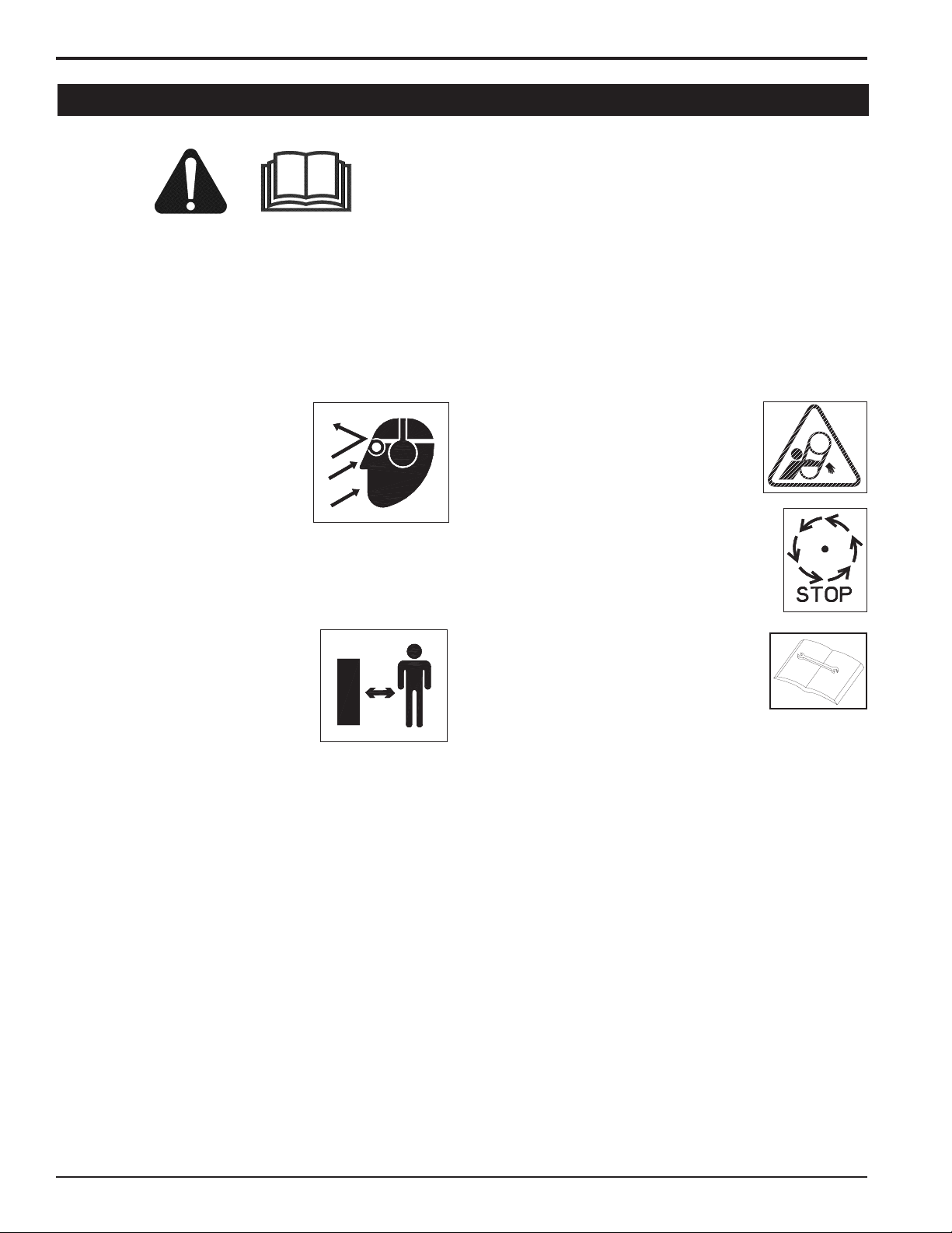
1.3 bEfoRE opERATINg
Read and understand this Owner/Operator's manual. Be
1.
completely familiar with the controls and the proper use of
this equipment.
Familiarize yourself with all of the safety and operating
2.
decals on this equipment and on any of its attachments or
accessories.
keep safety decals clean and legible. Replace missing or
3.
illegible safety decals.
Obtain and wear safety glasses and use hearing protection
4.
at all times when operating this
machine.
Avoid wearing loose fitted clothing.
5.
Never operate this machine wearing clothing with drawstrings that
could wrap around or get caught in
the machine.
Do not operate this machine if you are under the influence
6.
of alcohol, medications, or substances that can affect your
vision, balance or judgement. Do not operate if tired or ill.
You must be in good health to operate this machine safely.
Do not operate this equipment in the vicinity of bystanders.
7.
keep the area of operation clear of all
persons, particularly small children.
It is recommended that bystanders
keep at least 50 feet (15 meters)
away from the area of operation.
Do not allow children to operate this
8.
equipment.
use only in daylight or good artificial light.
9.
Do not run this equipment in an enclosed area. Engine ex-
10.
haust contains carbon monoxide gas, a deadly poison that is
odorless, colorless and tasteless. Do not operate this equipment in or near buildings, windows or air conditioners.
Always use an approved fuel container. Do not remove gas
11.
cap or add fuel when engine is running. Add fuel to a cool
engine only.
Do not fill fuel tank indoors. keep open flames, sparks,
12.
smoking materials and other sources of combustion away
from fuel.
Do not operate machine without shields in place. Failure to
13.
do so may cause serious injury or death.
keep all guards, deflectors, and shields in
14.
good working condition.
Before inspecting or servicing any part of
15.
this machine, shut off the machine, disconnect the battery, remove the ignition key
and make sure all moving parts have come
to a complete stop.
Check that all screws, nuts, bolts, and
16.
other fasteners are secured, tightened
and in proper working condition before
starting the machine and once every 8
hours of operation.
Do not transport or move machine while the machine is
17.
operating or running.
PN 18280-00 R0413064
Page 7
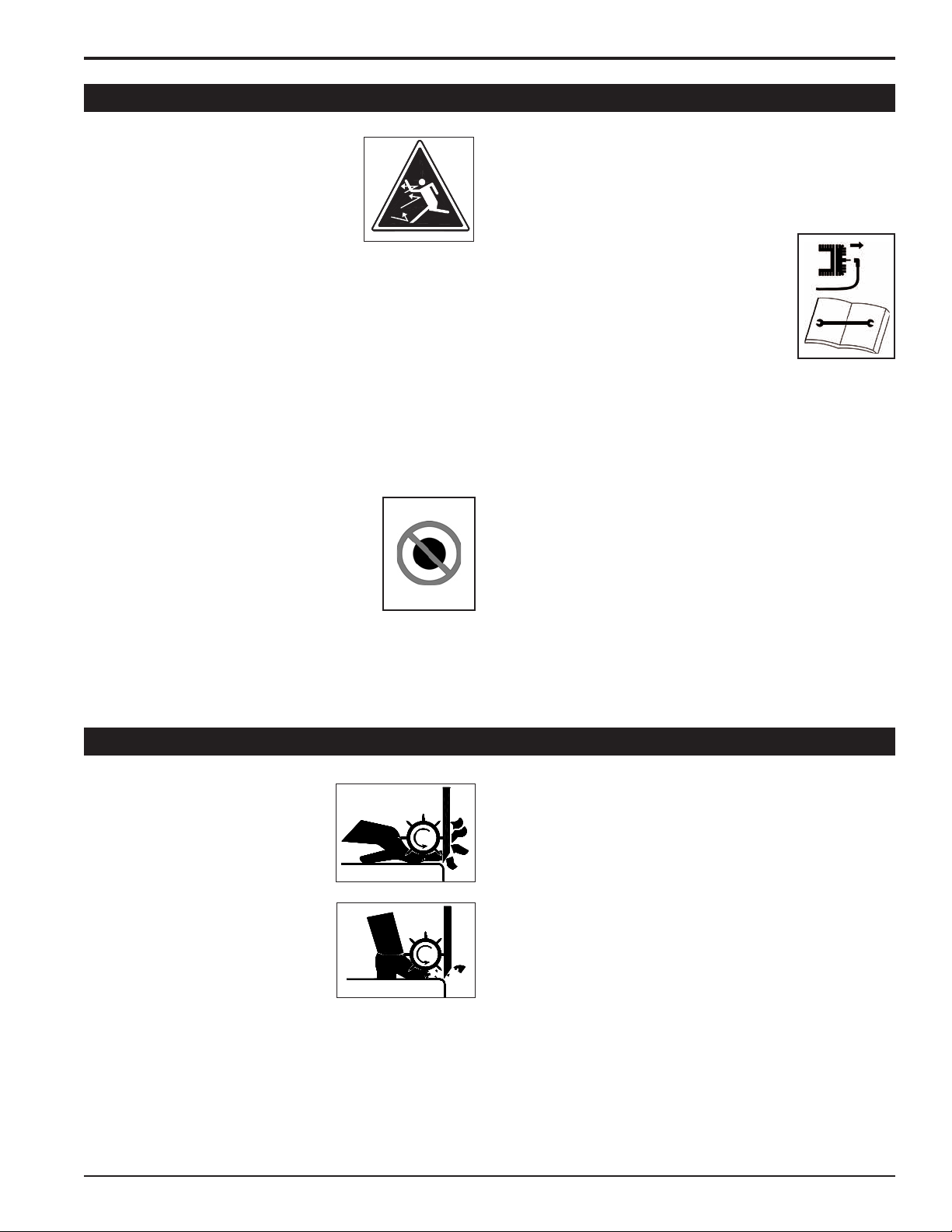
1.4 opERATIoN sAfETY
WRONG
WRONG
SAFETY
1.
Always stand clear of discharge area
when operating this machine. keep face
and body away from feed and discharge
openings.
2.
keep hands and feet out of feed and
discharge openings while machine is operating to avoid serious personal injury.
Stop and allow machine to come to a complete stop before
clearing obstructions.
3.
Set up your work site so you are not endangering traffic and
the public. Take great care to provide adequate warnings.
4.
Do not climb on machine when operating. keep proper
balance and footing at all times.
5.
Check cutting chamber to verify it is empty before starting
the machine.
6.
The disk will continue to rotate when clutch is disengaged.
Shut off the machine, disconnect the battery, remove the
ignition key and make sure all moving parts have come to
a complete stop.
7.
Do not insert branches larger than 8 inches
in diameter into chipper or machine damage
8 INch
may occur.
8.
When feeding material into machine, do
not allow metal, rocks, bottles, cans or any
other foreign material to be fed into the
machine.
9.
Ensure debris does not blow into traffic, parked cars, or
203 mm
pedestrians.
keep the machine clear of debris and other accumula-
10.
tions.
Do not allow processed material to build up in the discharge
11.
area. This may prevent proper discharge and can result in
kickback of material through the feed opening.
Shut off machine immediately if the machine
12.
becomes clogged, the cutting mechanism
strikes any foreign object, or the machine
starts vibrating or making an unusual noise.
Shut off the machine, disconnect the battery, remove the ignition key and make sure
all moving parts have come to a complete
stop. After machine stops:
Inspect for damage.
A.
Replace or repair any damaged parts.
B.
Check for and tighten any loose parts.
C.
On electric start models, disconnect cables from battery
13.
before doing any inspection or service. Remove key.
Check blade bolts for proper torque after every 8 hours of
14.
operation. Check blades and rotate or resharpen daily or as
required to keep blades sharp. Failure to do so may cause
poor performance, damage or personal injury and will void
the machine warranty.
1.5 fEED RoLLER sAfETY
The feed roller can cause serious
1.
injury or death. keep hands, feet
and clothing away from the feed
roller and chipper disk blades.
Never climb onto the feed chute
2.
when the unit is operating or running.
3.
Do not overreach. keep proper
balance and footing at all times.
Never allow passengers to ride on
4.
the feed chute.
PN 18280-00 R041306
When feeding material into the feed roller:
5.
Wear eye, face and hearing protection.
A.
Release material and stand to side of feed chute.
B.
When inspecting or servicing the feed roller, secure the feed
6.
roller in the raised position using the snap pin located on
the roller slide.
5
Page 8
SAFETY
DANGER / POISON
SHIELD EYES
EXPLOSIVE GASES
CAN CAUSE
BLINDNESS OR
INJURY
NO
• SPARKS
• FLAMES
• SMOKING
SULFURIC
ACID
CAN CAUSE
BLINDNESS OR
SEVERE BURNS
FLUSH EYES
IMMEDIATELY
WITH WATER
GET
MEDICAL
HELP
FAST
KEEP OUT OF THE REACH OF CHILDREN. DO NOT TIP. KEEP VENT CAPS TIGHT AND LEVEL.
1.6 MAINTENANcE AND sToRAgE sAfETY
Before inspecting, servicing, storing, or changing an acces-
1.
sory, shut off the machine, disconnect the battery, remove
the ignition key and make sure all moving parts have come
to a complete stop.
Replace any missing or unreadable safety decals. Refer
2.
to the parts manual for part numbers when ordering safety
decals from an authorized dealer.
1.7 ToWINg sAfETY
Rotate the discharge tube to face the opposite direction of
1.
the towing vehicle before towing.
Insert transport safety pin and clip, and set turntable brake
2.
handle to locked position.
Connect hitch safety chains. Tighten and secure trailer hitch
3.
bolts. Do not attempt to tow the trailer if the vehicle is not
equipped with a 2” ball.
Do not exceed maximum towing speed, indicated on tire
4.
sidewall. Inflate tires to manufacturers specifications as
stated on the tire sidewall.
Allow machine to cool before storing in an enclosure.
3.
Store the machine out of reach of children and where fuel
4.
vapors will not reach an open flame or spark.
Never store this machine with fuel in the fuel tank inside a
5.
building where fumes may be ignited by an open flame or
spark. Ignition sources can be hot water and space heaters,
furnaces, clothes dryers, stoves, electric motors, etc.
Optimum towing performance can be achieved by maintain-
5.
ing a horizontal trailer hitch.
Check wheel lug bolts periodically to ensure they are tight
6.
and secure.
Make sure the jack stand and the rear stabilizer on trailer
7.
are in the uP position during towing.
Never allow passengers to ride on the chipper.
8.
If applicable, shut off fuel supply when towing.
9.
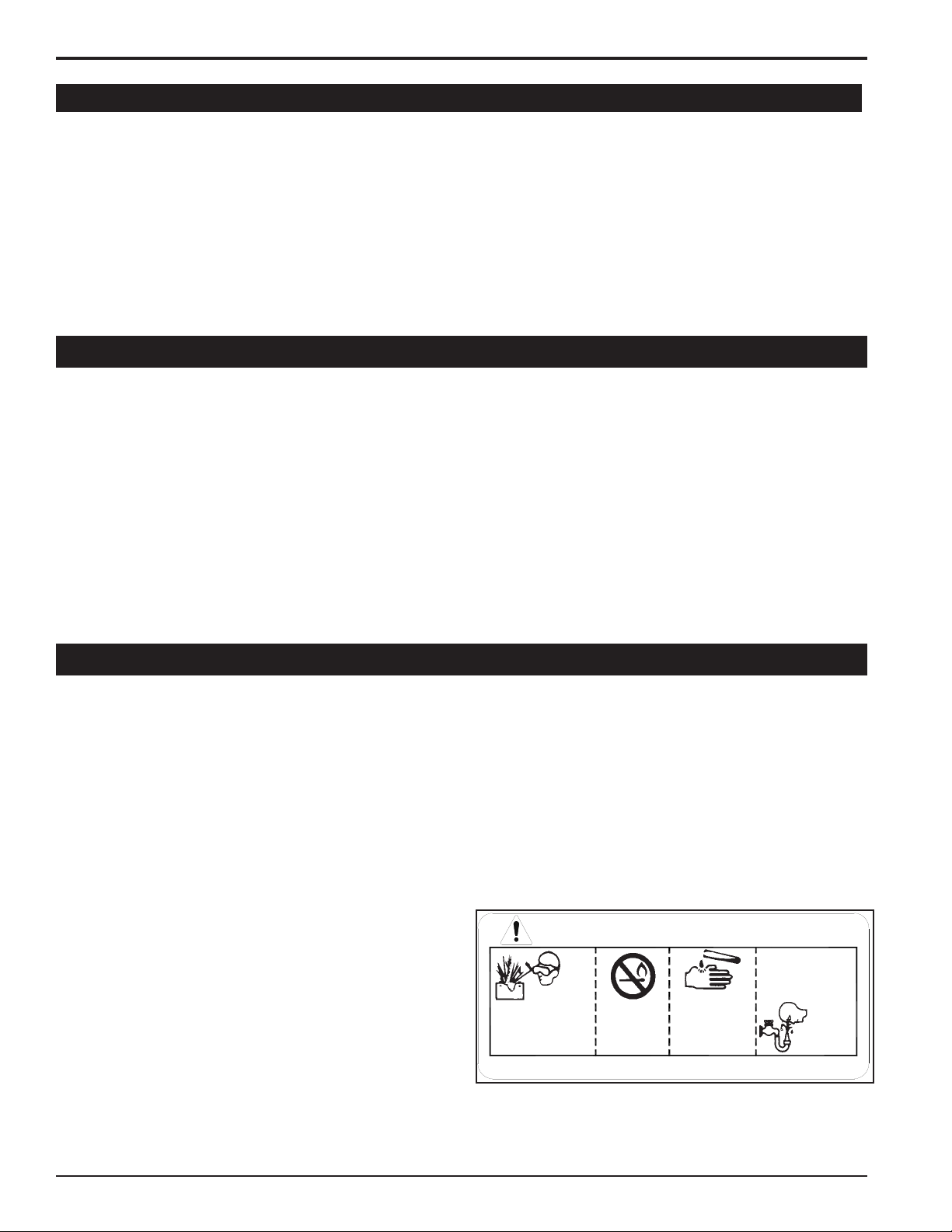
1.8 bATTERY sAfETY
Improper use and care of the battery on electric start models
1.
can result in serious personal injury or property damage.
Always observe the following safety precautions.
Poison/Danger - Causes Severe Burns. The battery contains
2.
sulfuric acid. Avoid contact with skin, eyes or clothing. keep
out of reach of children.
ANTIDOTE-External Contact: Flush immediately with
lots of water.
ANTIDOTE-Internal: Drink large quantities of water
or milk. Follow with milk of magnesia, beaten egg or
vegetable oil. Call a physician immediately.
ANTIDOTE-Eye Contact: Flush with water for 15
minutes. Get prompt medical attention.
The battery produces explosive gases. keep sparks, flame
3.
or cigarettes away. ventilate area when charging battery.
Always wear safety goggles when working near battery.
The battery contains toxic materials. Do not damage bat-
4.
tery case. If case is broken or damaged, avoid contact with
battery contents.
Neutralize acid spills with a baking soda and water solution.
5.
Properly dispose of a damaged or worn-out battery. Check
with local authorities for proper disposal methods.
Do not short circuit battery. Severe fumes and fire can
6.
result.
Before working with electrical wires or components, discon-
7.
nect battery ground (negative) cable first. Disconnect positive cable second. Reverse this order when reconnecting
battery cables.
PN 18280-00 R0413066
Page 9
SAFETY
18606-00
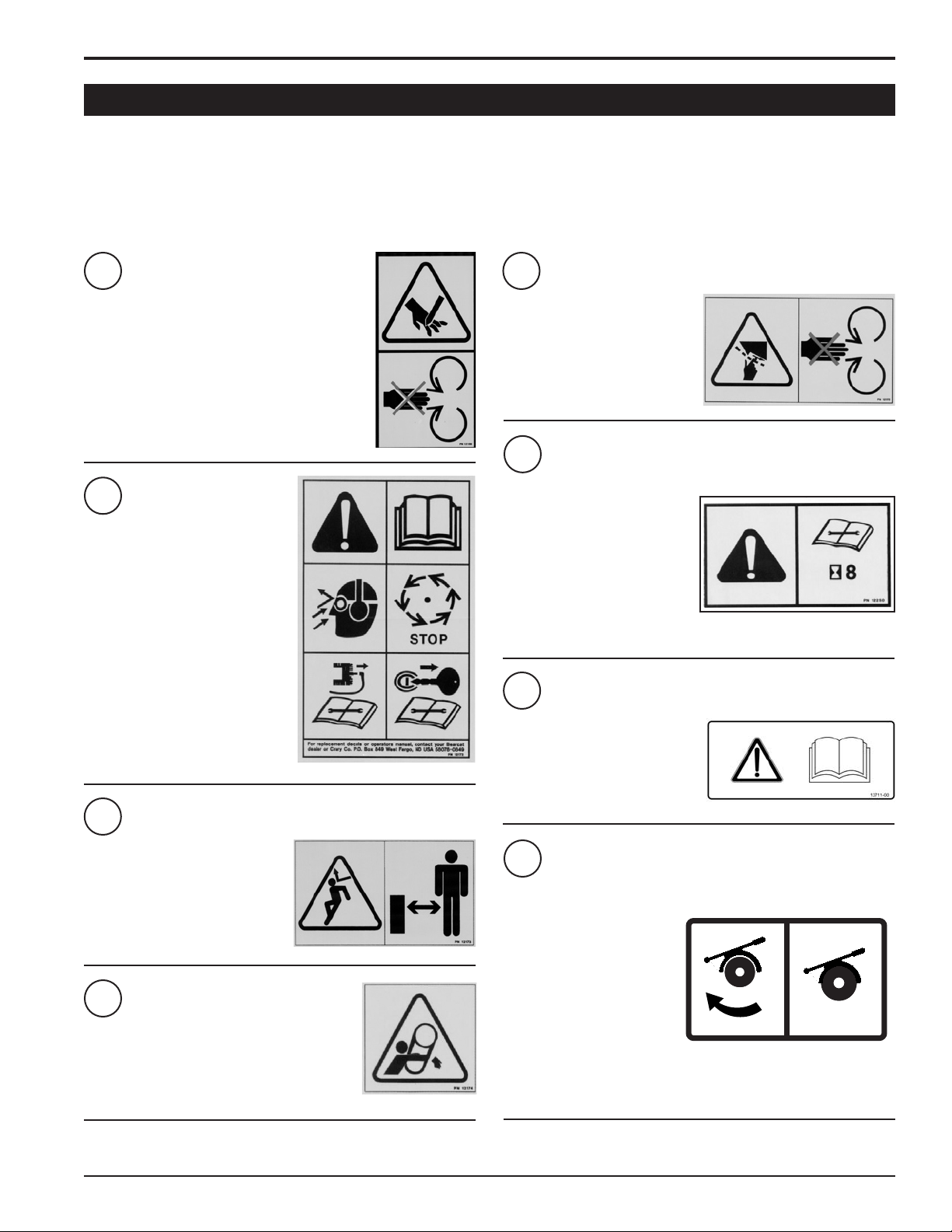
1.9 sAfETY DEcALs
See Section 1.10 for decal locations. Familiarize yourself with all of the safety and operating decals on the machine and the associated hazards. See the engine owners manual or contact the engine manufacturer for engine safety instructions and decals. Make
certain that all safety and operational decals on this machine are kept clean and in good condition. The decals are shown below at
reduced sizes. Refer to the parts catalog if you need a replacement decal. Decals that need replacement must be applied to their
original locations.
PN 12169
1
kEEP hANDS AND FEET OuT OF INLET AND
DISChARGE OPENINGS WhILE MAChINE IS OPERATING TO AvOID SERIOuS PERSONAL INjuRY. STOP
AND ALLOW MAChINE TO COME TO A COMPLETE
STOP BEFORE CLEARING OBSTRuCTIONS.
PN 12172
2
READ AND uNDERSTAND ThIS OWNER/OPERATORS MANuAL. BE COMPLETELY FAMILIAR WITh ThE CONTROLS AND ThE PROPER uSE OF
ThIS EquIPMENT
OBTAIN AND WEAR SAFETY GLASSES AND uSE hEARING PROTECTION
AT ALL TIMES WhEN OPERATING
ThIS MAChINE.
BEFORE INSPECTING OR SERvICING
ANY PART OF ThIS MAChINE, ShuT
OFF POWER SOuRCE, DISCONNECT
SPARk PLuG WIRE FROM SPARk
PLuG AND MAkE SuRE ALL MOvING
PARTS hAvE COME TO A COMPLETE
STOP.
PN 12173
3
PN 12175
5
kEEP hANDS AND FEET OuT OF
INLET AND DISChARGE OPENINGS
WhILE MAChINE IS OPERATING
TO AvOID SERIOuS PERSONAL IN
juRY. STOP AND ALLOW MAChINE
TO COME TO A COMPLETE STOP
BEFORE CLEARING OBSTRuCTIONS.
PN 12250
6
ChECk BLADE BOLTS FOR PROPER TORquE AFTER EvERY 8
hOuRS OF OPERATION. ChECk
BLADES AND ROTATE OR REShARPEN DAILY OR AS REquIRED
TO kEEP BLADES ShARP. RE
FER TO OWNERS MANuAL FOR
INSTRuCTIONS. FAILuRE TO DO
SO MAY CAuSE POOR PERFOR
MANCE, DAMAGE OR PERSONAL
INjuRY AND WILL vOID ThE MA
ChINE WARRANTY.
PN 13711-00
7
READ AND uNDERSTAND ThIS
OWNER/OPERATORS MANuAL.
BE COMPLETELY FAMILIAR
WITh ThE CONTROLS AND ThE
PROPER uSE OF ThIS EquIPMENT.
-
-
-
-
DO NOT OPERATE ThIS EquIPMENT
IN ThE vICINITY OF BYSTANDERS.
DO NOT ALLOW ChILDREN TO OPERATE ThIS EquIPMENT. ALWAYS
STAND CLEAR OF DISChARGE AREA
WhEN OPERATING ThIS MAChINE.
kEEP FACE AND BODY AWAY FROM
DISChARGE AREAS.
PN 12174
4
DO NOT OPERATE MAChINE WIThOuT ShIELDS IN
PLACE. FAILuRE TO DO SO MAY CAuSE SERIOuS
INjuRY OR DEATh.
PN 18280-00 R041306
DO NOT OPERATE ChIPPER
WIThOuT TuRNTABLE BASE
LOCkED IN PLACE. FAILuRE TO
DO SO MAY RESuLT IN DAMAGE
TO MAChINE AND/OR SERIOuS
BODILY INjuRY.
FOR TRANSPORT, RETuRN
ChIPPER TO TRANSPORT PO
SITION, INSERT TRANSPORT
SAFETY PIN AND CLIP, AND SET
TuRNTABLE BRAkE hANDLE
TO LOCkED POSITION. FAILuRE TO DO SO MAY RESuLT IN
DAMAGE TO MAChINE AND/OR
SERIOuS BODILY INjuRY.
8
PN 18606-00
-
7
Page 10
SAFETY
18555-00
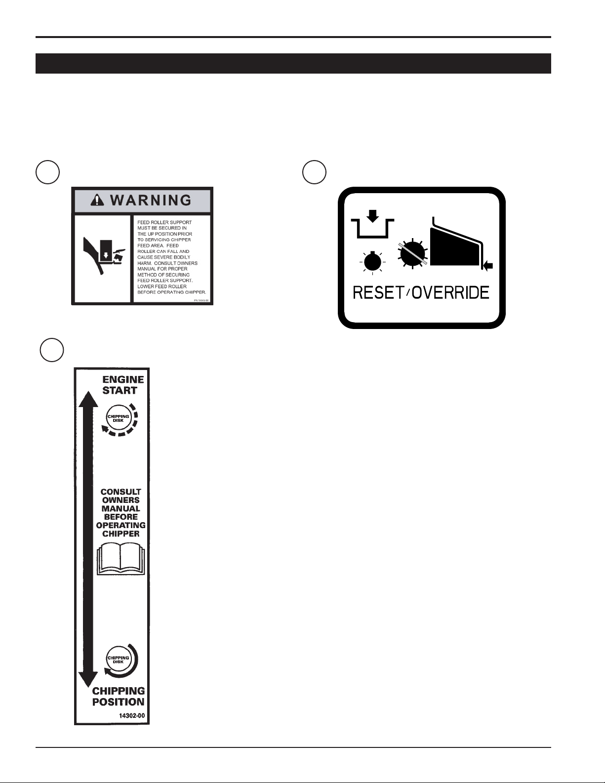
1.9 sAfETY DEcALs (coN'T)
See Section 1.10 for decal locations. Familiarize yourself with all of the safety and operating decals on the machine and the associated hazards. See the engine owners manual or contact the engine manufacturer for engine safety instructions and decals. Make
certain that all safety and operational decals on this machine are kept clean and in good condition. The decals are shown below at
reduced sizes. Refer to the parts catalog if you need a replacement decal. Decals that need replacement must be applied to their
original locations.
9
10
pN 14049-00
pN 14302-00
11
pN 18555-00
PN 18280-00 R0413068
Page 11
SAFETY
3
2
1
6
10
5
8
4
7
9
3
2
1
6
10
11
8
5
4
7
9
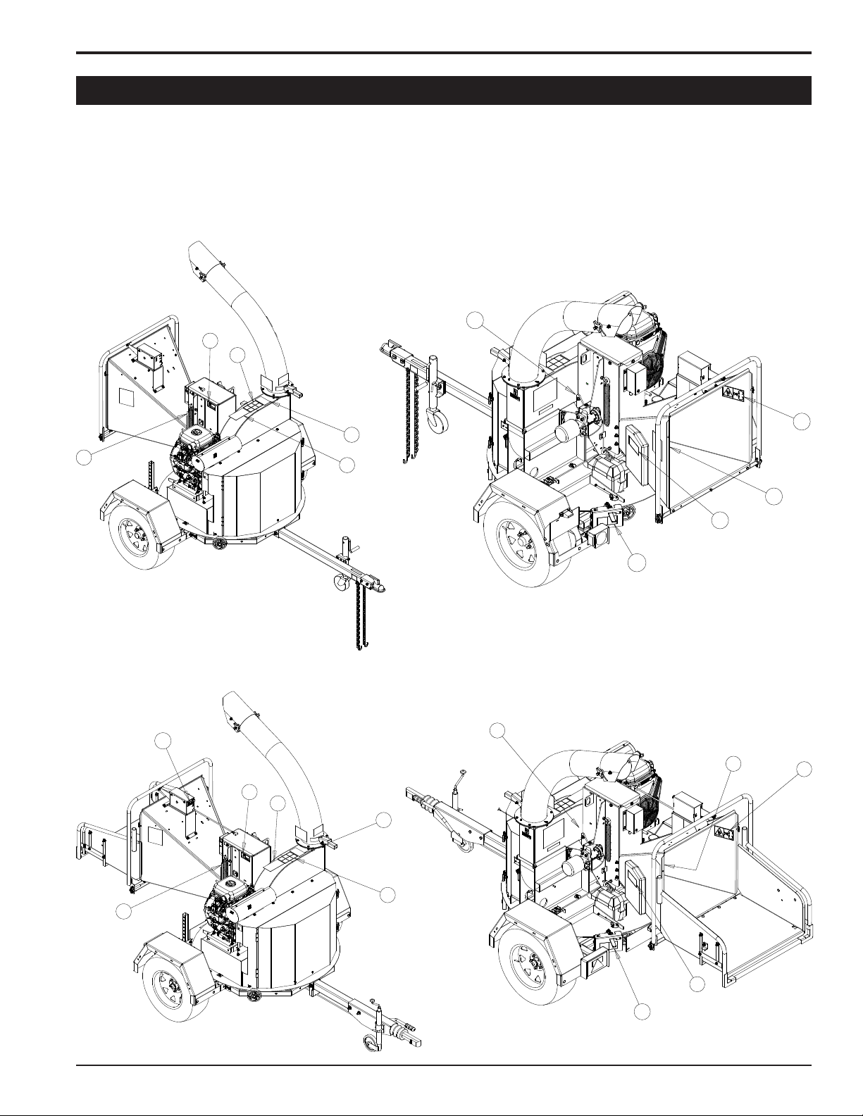
1.10 sAfETY DEcAL LocATIoNs
The numbers below correspond to the decals in Section 1.9. Familiarize yourself with all of the safety and operational decals on the
machine and the associated hazards. See the engine owners manual or contact the engine manufacturer for engine safety instructions and decals. Make certain that all safety and operating decals on this machine are kept clean and in good condition. The decals
are shown below at reduced sizes. Refer to the parts catalog if you need a replacement decal. Decals that need replacement must
be applied to their original locations.
Models 76824, 76835
Models 76824S, 76835S
PN 18280-00 R041306
9
Page 12

2
Section
AssEMbLY
WARNINg
Before inspecting or servicing any part of this machine, shut
off power source, disengage the hydraulics, remove ignition key and make sure all moving parts have come to a
complete stop.
2.1 TIREs AND RIMs (DoMEsTIc AND s MoDELs oNLY)
Mount tires and rims to the axle using the lug nuts.
1.
Attach the fender supports to the trailer using three 1/2" x 3-1/2" hex bolts, washers & nuts.
2.
Attach the fenders to the fender supports using four 3/8" x 1" carriage bolts, washers and nuts.
3.
2.2 TRAILER hITch (DoMEsTIc AND s MoDELs oNLY)
S & F-MODELS:
Thread the wire harness through the hitch tube and slide
1.
the hitch tube into the trailer frame. Secure using two 1/2" x
4-1/2" bolts, washers and nuts (provided in owner's kit).
Slide the hitch coupler onto the hitch tube from the top and
2.
secure using 1/2" bolts, nuts and washers.
Thread the wire harness through the metal loop on the un-
3.
derside of the coupler.
If any bolts or nuts are dropped in the machine, be sure to
remove them before starting the machine. Remove items
from the shredder area by removing the discharge screen.
DOMESTIC MODELS:
Thread the wire harness through the hitch tube and slide the
hitch into the trailer frame. Secure using two 1/2" x 4-1/2" bolts,
washers and nuts (provided in owner's kit).
IMpoRTANT
2.3 REAR sTAbILIzER
verify that the rear stabilizer is installed. To install the rear stabilizer, slide the stabilizer into the corresponding bracket beneath the
rear of the chipper frame. Adjust the stabilizer and secure with the provided snap pin.
2.4 chEckINg/ADDINg MoToR oIL To ENgINE
Check the oil level and, if needed, ll the engine crankcase with the type and amount of oil specied in the engine owner's manual.
PN 18280-00 R04130610
Page 13

2.5 chEckINg/ADDINg hYDRAuLIc fLuID
ASSEMBLY
Hydraulic uid drives the feed roller. The hydraulic pump is direct or belt driven from the engine or disk rotor.
The hydraulic pump requires premium hydraulic uids containing high quality rust, oxidation, and foam inhibitors. These include premium turbine oils, API CD engine oils per SAE j183,
M2C33F or G automatic transmission uids meeting Allison C-3
or Caterpillar TO-2, and certain specialty agricultural tractor u-
ids.
If system has no oil, follow this startup procedure:
Clean all system components (reservoir, fittings, etc.) before
1.
starting the hydraulic pump.
After filtering the hydraulic fluid, fill the hydraulic reservoir.
2.
2.6 fILLINg ThE TANk
DANgER
Fuel is highly ammable and its vapors are explosive. To prevent personal injury or property
damage:
Store fuel only in approved containers, in well
ventilated, unoccupied buildings, away from
sparks or ames. Do not ll the fuel tank while the engine
is hot or running. Spilled fuel could ignite if it comes in
contact with hot parts or sparks from ignition. Do not start
the engine near spilled fuel. Never use fuel as a cleaning
agent.
Fill the inlet line leading from the reservoir to the pump before
3.
start-up. Loosen the fitting at the pump on this inlet line until
oil bleeds out.
Start the engine and run at the lowest possible RPM.
4.
As you purge air from the unit, the oil level in the reservoir
5.
will drop and bubbles may appear in the fluid. Refill the
reservoir as necessary.
Run the feed roller in both directions for several minutes until
6.
any remaining air purges from the unit. Refill the reservoir
as necessary.
Shut down the engine, check for and correct any fluid leaks,
7.
and check the reservoir level. Add fluid if necessary. The
hydraulic pump is now ready for operation.
For best results use only clean, fresh, fuel. Purchase fuel in
small quantities and store in clean, approved containers.
REFER TO ThE ENGINE OWNERS MANuAL FOR FuRThER
FILLING INSTRuCTIONS.
IMpoRTANT
Do not attempt to start the engine at this time. Wait until
you have read the complete starting instructions in the Operation Section of this manual.
2.7 coNNEcTINg ThE bATTERY
The machine may or may not have been shipped with a battery
depending on your area. If you did not receive a battery with
your machine, you will need to purchase one.
Use a battery that meets or exceeds the following specications:
Battery Category, Lawn and Garden
BCI Group Size U1
200-250 ccA
7-3/4" X 5-3/16" X 7-5/16"
Suggested Source:
Exide Cutting Edge, Type GT-H
After purchasing your battery, ll, charge and install the battery
according to the battery owners manual.
PN 18280-00 R041306
WARNINg
To avoid sparks and a possible explosion or re due to a
short circuit, do not touch the positive (+) battery terminal
and any surrounding metal with tools, jewelry or other metal
objects. When installing battery cables, connect the posi-
tive (+) cable rst and the negative (-) cable last.
IMpoRTANT
Do not attempt to start the engine at this time. Wait until
you have read the complete starting instructions in the Operation Section of this manual.
11
Page 14

ASSEMBLY
CHIPPER CHUTE
HYDRAULIC FEED
2.8 chIppER chuTE
WARNINg
Do not operate this unit without the chipper chute correctly
installed. Rotating cutting blades can cause serious personal injury.
Mount the chipper chute to the chipper housing using eight 3/8"
x 1" bolts and locknuts. use three bolts on each side and two on
the bottom (Figure 2.1).
To insert the top bolts, rotate the feed roller until the notches
(one on each side) on the feed roller are aligned with the top
bolt holes.
Figure 2.1 - Chipper Chute Assembly
2.9 chuTE EXTENsIoN TRAY
The Chute Extension Tray is an optional item and purchased
separately for domestic models.
The Chute Extension Tray is standard on S & F models.
After mounting the chipper chute to the chipper housing,
1.
slide the chute extension tray over the chipper chute as
shown in Figure 2.2.
NoTE
Make sure that you position the lip on the extension tray behind the lip on the chipper chute. This provides a atter surface and prevents obstructions while feeding the machine.
Align the five bolt holes in the chute extension tray with the
2.
bolt holes in the extension hinge.
Insert a 3/8" x 1" carriage bolt (included in owner's kit) through
3.
the two outside holes on the extension tray and the extension
hinge. Secure the bolts with washers and nuts.
Insert one 3/8" x 1" carriage bolt through the end of the chute
4.
support and middle holes on the extension hinge and extension tray. Secure the bolts with washer and nuts. Secure
hairpin Clip
C h i p p e r
Chute
Ext e ns ion
Tray
Position this lip
behind the lip
on the chipper
chute shown
below. hold the
extension tray
directly above
the chipper
chute and slide
it downward.
Feed Control
Lever
Ext e ns ion
hinge
Figure 2.2 - Chute Extension Tray Assembly.
PN 18280-00 R04130612
Page 15

2.10 DIschARgE TubE
SECOND HALF
OF CLAMP.
ZERK
Attach the discharge tube to the mounting flange on the chip-
1.
per frame. half of the mounting clamp is already attached
to the tube. Slide the tube onto the flange and tighten the
bolts to secure it.
Install the second half of the clamp to the tube and flange.
2.
Grease the zerk and tighten the nuts completely.
3.
Loosen each nut one turn and attempt to rotate the tube.
4.
If it does not rotate freely, loosen each nut 1/2 turn until it
rotates freely.
Rotate the tube 360 degrees and lock it in place with the
5.
handle to make sure it is mounted correctly.
NoTE
keep nuts as tight as possible while allowing the discharge
tube to freely turn.
ASSEMBLY
2.11 sWITch boX
coNNEcTINg ThE sWITch boX
Connect the Relay Input plugs to the Proximity Sensors.
1.
Relay Input Plug (Forward): Red/Green/White wires.
•
Relay Input Plug (Reverse): Red/Orange/White wires.
•
Forward/Reverse Sensors: Blue/Black/Brown wires.
•
The forward/reverse sensors have the same color wires.
1.
use the steps below to verify that they are properly connected to the Relay Input Plugs:
Start engine.
•
Move the Control Bar to the REvERSE position.
•
If the feed roller does not rotate in reverse direction,
•
shut off engine and switch the forward & reverse
signal plugs.
The remaining connectors can be connected by matching
2.
the colored wires.
Figure 2.3 - Discharge Tube Assembly
Figure 2.4- Switch Box Connectors.
sETTINg ThE sWITch boX sENsoRs opERATINg
DIsTANcE
Remove the switch box cover.
1.
verify that the sensors are within 2mm (5/64") from the
2.
switch box plate and adjust if needed.
PN 18280-00 R041306
Figure 2.5- Switch Box Sensors.
13
Page 16

3
TURNTABLE
BRAKE
HITCH JACK
(S & F MODELS)
CHUTE EXTENSION TRAY
(S & F MODELS)
FEED ROLLER
CONTROL BAR
ENGINE THROTTLE
COUPLER (51 mm)
(S & F MODELS)
HITCH - DOMESTIC MODELS
COUPLER (2")
HITCH JACK
SAFETY CHAINS
FEED ROLLER
SPEED CONTROL
PARK BRAKE
(S & F MODELS)
SAFETY BAR
TRANSPORT
SAFETY
PIN
DISCHARGE TUBE
DISCHARGE CAP
ENGAGEMENT HANDLE
FEED ROLLER
LIFT JACK
REAR STABILIZER
FEED CHUTE
SWITCH BOX
FEED ROLLER SNAP PIN
fEATuREs & coNTRoLs
Section
understanding how your machine works will help you achieve the best results when using your chipper. The following descriptions
dene the features and controls of your machine.
REfER To ENgINE oWNERs MANuAL foR fuRThER ENgINE opERATINg INsTRucTIoNs.
Figure 3.1 - Features & Controls
PN 18280-00 R04130614
Page 17

FEATURES & CONTROLS
3.1 ENgINE ThRoTTLE
This controls the speed of the engine. Increase the throttle by
moving the switch to the FAST position. To decrease the throttle, move the switch to the SLOW position.
3.2 ENgAgEMENT hANDLE
During engine start-up, the engagement handle must be in
the disengaged (uP) position. With the engine at 1/4 throttle,
carefully engage the disk by slowly pushing the engagement
handle down, allowing the disk to speed up gradually. Engaging the chipper too quickly with the engine at full or half throttle
will bog down the engine and will shorten the life of the belt. To
disengage the disk, rst idle the engine down and then pull the
engagement handle up.
3.3 TuRNTAbLE bRAkE
Locks the turntable to the frame for any chipping position
(0°-360°). The chipper base must always be locked in place.
Failure to do so may result in machine vibration, serious bodily
injury or death.
3.7 chuTE EXTENsIoN TRAY
s & f MoDELs oNLY
that folds down. Around the edge of the tray is an orange control
arm that will contact a safety switch (inside the switch box) when
depressed. The safety switch will stop the hydraulic ow to the
feed roller. The chipper will not feed material until the reset button on the top of the feed chute is pressed. The switch box has
a red light that will indicate the switch has been triggered and
will not go out until the reset button has been reset. The feed
roller will resume rotation once the machine has been reset.
: The feed chute has an extension tray
3.8 fEED RoLLER LIfT jAck
used to lift the feed roller. The feed roller can be raised to
inspect and service the machine and to clear a plugged disk.
Secure the feed roller in the raised position using the provided
snap pin.
3.9 fEED RoLLER coNTRoL bAR
To engage the feed roller move the control bar. The cycle of
the control bar, front to back, is REvERSE (R), FORWARD (F),
STOP, REvERSE (R).
3.4 DIschARgE TubE
Directs the discharge of chipped material horizontally. The discharge tube can be rotated 360° horizontally by pressing down
on the lock lever and rotating the discharge tube until the discharge deector faces the desired position. Release the discharge lock lever and slightly rotate the discharge tube until the
lock pin snaps into place in one of the holes on the base of the
discharge tube.
3.5 DIschARgE cAp
Directs the discharge of material vertically. Adjust the discharge
cap by turning the knob located on the side. Turn knob counterclockwise to loosen discharge cap. Adjust to desired position.
Turn knob clockwise to secure discharge cap.
3.6 fEED chuTE
Materials to be chipped are fed into the feed chute, through the
feed roller, to the chipper blades.
3.10 fEED RoLLER spEED coNTRoL
Controls the speed of the feed roller. Allows the operator to
have better control over the material being fed into the chipper. Turning the knob clockwise will decrease the speed of the
feed roller. Turning the knob counterclockwise will increase the
speed of the feed roller.
3.11 hITch jAck
used to adjust the height of the hitch. Always have in uP position and clear from ground when moving. When in use, place in
DOWN position on a level surface.
3.12 sAfETY chAINs
Safety chains are used, during towing, to prevent the chipper
from completely separating from the tow vehicle in the event the
chipper detaches from the tow vehicle. Cross the safety chains
under the hitch and connect to tow vehicle.
3.13 REAR sTAbILIzER
PN 18280-00 R041306
Prevents the chipper from tipping when disconnected from tow
vehicle. Always have in uP position and clear from ground
when moving. When in use, place in DOWN position on a level
surface.
15
Page 18

4
opERATIoN
Section
As with any other piece of outdoor power equipment, getting
the feel for how your machine operates and getting to know the
best techniques for particular jobs are important to overall good
performance.
chIppINg opERATIoN
The chipping operation takes place on the front of the machine,
where hardened steel chipper blades are mounted on a rotating
disk assembly. Material fed into the chipper chute is sliced into
small chips and propelled out through a discharge tube.
4.1 sTARTINg ThE MAchINE
Before starting, fill engine with oil to the correct level (see en-
1.
gine manual for operation and maintenance instructions).
Fill fuel tank with unleaded regular gasoline. DO NOT MIX
2.
OIL WITh GASOLINE.
Check hydraulic fluid level and fill to correct level if neces-
3.
sary.
Move engagement handle upward to disengage drive belts
4.
Start the engine (see engine owners manual).
5.
WARNINg
Before operating your machine, be sure you read and understand all safety, controls and operating instructions in this
Owner/Operator's manual and on your machine. Failure to
follow these instructions can result in serious injury or property damage.
Once engine is running and no choke is needed, set engine
6.
to 1/4 throttle and slowly release the engagement handle.
This will engage the drive belt and the disk will turn.
If the engine stalls when engaging the drive belt, either use
7.
more choke or increase engine RPM.
Bring engine to full RPM.
8.
NoTE
4.2 sToppINg ThE MAchINE
Move throttle to SLOW position.
1.
Move engagement handle upward to disengage drive belt.
2.
Shut off engine (see engine owners manual).
3.
Allow machine to come to a complete stop.
4.
4.3 RoTATE chIppER bAsE
Disengage turntable brake.
1.
Rotate the turntable to desired position.
2.
Once the turntable has been properly positioned, engage
3.
brake.
It is important to bring the engine to full RPM before operating the chipper. The chipper feed controller requires the
chipper disk to turn at full RPM in order to operate.
NoTE
The disk will continue to turn for some time after the engine
has been shut off. Make sure disk has stopped completely
before inspecting or servicing machine.
WARNINg
The chipper base must always be locked in place. Failure to
do so may result in machine vibration, serious bodily injury
or death.
PN 18280-00 R04130616
Page 19

4.4 DIREcTINg ThE DIschARgE TubE
The discharge tube can rotate 360° and lock into different positions using the discharge lock lever. The discharge cap directs
how high and how far the chipped material blows.
Adjust the discharge tube by pressing down on the lock lever
and rotating the discharge tube until the discharge deector
faces the desired position. Release the discharge lock lever and
slightly rotate the discharge tube until the lock pin snaps into
place in one of the holes on the base of the discharge tube (Figure 4.1).
Adjust the discharge cap by turning the knob located on the side.
Turn knob counterclockwise to loosen discharge cap. Adjust to
desired position. Turn knob clockwise to secure discharge cap.
4.5 RAIsE/LoWER ThE AccEss covER
OPERATION
Figure 4.1 - Directing the Discharge Tube/Cap.
Rotate the discharge chute so it is parallel to the access cover.
1.
Remove the two 3/8" x 1-1/4" bolts, nuts and washers securing the access cover to the chipper housing.
2.
After lowering the access cover, secure the access cover to the chipper housing using two 3/8" x 1-14" bolts, nuts and wash-
3.
ers.
4.6 fEED RoLLER spEED coNTRoL
The feed roller speed control is used to control the speed of the
feed roller allowing the operator to have better control of material being fed into the chipper.
For optimum chipping, it is recommended that the feed roller
operate at a faster rate for smaller branches and at a slower rate
for larger branches.
Figure 4.2 - Feed Roller Speed Control.
PN 18280-00 R041306
17
Page 20

OPERATION
SAFETY BAR
(S & F MODELS)
RESET/OVERRIDE
BUTTON
(S & F MODELS)
SAFETY BAR
ACTIVATED
(S & F MODELS)
R
REVERSE
R
F
FORWARD
STOP
REVERSE
CONTROL BAR
4.7 chIppER fEED coNTRoLLER
The chipper is equipped with a pre-programmed feed controller.
The controller is located on the chipper housing above the chipper chute. The controller serves a variety of functions including monitoring chipper disk RPM, controlling the feed roller, and
providing routine maintenance alerts. The control bar located on
the feed chute will control the feed roller.
The controller functions are further detailed below:
The controller operates the feed roller. The controller moni-
1.
tors the RPMs of the chipper disk and won't operate until
the engine is at full RPM. If the chipper disk drops below
the normal operating RPM, the feed roller stops. When the
chipper disk returns to the normal operating RPM, the feed
roller will reengage.
NoTE
It is important to bring the engine to full RPM before operating the chipper. The chipper feed controller requires the
chipper disk to turn at full RPM in order to operate.
The controller also has a “try again” feature. The controller
2.
monitors the hydraulic pressure of the feed roller. If it senses
the level is too high (the feed roller becomes obstructed) the
controller will reverse the feed roller , removing the material
trying to be chipped. The controller will then engage the roller
into the forward position and try to feed the material again. If
this cycle continues, remove the obstruction manually. Trim
or reposition material if necessary.
The feed controller is programmed to display the following
3.
text messages:
15 hour Service Code
•
•
100 hour Service Code
Normal Operating RPM: "Feed control system
•
: "Change/Service blades".
: "Change engine oil".
available".
high Pressure
•
Feed Roller Stop Switch: "Forward feed stopped".
•
: "Try again feature activiated".
- Domestic Models: Disk RPM too low.
- S & F Models: Disk RPM too Low or Safety
Bar Activated.
SAFETY BAR: S & F models only. If safety bar has been
4.
activated the red LED will light up. Push the reset/override
button to resume forward feed (Figure 4.3).
To overcome false trips of the safety bar by material
4.
being chipped, the reset/override button may be held in for
5 seconds. To repeat, release button and hold in again.
NOTE: The RPM sensor on the disk must ash or the controller
won’t work. Clearance between the sensor and the bolt must be
between 1/32” and 3/32”.
4.8 fEED RoLLER coNTRoL bAR
The feed roller control bar is used to manually control the rotation of the feed roller.
FORWARD (F) rotation is used to move material into the feed
chute towards the chipper blades.
REvERSE (R) rotation is used to push material out of the feed
chute away from the chipper blades.
STOP is used to halt the rotation of the feed roller.
opERATINg
1.
2.
3.
4.
5.
Start the chipper engine. Bring the machine to 1/4 operating
speed (Section 4.1).
Slowly release engagement handle to engage the drive
belt.
Bring the machine to full throttle.
Engage the hydraulic feed by moving the control bar as
shown in Figure 4.3.
If the chipper jams, reverse the feed by moving the control
bar to the reverse position. Remove the branch and rotate
it before reinserting into the chute again.
Figure 4.3 - Control Arm Operation
PN 18280-00 R04130618
Page 21

4.9 ToWINg
OPERATION
S & F MODELS:
hookINg
Rotate the discharge tube to face the opposite direction of
1.
the towing vehicle before towing.
Insert transport safety pin and clip, and set turntable brake
2.
handle to locked position.
Raise rear stabilizer.
3.
Open the coupler latch.
4.
Raise the trailer hitch until the coupler is above the height of
5.
the hitch ball (51 mm hitch ball) on the towing vehicle.
Align the coupler over the hitch ball and lower the trailer hitch
6.
until the coupler fully engages the hitch ball.
Close the coupler latch securing the coupler to the hitch
7.
ball.
Connect the wire harness into the tow vehicle.
8.
Raise the jack stand and secure to the hitch.
9.
uNhookINg
Disconnect the wire harness from the tow vehicle.
1.
unlatch the coupler and disconnect the hitch coupler from
2.
the hitch ball.
Move the hitch of the chipper away from the hitch ball, lower
3.
the jack stand and secure.
Lower rear stabilizer.
4.
NoTE
Optimum towing performance can be achieved by maintaining a horizontal trailer hitch.
DOMESTIC MODELS:
hookINg
Rotate the discharge tube to face the opposite direction of
1.
the towing vehicle before towing.
Insert transport safety pin and clip, and set turntable brake
2.
handle to locked position.
Raise rear stabilizer.
3.
Open the coupler latch.
4.
Raise the trailer hitch until the coupler is above the height of
5.
the hitch ball (2" hitch ball) on the towing vehicle.
Align the coupler over the hitch ball and lower the trailer hitch
6.
until the coupler fully engages the hitch ball.
Close the coupler latch securing the coupler to the hitch
7.
ball.
Install the hitch pin through the coupler latch.
8.
Cross the safety chains under the hitch and connect to tow-
9.
ing vehicle.
Connect the wire harness to the tow vehicle.
10.
Raise the jack stand and secure to the hitch using a hitch
11.
pin.
UNHOOKING:
unhook the safety chains from the towing vehicle. Latch
1.
safety chains to the hitch to prevent them from interfering
with chipping.
Disconnect the wire harness from tow vehicle.
2.
Remove the hitch pin from the coupler latch.
3.
unlatch the coupler and disconnect the hitch coupler from
4.
the hitch ball.
Move the hitch of the chipper away from the hitch ball and
5.
lower the jack stand. Secure with a hitch pin.
Lower rear stabilizer.
6.
PN 18280-00 R041306
WARNINg
Return chipper to transport position, insert transport safety
pin and clip, and set turntable brake handle to locked position. Failure to do so may result in damage to the machine
and/or serious bodily injury.
19
Page 22

OPERATION
4.10 chIppINg guIDE
The chipper chips a variety of materials into a more readily decomposed or handled condition. The following guidelines can
help you get started.
Run unit at full operating speed before starting to chip
1.
material.
These machines are most effective when chipping material
2.
0-6" in diameter. Although this machine will accept material up to 8", you may see a reduction in performance when
feeding material larger than 6".
Trim side branches that cannot be bent enough to feed into
3.
the chipper chute. hold small diameter branches together
in a bundle and feed in simultaneously.
Exclude pieces of metal, rocks, bottles, cans, and other
4.
foreign objects when feeding chipable material into the
machine.
Feed brush from the side of the chipper chute, rather than
5.
from the front. Step aside to avoid being hit by the brush
moving into the chipper.
Do not lean over the chipper chute to push objects into the
6.
cutting device. use a push stick or brush paddle.
7.
Never use shovels or forks to feed brush. They can be
chipped, are expensive to replace, and cause extensive
damage. In addition, metal pieces can be ejected from the
chipper chute and cause serious injury or death.
Never feed brush into the chipper chute with your feet.
8.
Place limb, butt end first, into the chipper chute until it con-
9.
tacts the chipper blades. The actual feed rate of the limb
into the chipper will depend on the type of material fed and
sharpness of the cutting blades.
Stop the material feeding and allow the engine to recover if
10.
the engine slows to where it may stall.
Remove the branch and rotate it before reinserting it into the
11.
chute if the chipper jams.
Alternately insert and retract the limb or insert continuously
12.
at a rate that will not kill the engine.
Chipping dead, dry material will create heat and dull the
13.
chipping blades quickly.
Alternate green material with dry material to lubricate the
14.
chipping blades for longer life and better performance.
The chipping blades will become dull and will require periodic
15.
sharpening. Refer to the Service and Maintenance section
for sharpening instructions.
PN 18280-00 R04130620
Page 23

5
sERvIcE & MAINTENANcE
Section
5.1 MAINTENANcE schEDuLE
The items listed in the service and maintenance schedule are to be checked, and if necessary, corrective action taken. This schedule is designed for units operating under normal conditions. If the unit is operating in adverse or severe usage conditions it may be
necessary for the items to be checked and serviced more frequently.
sEE ENgINE oWNERs MANuAL foR fuRThER ENgINE MAINTENANcE AND TRoubLEshooTINg INfoRMATIoN.
sERvIcE AND MAINTENANcE schEDuLE
fREQuENcY
COMPONENT
ENGINE OIL ChECk/FILL
hYDRAuLIC OIL ChECk/FILL
FuEL TANk ChECk/FILL
BATTERY
CONNECTIONS
NuTS & BOLTS ChECk
ChIPPER BLADES
BELT/PuLLEY
ALIGNMENT
DRIvE BELT ChECk
hYDRAuLIC
DRIvE BELT
TIRE PRESSuRE ChECk
ENTIRE MAChINE CLEAN
ENGINE OIL ChANGE
DISChARGE TuBE GREASE
DISk BEARING GREASE
COOLING ShROuDS CLEAN
PRE-CLEANER
ELEMENT
AIR INTAkE CLEAN
hYDRAuLIC OIL FILTER REPLACE
AIR CLEANER ChECk & CLEAN
OIL FILTER
CARTRIDGE
FuEL FILTER
CARTRIDGE
STARTER DRIvE SERvICE
AIR CLEANER REPLACE
* Disk bearing located on the engine side of chipper housing.
** Disk bearing located on the hydraulic side of chipper housing.
1
Perform more frequently in dusty, dirty or severe usage conditions.
2
have a your engine service dealer perform this service.
3
It is a good sign that your chipper blades need sharpening when material stops self feeding.
4
Perform after the rst 50 hours of operation.
5
Refer to engine owners manual for additional maintenance schedules.
MAINTENANCE
REquIRED
ChECk
ChECk, ShARPEN
IF NEEDED
ChECk
ChECk
CLEAN
REPLACE
REPLACE
3
1, 4, 5
1
1
1
4
4
2
BEFORE
EACh
uSE
1
EvERY
8
hRS
EvERY
25
hRS
EvERY
50
hRS
EvERY
100
hRS
* **
EvERY
200
hRS
EvERY
250
hRS
EvERY
500
hRS
EvERY
1
YEAR
PN 18280-00 R041306
21
Page 24

SERVICE & MAINTENANCE
1/8"
1/4"
DISK ASSEMBLY
DISK LOCK HOLE
SHAFT CAP
MATCHING HOLE
ON DISK JACK SHAFT
WARNINg
DISENGAGE ThE hYDRAuLICS, OPEN ShIELD AND MAkE SuRE ALL MOvING PARTS hAvE COME TO A COMPLETE STOP.
BEFORE INSPECTING OR SERvICING ANY PART OF ThIS MAChINE, ShuT OFF POWER SOuRCE,
5.2 DIsk Lock
WARNINg
The disk assembly has a lock mechanism. When working on
the disk assembly, use the lock mechanism at all times.
Follow the steps below to install the disk lock:
There is a hole in the shaft cap, the disk jack shaft and a
1.
matching hole in the bracket mounted to the disk bearing
front side.
Rotate the disk assembly until the hole on the disk jack shaft
2.
lines up with the holes in the disk shaft cap and bracket.
Install a punch or screwdriver into the disk shaft cap, bracket
3.
and shaft.
Remove punch or screwdriver when service and/or mainte-
4.
nance is completed.
5.3 chIppER bLADEs
WARNINg
Chipping blades are sharp! use caution when working on
machine to avoid injury.
The chipper blades will eventually become dull, making chipping
difcult and adding extra strain on the machine. Poor chipping
performance is usually a result of dull chipping blades. It is recommended that the blades be sharpened every 5 - 15 hours or
if your chipper’s performance has decreased. Check for the following symptoms and sharpen the blades if needed.
Severe vibration when feeding material into the chipper.
1.
Small diameter branches do not self-feed.
2.
Chips discharge unevenly or have stringy tails, especially
3.
when chipping green branches.
Before you sharpen the chipping blades, check for permanent
damage. Replace the blade if:
There are cracks, broken corners or nicks greater than 1/8"
1.
(Figure 5.2).
The base of the cutting edge is worn or has been re-sharp-
2.
ened so that the edge extends less than 1/16" above the
disk chipping slot.
Figure 5.1 - Disk Lock
Figure 5.2 - Causes for Replacement
5.3.1 REMovINg ThE bLADEs
Remove the two 3/8 inch retaining bolts securing the access
1.
cover to the main frame assembly.
Tilt access cover over to allow access to disk. Rotate the disk
2.
so that the bolts holding the chipper blades are accessible.
Install the disk lock (Section 5.2). The disk is now restrained
3.
for removing the blades. To access the remaining blades,
remove the punch or screwdriver and reposition disk. Return
the punch or screwdriver to the disk lock hole.
Remove the security lock nuts (on back side of chipper disk)
4.
and the flat head screws holding the blades to the disk.
PN 18280-00 R04130622
Page 25

SERVICE & MAINTENANCE
MOUNTING SURFACE
DO NOT GRIND
MOUNTING SURFACE
DO NOT GRIND
SHARPENED
SURFACE
SHARPENED
SURFACE
45˚
.38
ANVIL
CHIPPER
BLADE
ROTOR
ANVIL
SPACER
1/16" - 1/8"
WARNINg
DISENGAGE ThE hYDRAuLICS, OPEN ShIELD AND MAkE SuRE ALL MOvING PARTS hAvE COME TO A COMPLETE STOP.
BEFORE INSPECTING OR SERvICING ANY PART OF ThIS MAChINE, ShuT OFF POWER SOuRCE,
5.3 chIppER bLADEs (coN'T)
5.3.2 shARpENINg ThE bLADEs
Never sharpen or grind the mounting surfaces of the blades.
1.
This will cause the edge to roll and the blade will be damaged,
resulting in poor chipping performance.
Regrind the angled edge of the chipping blades to 45 degrees
2.
(Figure 5.3).
The blades can be ground on a bench grinder or by a pro-
3.
fessional.
Make sure some type of fixture is used to correctly hold the
4.
blade at the proper angle.
Be careful when grinding so that the blade does not become
5.
overheated and change color. This will remove the heattreated properties.
use short grinding times and cool with water or some type
6.
of liquid coolant.
Remove an equal amount off each blade to maintain disk
7.
balance.
Small imperfections such as nicks and burrs on the flat side
8.
of the blade will not affect the chipping performance of the
machine.
For blades that have been repeatedly sharpened, ensure
9.
that the sharpened surface extends past the chipping slot
opening. If it does not extend past the opening, the blades
should be replaced.
5.3.4 sETTINg chIppER bLADE cLEARANcE
The chipping blades should clear the chipper block located directly under the chipper chute by 1/16 to 1/8 inch (Figure 5.4).
To adjust the blade clearance, proceed as follows:
Remove the two 3/8" bolts securing the access cover to the
1.
main frame. Tilt access cover over to allow access to anvil
Loosen the three 1/2 inch bolts that hold the chipper anvil
2.
to the frame.
Measure the amount of clearance between chipping blades
3.
and chipping anvil from inside of housing. Adjust inward or
outward to desired measurement.
Check clearance on all the blades.
4.
Tighten bolts on chipping anvil to 75 Ft-lb and resume op-
5.
eration.
If chipping anvil edge is damaged or worn unevenly, remove
6.
the three bolts holding the anvil and use one of the other
three edges. Adjust for correct measurement.
Figure 5.3 - Chipper Blade Surfaces
5.3.3 INsTALLINg ThE bLADEs
Install the disk lock (Section 5.2). The disk is now restrained
1.
for installing the blades.
Place a blade on the disk and attach with two hex head
2.
bolts and nuts. Torque to 120 Ft-lbs. Repeat for remaining
blades.
Lower the access cover and secure to the chipper housing
3.
using two 3/8" retaining bolts.
Remove disk lock.
4.
PN 18280-00 R041306
Figure 5.4 - Chipper Blade/Anvil Clearance
23
Page 26

SERVICE & MAINTENANCE
WARNINg
DISENGAGE ThE hYDRAuLICS, OPEN ShIELD AND MAkE SuRE ALL MOvING PARTS hAvE COME TO A COMPLETE STOP.
BEFORE INSPECTING OR SERvICING ANY PART OF ThIS MAChINE, ShuT OFF POWER SOuRCE,
5.4 AIR fILTER
Refer to the engine owner's manuals included with your machine for specic instructions on replacing and cleaning the air lter.
5.5 pLuggED DIsk
Feeding too large or too much material at once may plug the
chipper. To clear a plugged disk, proceed as follows:
Lift the engagement handle and turn off engine key switch.
1.
Remove the two 3/8" retaining bolts holding the access cover
2.
to the chipper frame and lift up access cover.
Clean the debris away from the chipper disk. Turn the disk
3.
by hand to be sure it is free to rotate. Be careful to avoid the
chipper blades when cleaning out the debris.
Close access cover and replace bolts.
4.
Start the engine. Lower the engagement handle when en-
5.
gine is running to engage drive belt. Resume operation at
1/4 throttle.
If the machine becomes plugged, lift the engagement handle,
shut off the engine, disconnect the spark plug wire and allow the machine to come to a complete stop before clearing
debris. Do not operate the machine without proper guards
and shields in place.
WARNINg
5.6 TRAILER
Check wheel bolt torque every 8 hours of towing.
1.
Check air pressure in tires every 8 hours of towing. Inflate
2.
to pressure marked on sidewall of tire.
Check and repack wheel bearings with grease every 12
3.
months.
When towing, use a the proper size trailer ball, and always
4.
connect the safety chains. Make sure trailer hitch bolts are
tight and secure.
PN 18280-00 R04130624
Page 27

SERVICE & MAINTENANCE
WARNINg
DISENGAGE ThE hYDRAuLICS, OPEN ShIELD AND MAkE SuRE ALL MOvING PARTS hAvE COME TO A COMPLETE STOP.
BEFORE INSPECTING OR SERvICING ANY PART OF ThIS MAChINE, ShuT OFF POWER SOuRCE,
5.7 DRIvE bELTs
Tighten the four engine mount bolts to the appropriate
5.7.1 REpLAcINg DIsk DRIvE bELT
Check the condition of the drive belt annually or after every 25
hours of operation, whichever comes rst. If the belt is cracked,
frayed, worn or stretched, replace it. Replace belt with original
banded type belt only. Do not use single type belts.
Lift engagement handle to disengage drive belt.
1.
Loosen bolt on engine tie. DO NOT REMOvE.
2.
Loosen the bolts securing the belt kicker to the engine (lo-
3.
cated above the small sheave). DO NOT REMOvE.
Assure the belt tensioning bolts on the engine mount plate
4.
are tight against the engine mount.
Turn each of the two bolts eight revolutions counterclock-
5.
wise.
Loosen the four engine mount bolts and slide engine towards
6.
chipper housing.
Remove the large idler pulley.
7.
using a wrench, pull the small idler pulley away from the
8.
hydraulic belt to release the tension.
Remove the hydraulic drive belt from the drive pulley on
9.
the engine.
15.
torque.
Tighten the bolts securing the belt kickers to the engine.
16.
There should be .028” gap between the drive belt and the
kickers when the belt is engaged.
Tighten the engine tie bolt
17.
18.
using a wrench, pull the small idler pulley towards the center
of the chipper
Install the hydraulic drive belt on the hydraulic pump (on out-
19.
side of idler pulley) and on engine drive pulley (Figure 5.6).
Release idler to apply tension on hydraulic pump drive
20.
belt.
Lift the engagement handle, start engine and lower engage-
21.
ment handle to test units. Adjust pulleys and belt tension as
needed.
NoTE
If belt does not easily install, turn the two belt tension bolts
counterclockwise an equal number of turns and slide engine
closer to chipper until belt can be installed.
Remove the old disk drive belt and install new disk drive belt
10.
on engine and large pulley.
Install large idler pulley
11.
Lower engagement handle to engage drive belt
12.
Alternately turn each of the belt tension bolts clockwise an
13.
equal number of turns until the belt deflection at the center
of the belt is 7/16” when a 20 lb load is placed against the
belt (Figure 5.5).
Check pulley alignment using a straight edge and adjust the
14.
appropriate belt tension screw if required.
Figure 5.6 - Drive Belt
PN 18280-00 R041306
25
Page 28

SERVICE & MAINTENANCE
Span Length
Force
20 lbs
7/16" Deflection
WARNINg
DISENGAGE ThE hYDRAuLICS, OPEN ShIELD AND MAkE SuRE ALL MOvING PARTS hAvE COME TO A COMPLETE STOP.
BEFORE INSPECTING OR SERvICING ANY PART OF ThIS MAChINE, ShuT OFF POWER SOuRCE,
5.7 DRIvE bELTs (coN'T)
5.7.2 REpLAcINg hYDRAuLIc DRIvE bELT
Check the condition of the drive belt annually or after every
1.
25 hours of operation, whichever comes first. If the belt is
cracked, frayed, worn or stretched, replace it. Follow procedure below to replace the drive belt.
using a wrench, pull the small idler pulley away from the
2.
hydraulic belt to release the tension
Remove the hydraulic drive belt from the drive pulley on the
3.
engine and the hydraulic pump
using a wrench, pull the small idler pulley towards the center
4.
of the chipper
Install the hydraulic drive belt on the hydraulic pump, on out-
5.
side of idler pulley and on engine drive pulley.(figure 5.6)
Release idler to apply tension on hydraulic pump drive
6.
belt.
5.7.2 ADjusTINg DRIvE bELTs
Lower the engagement handle
1.
Loosen bolt on engine tie. DO NOT REMOvE.
2.
verify the belt tensioning bolts on the engine mount plate are
3.
tight against the engine mount.
Loosen the four engine mount bolts.
4.
Alternately turn each of the belt tension bolts clockwise an
5.
equal number of turns until the belt deflection at the center
of the belt is 7/16” when a 20 lb load is placed against the
belt (figure 5.5)
Check pulley alignment using a straight edge and adjust the
6.
appropriate belt tension bolt if required.
Tighten the four engine mount bolts to the appropriate
7.
torque
Tighten the engine tie bolt
8.
Lift the engagement handle, start engine and lower engage-
9.
ment handle to test units. Adjust pulleys and belt tension as
needed.
Figure 5.5 - Drive Belt Tension
PN 18280-00 R04130626
Page 29

SERVICE & MAINTENANCE
WARNINg
DISENGAGE ThE hYDRAuLICS, OPEN ShIELD AND MAkE SuRE ALL MOvING PARTS hAvE COME TO A COMPLETE STOP.
BEFORE INSPECTING OR SERvICING ANY PART OF ThIS MAChINE, ShuT OFF POWER SOuRCE,
5.8 DIsk bEARINgs
Replacing disk bearings should be only performed by a qualied service technician.
Install the bearing lock.
5.8.1 chIppER bLADE sIDE bEARINg
Remove the two 3/8 inch retaining bolts holding the access
1.
cover to the main frame assembly.
Tilt access cover over to allow access to disk.
2.
Raise feed roller to allow removal of bearing cap.
3.
Option 1
Disconnect feed roller springs.
•
Connect hoist to top feed roller spring eyebolts.
•
Lift feed roller assembly to allow clearance to bear-
•
ing cap.
Block feed roller to prevent falling.
•
Option 2
Fully collapse the feed roller lift jack.
•
Screw the hydraulic jack center shaft out until it
•
again touches the bottom of the feed roller plate.
Fully extend jack to raise feed roller mechanism.
•
Block feed roller to prevent falling.
•
Remove bearing cap and bearing lock.
4.
NoTE
9.
verify that there is no shaft end play.
10.
If there is no shaft end play, proceed to Step 14.
11.
If end play is detected:
12.
Loosen bearing spacer on belt side bearing.
•
Loosen both belt side bearing set screws.
•
Drive shaft towards belt side.
•
Push belt side bearing spacer tight against bearing
•
and lock in place.
Tighten belt side bearing set screws.
•
Tighten blade side bearing set screws.
14.
Install the bearing cap with grease zerk facing towards hinge
15.
side of rotor cover.
Remove blocking from feed roller
16.
Lower feed roller assembly and, depending on lift method
17.
used, reinstall springs or screw hydraulic jack center shaft
down.
verify blade to anvil clearance is 1/16 to 1/8” on all blades.
18.
Tilt access cover over disk.
19.
Replace the two 3/8 inch retaining bolts holding the access
20.
cover to the main frame assembly and tighten.
Orientation of bearing lock hole in lock is not centered in
bracket.
Loosen both bearing set screws.
5.
Remove four bearing mounting bolts.
6.
Remove bearing and install new bearing with grease zerk
7.
facing away from engine towards hinge side of rotor cover.
Install the four bearing mounting bolts with washers through
8.
the bearing, bearing mount bracket and frame. Torque to
75 ft lb.
PN 18280-00 R041306
27
Page 30

SERVICE & MAINTENANCE
WARNINg
DISENGAGE ThE hYDRAuLICS, OPEN ShIELD AND MAkE SuRE ALL MOvING PARTS hAvE COME TO A COMPLETE STOP.
BEFORE INSPECTING OR SERvICING ANY PART OF ThIS MAChINE, ShuT OFF POWER SOuRCE,
5.8 DIsk bEARINgs
Replacing disk bearings should be only performed by a qualied service technician.
Lower engagement handle to engage drive belt.
5.8.2 chIppER bELT sIDE bEARINg
Remove the two 3/8 inch retaining bolts holding the access
1.
cover to the main frame assembly.
Tilt access cover over to allow access to disk.
2.
Lift engagement handle to disengage drive belt.
3.
Loosen bolt on engine tie. DO NOT REMOvE.
4.
verify the belt tensioning bolts on the engine mount plate are
5.
tight against the engine mount.
Turn each of the two bolts eight revolutions counterclock-
6.
wise.
Loosen the four engine mount bolts and slide engine towards
7.
chipper housing.
Remove the drive belt from the disk shaft pulley.
8.
Remove the bolts attaching the pulley bushing to the pul-
9.
ley.
Install the bushing push bolts and tighten alternately one flat
10.
at a time to remove the bushing from the pulley.
26.
Alternately turn each of the belt tension bolts clockwise an
27.
equal number of turns until the belt deflection at the center
of the belt is 7/16” when a 20 lb load is placed against the
belt (figure 5.5)
Check pulley alignment using a straight edge and adjust the
28.
appropriate belt tension screw if required.
Tighten the four engine mount bolts to the appropriate
29.
torque.
Tighten engine tie bolt.
30.
31.
verify blade to anvil clearance is 1/16 to 1/8” on all blades.
Tilt access cover over disk.
32.
Replace the two 3/8 inch retaining bolts holding the access
33.
cover to the main frame assembly and tighten.
NoTE
The large idler pulley may need to be removed for easier
removal of the drive belt.
Remove the pulley and the pulley bushing.
11.
Loosen the bearing spacer bolt and remove the bearing
12.
spacer.
Loosen the two bearing set screws.
13.
Remove four bearing mounting bolts and proximity sensor
14.
bracket.
Remove bearing and install new bearing with grease zerk
15.
facing engine.
Install the four bearing mounting bolts with washers through
16.
the proximity sensor bracket, bearing, bearing mount bracket
and frame. Torque to 75 ft lb.
Tighten the two bearing set screws.
17.
Install the bearing spacer tight against the bearing and lock
18.
in place.
Adjust the proximity sensor to within 1/32” to 1/16” from
19.
bearing spacer bolt head.
Place pulley bushing on shaft.
20.
Place pulley on bushing.
21.
Align pulley with engine pulley using a straight edge.
22.
Alternately tighten bushing bolts 1 flat at a time.
23.
Install drive belt on pulley.
24.
Install large idle pulley if previously removed.
25.
PN 18280-00 R04130628
Page 31

SERVICE & MAINTENANCE
WARNINg
DISENGAGE ThE hYDRAuLICS, OPEN ShIELD AND MAkE SuRE ALL MOvING PARTS hAvE COME TO A COMPLETE STOP.
BEFORE INSPECTING OR SERvICING ANY PART OF ThIS MAChINE, ShuT OFF POWER SOuRCE,
5.9 hYDRAuLIcs
5.9.1 hYDRAuLIc fLuID
The machine is tested before shipping. In order to test the ma-
chine, the uid levels are lled. However, before starting the ma-
chine, check the hydraulic uid level in the reserve tank.
WARNINg
Handle pressurized hydraulic uid carefully. Escaping pressurized hydraulic uid may penetrate your skin causing seri-
ous injury. This uid may also be hot enough to burn. Serious
infection or reactions can develop if immediate proper medical treatment is not administered.
Premium hydraulic uids containing high quality rust, oxidation,
and foam inhibitors are required. These include premium turbine
oils, API CD engine oils per SAE j183, M2C33F or G automatic
transmission uids meeting Allison C-3 or Caterpillar TO-2, and
certain specialty agricultural tractor uids.
5.9.2 hYDRAuLIc fEED MAINTENANcE
The hydraulic pump normally does not require regular uid
changes. The system lter should be changed after 250 hours
of operation or annual intervals. The uid and lter should be
changed and system cleaned if the uid becomes contaminated
with foreign matter (water, dirt, grease, etc.) or if the uid has
been subjected to temperature levels greater than the maximum recommended.
There is a greaseable bearing on each side of the main jack
shaft on the main hydraulic feed housing. Grease according to
the Maintenance Schedule in Section 5.1.
5.9.3 hYDRAuLIc puMp sTART up
NoTE
hydraulic pressure controlled by the relief valve is factory
set at 2500 PSI.
Follow this start-up procedure when starting a new installation
or when restarting an installation in which the hydraulic pump
has been removed from the system.
Before starting the hydraulic pump, make sure all system
1.
components (reservoir, fittings, etc.) are clean.
Add recommended hydraulic fluid to the reservoir. The hy-
2.
draulic fluid should be filtered before it enters the reservoir.
Run the unit and move the control bar in both directions for
3.
several minutes until all air is purged from the unit. Refill the
reservoir as necessary.
Shut down the engine, check for and correct any fluid leaks,
4.
and check the reservoir level. Add fluid if necessary. The
hydraulic pump is now ready for operation.
5.9.4 hYDRAuLIc oIL fILTER
using an oil filter wrench, turn the filter counterclockwise.
1.
Once the filter becomes loose, turn it out the rest of the way
2.
with your hand.
Properly discard old filter.
3.
Lube the rubber seal on the new filter with clean hydraulic
4.
oil.
5.
Install the filter onto the threaded pipe. Turn by hand until
the filter is finger tight.
6.
using an oil filter wrench, tighten the filter another 1/2 turn.
7.
Check hydraulic oil level and fill if necessary.
WARNINg
Before servicing or repairing any of the hydraulic feed components (pump, motor, and/or relief valve), contact your
dealer or factory service department. Warranty on these
items may be void without prior authorization.
PN 18280-00 R041306
29
Page 32

SERVICE & MAINTENANCE
WARNINg
DISENGAGE ThE hYDRAuLICS, OPEN ShIELD AND MAkE SuRE ALL MOvING PARTS hAvE COME TO A COMPLETE STOP.
BEFORE INSPECTING OR SERvICING ANY PART OF ThIS MAChINE, ShuT OFF POWER SOuRCE,
5.10 gREAsINg
Mounted bearings are pre-lubricated at our factory and are
ready for operation.
LubRIcATIoN
Lubrication of bearings is determined by operating conditions
and environment. Lubricate standard bearings with a LIThIuM
based grease. Greasing intervals are shown on the next page
using the following symbol:
Frequency (50 hours)
gREAsINg INTERvALs
Bearings in extreme environments will require more frequent
greasing intervals.
gREAsE fILL AMouNTs
It is preferred that experience dictate ll amounts due to wide
variances in applications, greasing equipment and operating conditions. In most cases, it is best to lubricate in small
amounts, under low pressure, until a thin bead of fresh grease
is visible at the seal lip area.
Care should be taken when greasing bearings to avoid overll-
ing. Overlling can lead to excessive heat and/or unseating of
the seals Grease should be introduced in small amounts and
under light pressure. Whenever possible, the bearing should be
rotated slowly while grease is added to ensure equal distribution
throughout the raceways.
The chipper models described in this manual have several
bearings that require greasing. Refer to the gures on the next
page for greasing locations and intervals.
WARNINg
Polyuria and lithium based greases are not compatible. Mixing the two grease types may lead to premature failure of
the chipper.
WARNINg
The use of pneumatic grease equipment is not recommended unless low pressure is assured.
PN 18280-00 R04130630
Page 33

SERVICE & MAINTENANCE
50
h
200
h
100
h
WARNINg
DISENGAGE ThE hYDRAuLICS, OPEN ShIELD AND MAkE SuRE ALL MOvING PARTS hAvE COME TO A COMPLETE STOP.
BEFORE INSPECTING OR SERvICING ANY PART OF ThIS MAChINE, ShuT OFF POWER SOuRCE,
Figure 5.8- Greasing Locations
PN 18280-00 R041306
31
Page 34

6
TRoubLEshooTINg
Section
Before performing any of the corrections in this troubleshooting chart, refer to the appropriate information contained in this manual
for the correct safety precautions and operating or maintenance procedures. Contact your nearest dealer or the factory for service
problems with the machine.
pRobLEM possIbLE cAusE REMEDY
Improper control settings.
1.
Lack of fuel.
Engine will not start.
Engine or disk stalls or stops.
hard to feed chipper; requires
excessive power to chip.
Engine stalls or belt squeals
when engaging clutch.
Material from chipper wraps
around disk shaft.
Excessive vibration while running.
Disk will not turn.
Cannot engage clutch.
Excessive belt wear.
Trailer sways during towing. Tire air pressure not correct1. Check tire sidewall for inflation limits.1.
2.
Dirty, stale or contaminated fuel.
3.
Internal engine problems.
4.
Obstructed discharge.
1.
Plugged disk.
2.
Dull chipper blades.
1.
Obstructed discharge.
2.
Improper blade clearance.
3.
Engaging clutch too fast.
1.
Plugged disk.
2.
Belt tension too loose.
3.
Stringy, green material bypasses chipper
1.
blades.
Dull chipper blades.
2.
Improper blade clearance.
3.
Drive system vibration.
1.
Disk out of balance.
2.
Chipper blade/anvil clearance is incorrect.
3.
Drive belt too loose or broken.
1.
Obstructed discharge.
2.
Plugged disk.
3.
Improper belt installation.
1.
Improper belt tension.
2.
Not using correct belt.
1.
Pulley(s) damaged or worn.
2.
Pulley(s) not in alignment.
3.
Belt(s) tension too loose.
4.
use proper settings.
1.
Fill fuel tank.
2.
Refill tank with fresh, clean fuel.
3.
See your dealer.
4.
1.
use branch or similar object to clear discharge.
Clear disk. Feed material more evenly.
2.
Rotate or sharpen blades.
1.
use branch or similar object to clear discharge.
2.
Adjust clearance between the chipper blades and anvil.
3.
Lower engagement handle more slowly.
1.
Clear disk. Feed material more evenly.
2.
Replace belt or spring.
3.
Rotate branch or material when feeding to cut completely.
1.
Sharpen blades.
2.
Adjust clearance between the chipper blades and anvil.
3.
Check drive belts and pulleys for bad or worn areas. Check
1.
for dull chipper blades.
Inspect disk for broken or missing chipper blades; replace
2.
if needed. Check disk to see if it wobbles. Check to see if
disk is assembled correctly.
Set chipper blade/anvil clearance to recommended distance
3.
(3/16").
Replace belt or spring.
1.
use branch or similar object to clear discharge.
2.
Clear disk. Feed material more evenly.
3.
Install belt properly.
1.
Replace belt or spring.
2.
Contact your nearest authorized dealer to order the correct
1.
belt for your chipper.
Replace pulley(s).
2.
Align pulley(s) with straight edge.
3.
Replace belt or spring.
4.
PN 18280-00 R04130632
Page 35

7
spEcIfIcATIoNs
Section
7.1 sIzE spEcIfIcATIoNs
76824 - 24 hp
DEscRIpTIoN ENgLIsh METRIc
OvERALL SIzE
OvERALL WEIGhT 2,250 lbs. 1021kg
MAX ChIPPER CAPACITY 8" dia. 20cm dia.
FEED ChuTE OPENING 30-1/4" x 30-3/4" 76.8cm x 78.1cm
FEED TABLE
ChIPPER BLADES
ChIPPING ANvIL (ADjuSTABLE) 9.25" long x 3.5" wide x 5/8" thick 23.49cm long x 8.89cm wide x 1.59 cm thick
DISC SPEED 1500 RPM 1500 RPM
DISC SIzE 30" dia. x 1-1/4" thick 76.2 dia. x 3.175cm thick
DISC WEIGhT 275 lbs. 125kg
DISChARGE BLOWER DIAMETER 8" 20cm
DISChARGE BLOWER hEIGhT 95" 2.41m
DRIvE TYPE Belt Belt
BELT SIzE Triple Banded Triple Banded
WhEEL BASE 75.13" 190.8cm
TIRE SIzE P215/70R15 or ST225/75R15
jACk (ADjuSTABLE) 850 lb. rating 372 kg rating
ENGINE honda 24hP Electric honda 24 hP Electric
FuEL TANk CAPACITY 10 gal. 37 liters
hYDRAuLIC FEED RATE 0-155 feet/min (100 feet/min average) 0-47 meters/min (30 meters/min average)
hYDRAuLIC OIL TANk CAPACITY 3 gal. 11.5 liters
4 reversible heat treated (5.09" x 4" x .375") 12.9cm x 10cm x .95cm
93"x 80" x 90" 241.3cm x 203.2cm x 228.6cm
38" long 96.5cm long
76835 - 35 hp
DEscRIpTIoN ENgLIsh METRIc
OvERALL SIzE 93"x 80" x 90" 241.3cm x 203.2cm x 228.6cm
OvERALL WEIGhT 2,290 lbs. 1039kg
MAX ChIPPER CAPACITY 8" dia. 20cm dia.
FEED ChuTE OPENING 30-1/4" x 30-3/4" 76.8cm x 78.1cm
FEED TABLE 38" long 96.5cm long
ChIPPER BLADES 4 reversible heat treated (5.09" x 4" x .375") 12.9cm x 10cm x .95cm
ChIPPING ANvIL (ADjuSTABLE) 9.25" long x 3.5" wide x 5/8" thick 23.49cm long x 8.89cm wide x 1.59 cm thick
DISC SPEED 1500 RPM 1500 RPM
DISC SIzE 30" dia. x 1-1/4" thick 76.2 dia. x 3.175cm thick
DISC WEIGhT 275 lbs. 125kg
DISChARGE BLOWER DIAMETER 8" 20cm
DISChARGE BLOWER hEIGhT 95" 2.41m
DRIvE TYPE Belt Belt
BELT SIzE Triple Banded Triple Banded
WhEEL BASE 75.13" 190.8cm
TIRE SIzE P215/70R15 or ST225/75R15
jACk (ADjuSTABLE) 850 lb. rating 372 kg rating
ENGINE B & S 35 hP Electric B & S 35 hP Electric
FuEL TANk CAPACITY 10 gal. 37 liters
hYDRAuLIC FEED RATE 0-155 feet/min (100 feet/min average) 0-47 meters/min (30 meters/min average)
hYDRAuLIC OIL TANk CAPACITY 3 gal. 11.5 liters
PN 18280-00 R041306
33
Page 36

SPECIFICATIONS
7.1 sIzE spEcIfIcATIoNs
76824s - 24 hp (s & f MoDELs)
DEscRIpTIoN ENgLIsh METRIc
OvERALL SIzE
OvERALL WEIGhT * 2,320 lbs. 1052kg
MAX ChIPPER CAPACITY 8" dia. 20cm dia.
FEED ChuTE OPENING 30-1/4" x 30-3/4" 76.8cm x 78.1cm
FEED TABLE
ChIPPER BLADES
ChIPPING ANvIL (ADjuSTABLE) 9.25" long x 3.5" wide x 5/8" thick 23.49cm long x 8.89cm wide x 1.59 cm thick
DISC SPEED 1500 RPM 1500 RPM
DISC SIzE 30" dia. x 1-1/4" thick 76.2 dia. x 3.175cm thick
DISC WEIGhT
DISChARGE BLOWER DIAMETER
DISChARGE BLOWER hEIGhT 95" 2.41m
DRIvE TYPE Belt Belt
BELT SIzE Triple Banded Triple Banded
WhEEL BASE
TIRE SIzE
jACk (ADjuSTABLE) 850 lb. rating 372 kg rating
ENGINE honda 24hP Electric honda 24 hP Electric
FuEL TANk CAPACITY 10 gal. 37 liters
hYDRAuLIC FEED RATE 0-155 feet/min (100 feet/min average) 0-47 meters/min (30 meters/min average)
hYDRAuLIC OIL TANk CAPACITY 3 gal. 11.5 liters
* DoEs NoT AppLY To f MoDELs
* 93"x 80" x 90" 241.3cm x 203.2cm x 228.6cm
38" long 96.5cm long
4 reversible heat treated (5.09" x 4" x .375") 12.9cm x 10cm x .95cm
275 lbs. 125kg
8" 20cm
* 75.13" 190.8cm
* P215/70R15
76835s - 35 hp (s & f MoDELs)
DEscRIpTIoN ENgLIsh METRIc
OvERALL SIzE * 93"x 80" x 90" 241.3cm x 203.2cm x 228.6cm
OvERALL WEIGhT * 2,350 lbs. 1066kg
MAX ChIPPER CAPACITY 8" dia. 20cm dia.
FEED ChuTE OPENING 30-1/4" x 30-3/4" 76.8cm x 78.1cm
FEED TABLE 38" long 96.5cm long
ChIPPER BLADES 4 reversible heat treated (5.09" x 4" x .375") 12.9cm x 10cm x .95cm
ChIPPING ANvIL (ADjuSTABLE) 9.25" long x 3.5" wide x 5/8" thick 23.49cm long x 8.89cm wide x 1.59 cm thick
DISC SPEED 1500 RPM 1500 RPM
DISC SIzE 30" dia. x 1-1/4" thick 76.2 dia. x 3.175cm thick
DISC WEIGhT 275 lbs. 125kg
DISChARGE BLOWER DIAMETER 8" 20cm
DISChARGE BLOWER hEIGhT 95" 2.41m
DRIvE TYPE Belt Belt
BELT SIzE Triple Banded Triple Banded
WhEEL BASE * 75.13" 190.8cm
TIRE SIzE * P215/70R15
jACk (ADjuSTABLE) 850 lb. rating 372 kg rating
ENGINE B & S 35 hP Electric B & S 35 hP Electric
FuEL TANk CAPACITY 10 gal. 37 liters
hYDRAuLIC FEED RATE 0-155 feet/min (100 feet/min average) 0-47 meters/min (30 meters/min average)
hYDRAuLIC OIL TANk CAPACITY 3 gal. 11.5 liters
* DoEs NoT AppLY To f MoDELs
PN 18280-00 R04130634
Page 37

SPECIFICATIONS
A
SAE - 2
SAE - 5
SAE - 8
A
4.8
8.8
10.9
12.9
7.2 boLT ToRQuE
The tables below are for reference purposes only and its use by anyone is entirely voluntary, unless otherwise noted. Reliance on
its contents for any purpose is at the sole risk of that person and any loss or damage resulting from the use of this information is the
responsibility of that person.
ENgLIsh
boLT DIAMETER
(A)
1/4" 7.5 5.5 11 8 16 12
5/16" 15 11 23 17 34 25
3/8" 27 20 41 30 61 45
7/16" 41 30 68 50 95 70
1/2" 68 50 102 75 149 110
9/16" 97 70 149 110 203 150
5/8" 122 90 203 150 312 230
3/4" 217 160 353 260 515 380
7/8" 230 170 542 400 814 600
1" 298 220 786 580 1220 900
1-1/8" 407 300 1085 800 1736 1280
1-1/4" 570 420 2631 1940 2468 1820
sAE 2 sAE 5 sAE 8
N.m Ft-lb. N.m Ft-lb. N.m Ft-lb.
boLT ToRQuE *
METRIc
boLT DIAMETER
(A)
M3 0.5 0.4 - - - - - M4 3 2.2 - - - - - M5 5 4 - - - - - M6 6 4.5 11 8.5 17 12 19 14.5
M8 15 11 28 20 40 30 47 35
M10 29 21 55 40 80 60 95 70
M12 50 37 95 70 140 105 165 120
M14 80 60 150 110 225 165 260 190
M16 125 92 240 175 350 255 400 300
M18 175 125 330 250 475 350 560 410
M20 240 180 475 350 675 500 800 580
M22 330 250 650 475 925 675 1075 800
M24 425 310 825 600 1150 850 1350 1000
M27 625 450 1200 875 1700 1250 2000 1500
4.8 8.8 10.9 12.9
N.m Ft-lb. N.m Ft-lb. N.m Ft-lb. N.m Ft-lb.
* Torque value for bolts and capscrews are identied by their head markings.
Torque gures indicated above are valid for non-greased or non-oiled threads and heads unless otherwise specied. Therefore, do
not grease or oil bolts or capscrews unless otherwise specied in this manual. When using locking elements, increase torque values
by 5%.
PN 18280-00 R041306
boLT ToRQuE *
35
Page 38

SPECIFICATIONS
HYDRAULIC
RESERVIOR
16588, FILTER ASSEMBLY
16922 - REPLACEMENT FILTER
HYD OIL
FILTER
18525-00, 2 STAGE PUMP
2500 PSI
@ 1 GPM
18527-00, VALVE ASSEMBLY
PRESSURE SWITCH @ 2300 PSI
16586, FEED ROLLER MOTOR
A
B
P
T
MR
80 PSI
7.3 hYDRAuLIc schEMATIc
PN 18280-00 R04130636
Page 39

SPECIFICATIONS
BATTERY GROUND " - "
TO ENGINE "STARTER"
"KEYED" POWER " + "
18605-00 WIRE, ENGINE SPLICE
(MODEL 76835)
18551-00, RESETABLE
CIRCUIT BREAKER
WHITE
WHITE
RED
RED
RED
RED
RED
RED
L+ M I1 I2 I3 I4 I5 I6 I7 I8
Q1 Q2 Q3 Q4
18496-00, SMART RELAY
RED
RED
RED
WHITE
GREEN/BLACK
WHITE
WHITE
ORANGE/BLACK
FORWARD
COIL "A"
REVERSE
COIL "B"
18527-00, DIRECTIONAL CONTROL VALVE
EUROPEAN "S & F" MODELS ONLY
18553-00, HARNESS SAFETY BAR
LED
14521-00, 12V RED LED
RED/YELLOW
RED
BLACK
WHITE
RED
YELLOW
RED
LT.GREEN
RED
RED/BLACK
RED
ORANGE
WHITE
RED
GREEN
WHITE
BROWN
BLACK
BLUE
BROWN
BLACK
BLUE
RED
RED/BLACK
RED
LT.GREEN
RED
BLACK
BROWN
BLACK
BLUE
DISK SENSOR
PRESSURE
SWITCH
SAFETY BAR
SWITCH
RESET/OVERRIDE
SWITCH
REVERSE SENSOR
FORWARD SENSOR
14864-00,N/C MOMENTARY
PLUNGER
14865-00,N/O MOMENTARY
PUSHBUTTON
18472-00, PROXIMITY SENSOR
(REPLACEMENT ONLY)
EUROPEAN "S & F" MODELS ONLY
18553-00, HARNESS SAFETY BAR
NOTES:
COLOR CODED WIRES I3, I4 AND Q3. THESE WIRES ARE USED FOR
THE EUROPEAN "S & F" SAFET Y BAR AND NOT USED ON
DOMESTIC MODELS BUT MUST BE SECURED.
18472-00, PROXIMITY SENSOR
(REPLACEMENT ONLY)
18472-00, PROXIMITY SENSOR
(REPLACEMENT ONLY)
14623-00 WIRE, ENGINE SPLICE
(MODEL 76824)
7.4 ELEcTRIcAL schEMATIc
PN 18280-00 R041306
37
 Loading...