

Page 1
OWNER
OPERATORS
MANUAL
For 6" Chipper
Models
74624S 24HP Honda
74628S 28HP Kubota
Crary Company
A Division of TerraMarc Industries
237 12th St. NW • P.O. Box 849
West Fargo, ND 58078-0849
(701)282-5520 • FAX: (701)282-9522
www.bearcatproducts.com
www.terramarc.com
Manual P/N 14688-00
Rev. 08/03
Companion to P/N 14689-00
Page 2

Before you Begin
DEAR BEAR CAT CUSTOMER,
Thank you for purchasing a Crary Bear Cat 6 Inch Chipper. The chipper is designed, tested,
and manufactured to give years of dependable performance. To keep your chipper operating at
peak efficiency, it is necessary to adjust it correctly and make regular inspections. The following
pages will assist you in the operation and maintenance of your machine. Please read and
understand this manual before operating the chipper.
If you have any questions or comments about this manual, please call us toll-free at 1-800-247-
7335.
If you have any questions or problems with your chipper, please call or write your local factoryauthorized Bear Cat dealer.
PLEASE SEND US YOUR WARRANTY CARD
A warranty card is included in your owner's kit packaged with your chipper. Please take the
time to fill in the information requested on the card. When you send your completed card to us,
we will register your machine and start your coverage under our limited warranty.
How to Contact
Bear Cat
A
DDRESS
Crary Bear Cat
237 NW 12th Street
PO Box 849
West Fargo, ND 58078
P
HONE
800-247-7335
701-282-5520
Fax: 701-282-9522
E
MAIL
opesales@crary.com
service@crary.com
H
OURS
M-F, 8 a.m. to 5
p.m. Central Time
Page 3
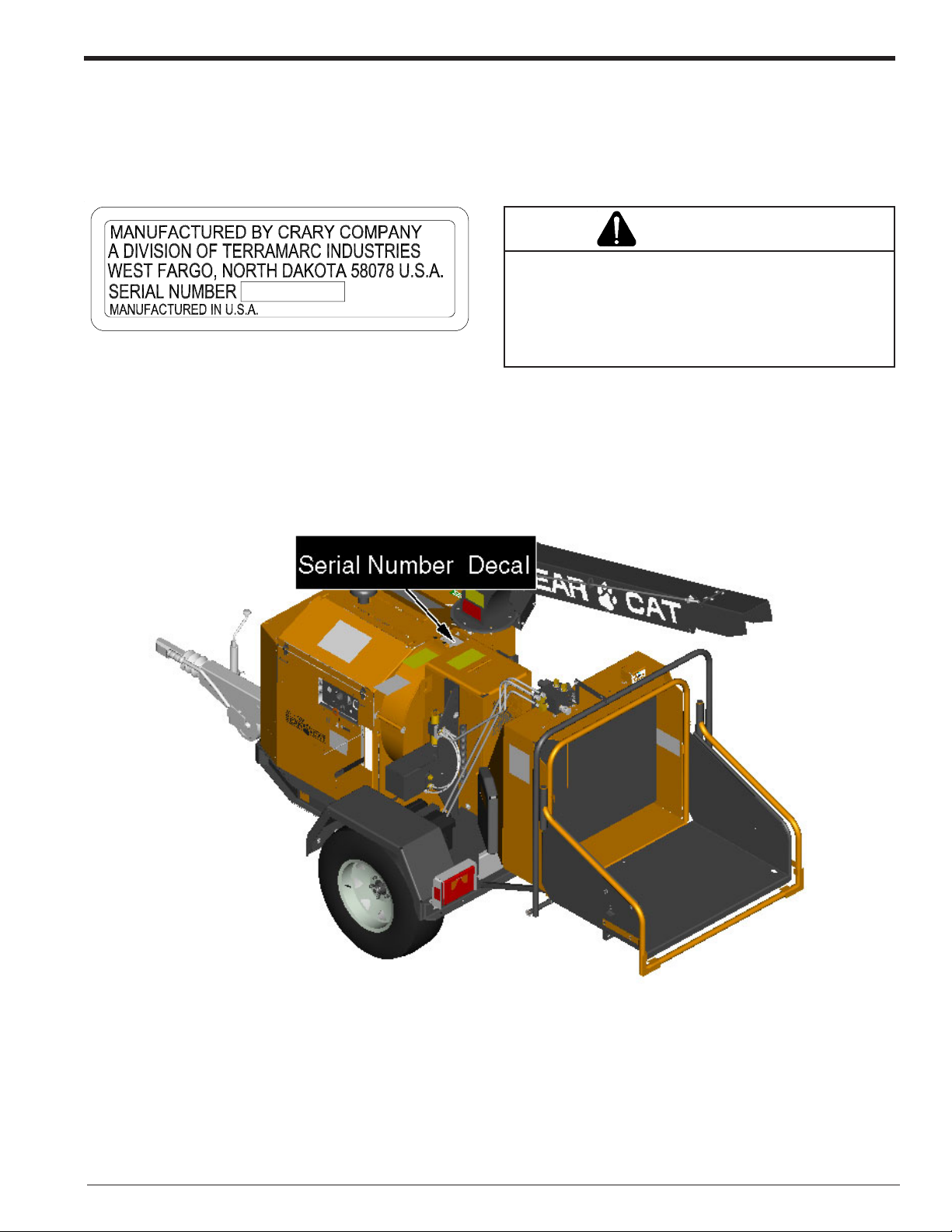
SERIAL NUMBER LOCATION
Always give your authorized Bear Cat dealer the serial number of your Crary Bear Cat chipper when ordering parts, requesting service or any other information. Please record the serial number in the space provided below and on the warranty and
registration card.
WARNING
To prevent personal injury or property damage: Shut
YXXXXX
Fig. # 1 Serial number decal
Serial Number ________________________
off engine, disconnect spark plug wire (if applicable),
make sure that all moving parts have come to a complete
stop, before obtaining serial number, servicing, adjusting
or repairing.
Fig. #2, Serial number decal
6" Chipper Operator’s Manual
I
Page 4

Section Description Page
SAFETY .................................................................................................................................... 1
1.1 THE SAFETY ALERT SYMBOL............................................................................................................. 1
1.2 BEFORE OPERATING .......................................................................................................................... 1
1.3 BEFORE OPERATING .......................................................................................................................... 2
1.4 OPERATION SAFETY ........................................................................................................................... 2
1.5 MAINTENANCE AND STORAGE SAFETY ............................................................................................ 3
1.6 FEED ROLLER SAFETY ....................................................................................................................... 3
1.7 MAINTENANCE AND STORAGE SAFETY ............................................................................................ 3
1.8 SAFETY DECAL LOCATIONS ............................................................................................................... 4
ASSEMBLY .................................................................................................................................... 5
2.1 ADDING MOTOR OIL TO ENGINE (ALL MODELS) ................................................................................ 5
2.2 ADDING HYDRAULIC FLUID ................................................................................................................. 5
2.3 ADDING COOLANT (DIESEL ONLY)...................................................................................................... 6
2.4 ASSEMBLY TORQUE CHART ............................................................................................................... 7
2.5 ATTACH THE TRAILER WHEELS.......................................................................................................... 8
2.6 ATTACHING THE DISCHARGE CHUTE ................................................................................................. 8
2.7 ATTACHING THE HITCH ........................................................................................................................ 9
2.8 INSTALLING THE REAR STABILIZER .................................................................................................... 9
2.9 ATTACHING THE BATTERY .................................................................................................................. 9
Contents
FEATURES AND CONTROLS .......................................................................................................................... 10
3.1 USE OF CONTROLS ........................................................................................................................... 11
OPERATION .................................................................................................................................. 12
4.1 FILLING THE TANK .............................................................................................................................. 13
4.2 STARTING THE GASOLINE CHIPPER ................................................................................................ 13
4.3 STARTING THE DIESEL CHIPPER ...................................................................................................... 14
4.4 HYD FEED CONTROL ......................................................................................................................... 14
4.5 CHIPPING .................................................................................................................................. 15
4.6 DIRECTING CHIPPER CHUTE ............................................................................................................. 16
4.7 FEED ROLLER BOTTLE JACK ............................................................................................................ 16
4.8 STOPPING INSTRUCTIONS ................................................................................................................ 16
4.9 SAFETY BAR OPERATION ................................................................................................................. 17
4.9.1 RESETTING THE CHIPPER ..................................................................................................... 17
4.9.2 LOCKING IN TRAVEL POSITION .............................................................................................. 17
SERVICE & MAINTENANCE ............................................................................................................................ 18
5.1 MAINTENANCE SCHEDULE ............................................................................................................... 18
5.2 REMOVING AND SHARPENING THE CHIPPER BLADES .................................................................. 19
5.3 REPLACING THE CHIPPER DRIVE BELT ........................................................................................... 20
5.4 REPLACING THE HYDRAULIC DRIVE BELT (HONDA ONLY) ............................................................. 21
5.5 GREASING .................................................................................................................................. 22
5.6 ADJUSTING CHIPPER ANVIL ............................................................................................................. 23
5.7 AIR FILTER (DIESEL SHOWN) ............................................................................................................ 23
5.8 CHECKING ANTIFREEZE (DIESEL) .................................................................................................... 23
5.9 HYD RESERVOIR FLUID .................................................................................................................... 24
5.10 HYD OIL FILTER ................................................................................................................................24
5.11 TRAILER SERVICE TIPS ................................................................................................................... 24
5.12 TROUBLESHOOTING ........................................................................................................................ 25
6" Chipper Operator’s ManualII
Page 5

NOTES
Page 6
Chipper Limited Warranty
Crary Bear Cat Chippers are warranted for one year from date of sale for consumer and commercial or
rental operations.
Within the above stated period, Crary Co. will replace any part(s) found to be defective in material and/or
workmanship, after the receipt of the part in our plant. Labor costs to replace these defective parts will be
paid at a Crary established labor rate and time allowed (flat rate) for repair. All transportation charges
incurred in shipping part(s) are the responsibility of the purchaser.
This warranty is void in the case of accidents, failure to perform normal maintenance, or failure to follow
those instructions listed in the service manual. This warranty is also in lieu of all other expressed warranties
and voids any implied warranty as to the merchantability or fitness of the product for a particular purpose
and of any other obligation on the part of Crary Co. Some states do not allow limitations on how long the
implied warranty lasts, so the above limitation may not apply to you.
This warranty applies only to parts or components which are defective, and does not cover necessary
repair due to normal wear, misuse, accidents, or lack of proper maintenance. Components subject to wear
such as wheels, hoses, cables, chipper blades, chipper anvils, etc., are not included in the warranty.
Regular routine maintenance of the unit to keep it in proper operating condition is the
responsibility of the owner.
Engine warranty is not covered by Crary Co. Rather the warranty is covered by the engine manufacturer.
All warranty repair reimbursable under the Crary Co. warranty must be performed by an authorized Bear
Cat service dealer using Bear Cat approved replacement parts. Repair or attempted repair by anyone other
than an authorized Bear Cat service dealer is not reimbursable under the Crary Co. warranty. In addition,
these unauthorized repair attempts may result in additional malfunction, the correction of which is not
covered by warranty.
Crary Co. is not liable for indirect, incidental, or consequential damages in connection with the use of this
product including any cost or expense or providing substitute equipment or service during periods of
malfunction or non-use.
Some states do not allow the exclusion of incidental or consequential damages, so the above exclusion
may not apply to you. This warranty gives you specific legal rights. You may also have other rights which
vary from state to state.
Be sure to note the chipper serial number in any correspondence with Crary Co. or any authorized Bear
Cat dealer.
Crary Company
A Division of TerraMarc Industries
237 12th St. NW • P.O. Box 849
West Fargo, ND 58078-0849
(701)282-5520 • FAX: (701)282-9522
www.bearcatproducts.com
www.terramarc.com
6" Chipper Operator’s Manual
III
Page 7
1
Safety
Section
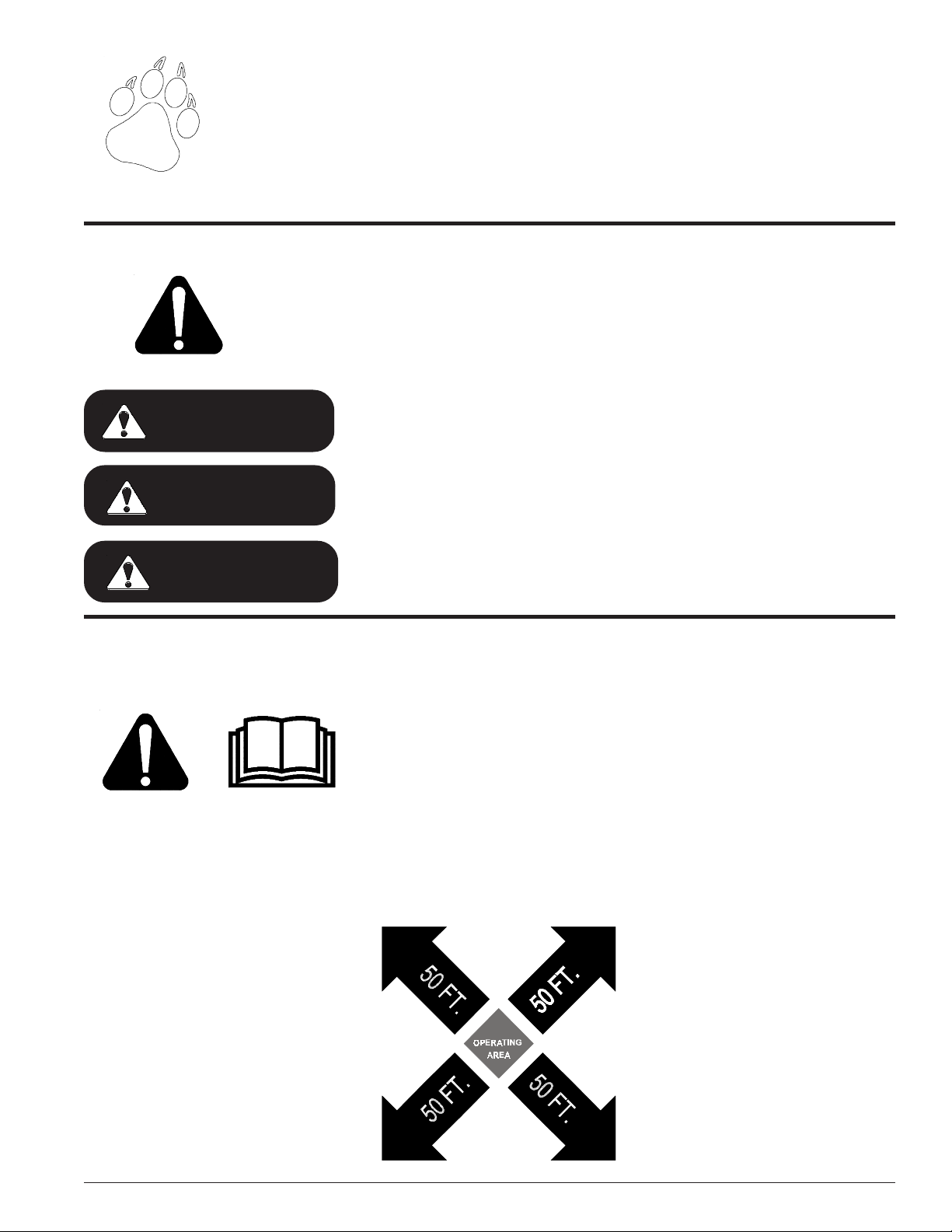
1.1 THE SAFETY ALERT SYMBOL
This manual and your machine uses this symbol to alert you of potential hazards.
When this symbol appears, read and obey the safety message that follows. Failure to obey the
safety message could result in personal injury, death or property damage.
Indicates an imminently hazardous situation that, if not avoided, will result in
DANGER
WARNING
CAUTION
death or serious injury.
Indicates a potentially hazardous situation that, if not avoided, could result in
death or serious injury.
Indicates a potentially hazardous situation that, if not avoided, may result in
minor or moderate injury.
1.2 BEFORE OPERATING
1. Read this Owner / Operator’s
manual carefully before operating
this equipment. Be completely
familiar with the controls and the
proper use of this equipment.
2. To prevent personal injury or death:
Stop chipper and engine.
Make sure that all moving parts
have come to a complete stop,
and disconnect quick couplers
from loader before servicing, adjusting or repairing.
3. Keep safety decals clean and legible. Replace missing or illegible
safety decals.
4. Familiarize yourself with all of the
safety and operating decals on this
equipment and on any of its attachments or accessories.
5. Do not allow children or any person unfamiliar with the unit to use
this machine.
6. Keep the area of operation clear of
all persons, particularly small children. Keep bystanders at least
50 feet (15 meters) away from the
operation area.
7. Do not operate this machine if
under the influence of alcohol,
medications, or substances that
can affect your vision, balance, and
judgement. Do not operate if tired
or ill. Only operate this machine
in good health.
8. Use only in daylight or good artificial light.
9. Never use without proper guards
in place.
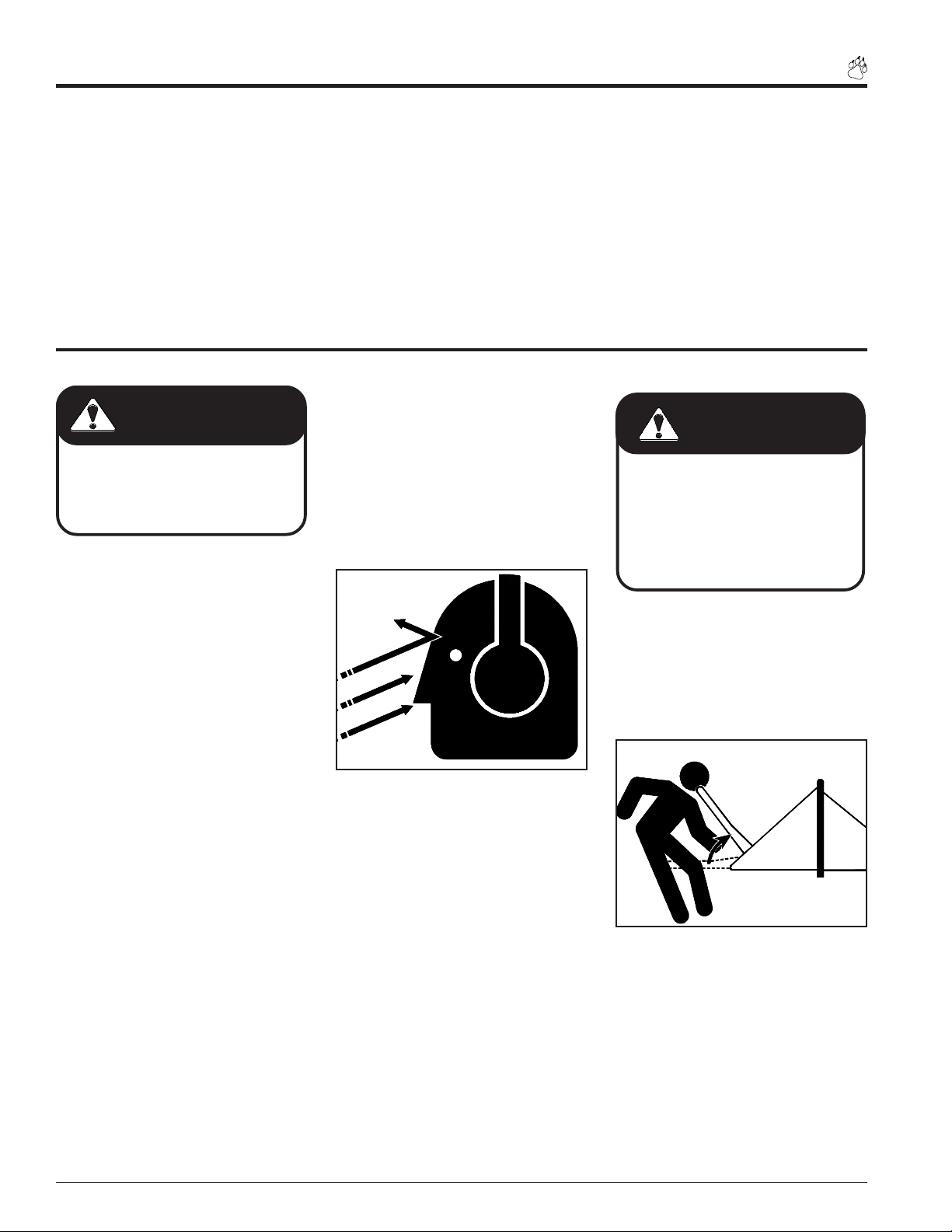
10. Wear safety glasses at all times
while operating this machine. Bear
Cat provides one pair of safety
glasses.
11. Wear hearing protection at all times
while operating this machine.
Page 16” Chipper Pro Operator’s Manual
Page 8
1.3 BEFORE OPERATING
Safety
12. Avoid wearing loose fitting clothing. Never operate this machine
wearing clothing with drawstrings
that could wrap around or get
caught in the machine.
1.4 OPERATION SAFETY
DANGER
Keep hands, feet and clothing out of
inlets and discharge openings while
operating the machine to avoid serious personal injury or death.
1. Do not allow hands, or any part of
body or clothing, inside the feeding
chamber, discharge chute, or near
any moving parts.
2. Check the cutting chamber to verify
it is empty before starting the machine.
3. Exclude pieces of metal, rocks,
bottles, cans, and other foreign objects when feeding chipable material into the machine.
4. Shut off machine immediately if the
cutting mechanism strikes any foreign object or the machine starts
making an unusual noise or vibrating. Allow the machine to stop completely. After machine stops:
13. Secure all screws, nuts, bolts, and
other fasteners before starting the
machine. Check once in the first
two hours and every 10 hours thereafter.
14. Keep all guards, deflectors, and
shields in place and in good working condition.
5. Do not allow processed material to
build up in the discharge area; this
may prevent proper discharge and
can result in kickback of material
through the feed opening.
6. Stand clear of the discharge area
when operating this machine.
7. Keep your face and body back from
the feed opening.
8. Do not climb onto chipper feed
chutes or frame when operating. Do
not overreach. Keep proper balance
and footing at all times.
15. While running the machine, do not
transport or move the machine.
WARNING
Material can kickup or shift suddenly
and cause serious injury or death.
• Wear eye and hearing protection.
• Stand to the side of the feed chute.
• Release material and stand to
side of the feed table and chute.
9. When feeding material into feed
roller:
A. Wear eye, face and hearing
protection.
B. Release material and stand to
side of feed table and chute.
WRONG
A. Shut off engine.
B. Remove ignition key.
C. Inspect for damage.
D. Replace or repair any
damaged parts.
E. Check for and tighten any
loose parts.
Page 2 6” Chipper Operator’s Manual
Page 9
WRONG
Safety
1.5 MAINTENANCE AND STORAGE SAFETY
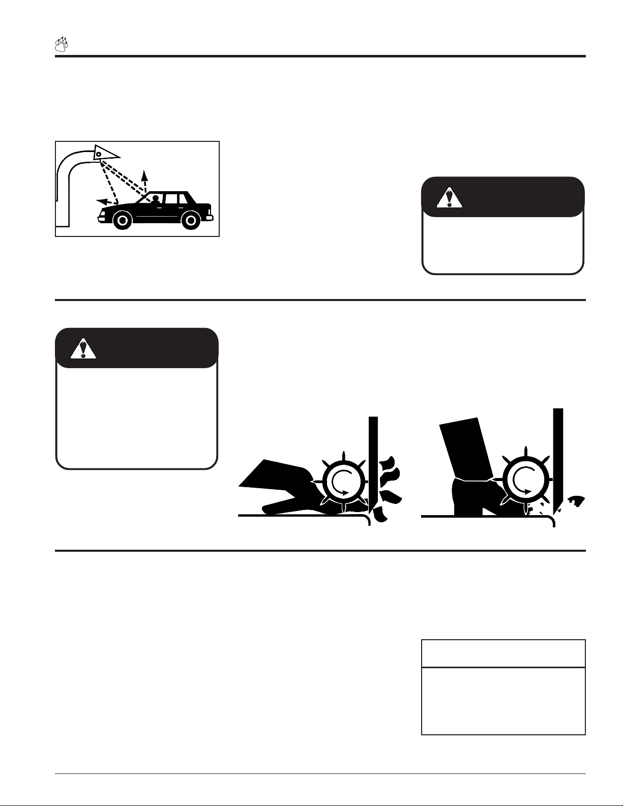
10. For safety purposes, set up your
chipping site as to not endanger
the public.
WRONG
1.6 FEED ROLLER SAFETY
WARNING
To prevent personal injury or death:
Stop chipper and loader engine.
Make sure that all moving parts
have come to a complete stop, and
disconnect quick couplers from
loader before servicing, adjusting,
or repairing.
11. Rotate the discharge tube to face
the opposite direction of the towing vehicle before towing. This
prevents the discharge tube from
projecting over the trailer wheels
and striking foreign objects.
12. Flying debris can cause serious
injury or death and property damage.
13. Keep bystanders away from discharge chute.
2. Never climb onto chipper feed
chute or table when operating.
3. Do not over reach. Keep proper
balance and footing.
WRONG
14. Position discharge chute away
from bystanders and other property when opening.
15. Check the bolts torque on the
chipper every 10 hours of operation.
WARNING
Failure to maintain proper fastening torque on chipper blade bolts
may result in severe damage to the
chipper and / or personal injury.
4. No riders allowed, keep off the at-
tachment.
1. Feed roller and rotating chipper
can cause serious injury or death.
Keep hands, feet and clothing
away from feed roller chipper
blades.
1.7 MAINTENANCE AND STORAGE SAFETY
1. Shut off machine, remove key, and
disconnect the spark plug wire when
servicing, inspecting or storing this
equipment.
2. Replace any missing or unreadable
safety decals. Refer to the parts
manual for part numbers when ordering safety decals from an area
Bear Cat dealer.
3. Store the machine out of reach of
children and where fuel vapors will
not reach an open flame or spark.
Drain the fuel and dispose of it in a
safe manner for storage periods of
three months or more.
4. Allow machine to cool before storing in an enclosure.
5. Never store this machine with fuel
in the fuel tank inside a building
where fumes may reach an open
flame or spark, or where ignition
sources are present such as furnaces, clothes dryers, stoves, electric motors, hot water and space
heaters, etc.
NOTE
See engine owners manual or contact the engine manufacturer for
engine safety instructions and decals.
Page 36” Chipper Pro Operator’s Manual
Page 10
Safety
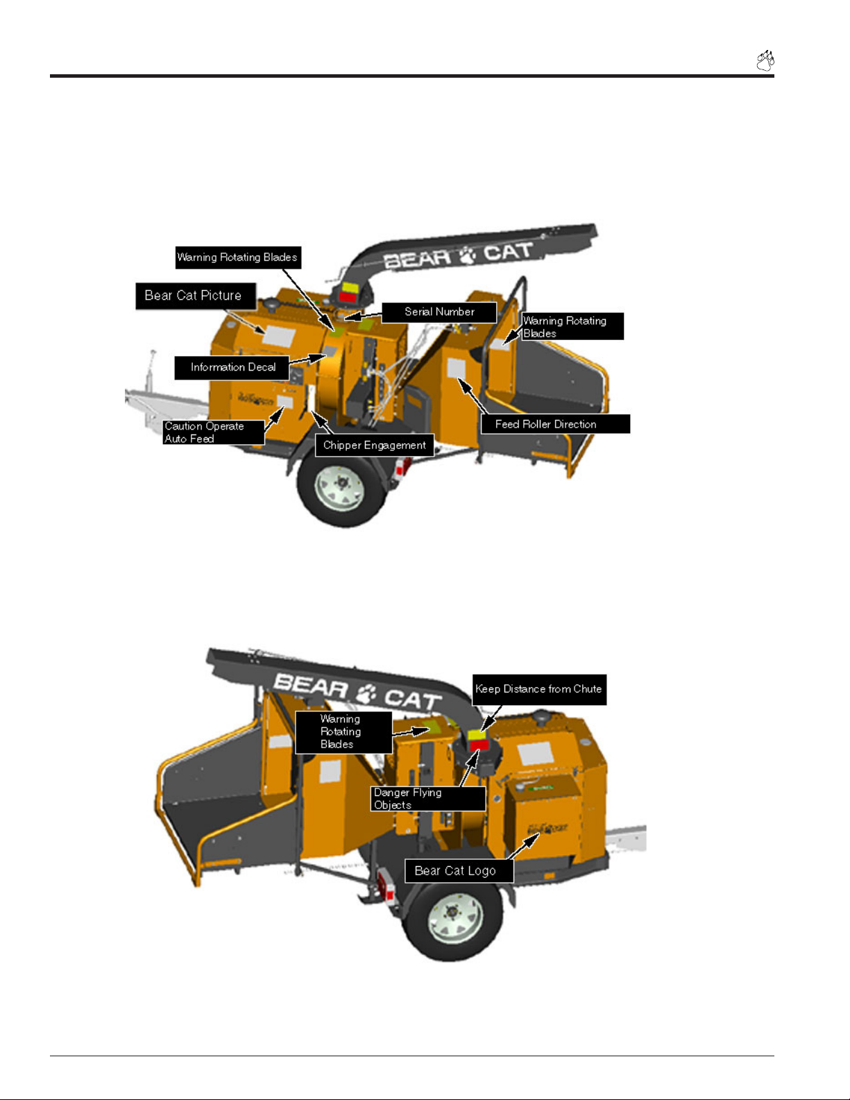
1.8 SAFETY DECAL LOCATIONS
Familiarize yourself with all of the safety and operational decals on the machine and the associated hazards. Keep all
safety decals and operational decals on this equipment clean and in good condition. If you need a replacement decal,
please refer to the parts catalog. Apply decals that need replacement to their original locations.
Fig. #3 Safety decal locations
Fig. #4 Safety decal locations
Page 4 6” Chipper Operator’s Manual
Page 11
2
Assembly
Section
Your Chipper may arrive totally or partially assembled. If
your machine arrives partially assembled, perform the steps
in this section.
2.1 ADDING MOTOR OIL TO ENGINE
(ALL MODELS)
1. The machine’s engine ships filled with oil from factory
testing.
2. Refer to the engine owners manual to determine oil type
used.
3. Remove the oil fill plug.
4. Checking as necessary, add oil to the motor until the
dipstick shows the correct reading.
IMPORTANT
Check motor oil before
starting the chipper. Add
if necessary.
3. Fill the inlet line leading from the reservoir to the pump before start-up. Loosen the fitting at the pump on this inlet line
until oil bleeds out.
4. Start the engine and run at the lowest possible RPM.
5. As you purge air from the unit, the oil level in the reservoir
will drop and bubbles may appear in the fluid. Refill the
reservoir as necessary.
6. Run the feed roller in both directions for several minutes
until any remaining air purges from the unit. Refill the reservoir as necessary.
7. Shut down the engine, check for and correct any fluid leaks,
and check the reservoir level. Add fluid if necessary. The
hydraulic gear pump is now ready for operation.
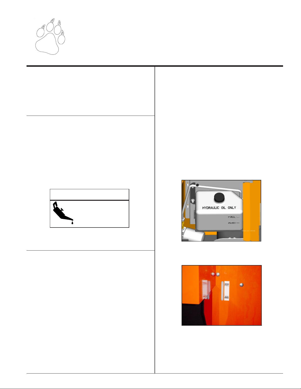
2.2 ADDING HYDRAULIC FLUID
Hydraulic fluid drives the feed roller. The hydraulic pump is
attached to the motor (diesel models) or connected to the
motor with a belt (gasoline models).
The hydraulic pump requires premium hydraulic fluids
containing high quality rust, oxidation, and foam inhibitors.
These include premium turbine oils, API CD engine oils per
SAE J183, M2C33F or G automatic transmission fluids
meeting Allison C-3 or Caterpillar TO-2, and certain specialty
agricultural tractor fluids.
If system has no oil, follow this startup procedure:
1. Clean all system components (reservoir, fittings, etc.)
before starting the hydraulic pump.
2. After filtering the hydraulic fluid, fill the hydraulic reservoir.
Figure #5 Hydraulic reservoir (Honda Engine)
Figure #6 Hyraulic reservoir (Kubota Engine)
Page 56” Chipper Pro Operator’s Manual
Page 12

2.3 ADDING COOLANT
(DIESEL ONLY)
You may need to add coolant before you start the diesel
engine. While operating, check the fluid to ensure the level
sits between the full and the low marks. Add if necessary.
To fill:
1. Remove the top cover.
2. Add a 50/50 mix of water and antifreeze until it reads
slightly below the full line. (The antifreeze should drain
from the tank into the radiator).
3. Wait 10 minutes and check level again. Refill if necessary.
4. After running the machine, recheck the level of antifreeze,
and fill if necessary.
Assembly
Fig. #7 Coolant level
Page 6 6” Chipper Operator’s Manual
Page 13

Assembly
2.4 BOLT TORQUE
CHECKING BOLT TORQUE:
The table shown below is for reference purposes only and its use by anyone is entirely voluntary, unless otherwise noted.
Reliance on its contents for any purpose is at the sole risk of that person. BearCat Co. is not responsible for any loss claim
or damage arising there from. In developing these tables, BearCat has made a determined effort to present the contents
accurately.
SAE - 8SAE - 2ASAE - 5
ENGLISH TORQUE SPECIFICATION
Bolt
Diameter
"A"
1/4" 7.5 5.5 11 8 16 12
5/16"151123173425
3/8" 27 20 41 30 61 45
7/16"413068509570
1/2" 68 50 102 75 149 110
9/16" 97 70 149 110 203 150
5/8" 122 90 203 150 312 230
3/4" 217 160 353 260 515 380
7/8" 230 170 542 400 814 600
1" 298 220 786 580 1220 900
1-1/8" 407 300 1085 800 1736 1280
1-1/4" 570 420 2631 1940 2468 1820
METRIC TORQUE SPECIFICATION
Bolt
Diameter
"A"
M30.50.4 - - - - - M432.2 - - - - - M554 - - - - - M6 6 4.5 11 8.5 17 12 19 14.5
M8 15 11 28 20 40 30 47 35
M102921554080609570
M1250379570140105165120
M14 80 60 150 110 225 165 260 190
M16 125 92 240 175 350 255 400 300
M18 175 125 330 250 475 350 560 410
M20 240 180 475 350 675 500 800 580
M22 330 250 650 475 925 675 1075 800
M24 425 310 825 600 1150 850 1350 1000
M27 625 450 1200 875 1700 1250 2000 1500
SAE 2 SAE 5 SAE 8
N.m Ft-lb N.m Ft-lb N.m Ft-lb
A
4.8 8.8 10.9
N.m Ft-lb N.m Ft-lb N.m Ft-lb N.m Ft-lb
Bolt Torque* (UNC)
Bolt Torque*
12.9
Torque figures indicated above are valid for non-greased or non-oiled threads and heads unless otherwise specified. Therefore, do not grease or
oil bolts or capscrews unless otherwise specified in this manual. When using locking elements, increase torque values by 5%.
* Torque value for bolts and capscrews are identified by their head markings.
Page 76” Chipper Pro Operator’s Manual
Page 14

Assembly
2.5 ATTACH THE TRAILER WHEELS
1. Remove the chipper from its shipping crate. Place the
unit on a level surface before attempting to assemble it.
See the torque on the previous page for tightening torque
of bolts and screws.
2. Raise the trailer several inches from the ground with a
hoist or jack. Support the chipper securely.
3. Lift one wheel to a hub and align the wheel lug holes with
the hub lug bolts. Thread the lug nuts (found in the parts
kit) into the holes and tighten the lug nuts to 75 ft. lbs.
Follow a star pattern when tightening the lug nuts. Repeat this step for the remaining wheel.
2.6 ATTACHING THE DISCHARGE
CHUTE
1. The chute rotator connects to the chipper frame first with
two 3/8 bolts from the owners kit. Install but do not tighten.
Remove the top cover from the chute rotator to expose
the rotator drive sprocket.
2. Attach the discharge chute to the mounting flange on the
chipper frame. The square discharge chute will fit over
the round section of the chipper frame.
3. Place the discharge ring, and discharge retainer around
the base of the mounting flange on the chipper frame.
4. Attach the discharge ring and retainer to the flange with
the provided 3/8” x 1-1/4” bolts and nuts. Tighten to proper
torque.
5. Install the chain around the discharge ring and sprocket
on the inside of the chute rotator. Connect chain with the
connector link.
6. Reassemble the top cover and tighten the 4 bolts.
Fig. #8 Trailer wheels
7. Slide the chute rotator assembly back to remove chain
slack and tighten the two attachment bolts.
8. Torque all fasteners to proper values.
Fig. #9 Discharge chute
Page 8 6” Chipper Operator’s Manual
Page 15

Assembly
2.7 ATTACHING THE HITCH
1. Attach the channel spacer over the square tube.
2. Attach the ball coupler over the channel spacer to the
hitch weldment using the provided 1/2” x 4” bolts and 1/2”
washers and 1/2” nuts. Tighten to proper torque.
3. Slide the hitch weldment into the hole in the frame, back
to the 1/2” mounting holes.
4. Connect the hitch weldment to the frame using the two 1/
2” x 4-1/2” bolts, 1/2” washers and 1/2” nuts. Tighten to
proper torque.
5. Check the tongue jack and safety chains for correct
installation.
2.8 INSTALLING THE REAR STABILIZER
Install the rear stabilizer by sliding the stabilizer into the
corresponding slot on the rear of the chipper frame. Secure
and adjust the stabilizer with the provided snap pin.
Fig. #11 Rear stabilizer
Fig. #10 Trailer hitch
2.9 ATTACHING THE BATTERY
A battery ships with the chipper. Connect the battery cables
to the battery using the two 1/4” bolts and nuts found in the
parts kit. To connect:
1. Route the battery cables to the proper battery terminals,
hooking positive to positive, and negative to negative.
2. Connect cables with 1/4” bolt and nuts. Tighten nuts to
proper torque.
3. Check battery for proper fluid level and fill if necessary.
4. If necessary, charge battery.
Page 96” Chipper Pro Operator’s Manual
Page 16

3
Features and Controls
Section
FEATURES AND CONTROLS IDENTIFICATION
Learn the location of the features and controls on your machine before operating.
Fig. #12 features and controls
Fig. #13 features and controls
DESCRIPTION OF OPERATION
The chipper pulls in wood with the feed roller, chips the wood, and blows the chips out through the adjustable discharge
chute.
Page 10 6” Chipper Operator’s Manual
Page 17

Features & Controls
3.1 USE OF CONTROLS
WARNING
To prevent personal injury or property damage: Shut
off engine, remove key, and make sure that all moving
parts have come to a complete stop, before servicing,
adjusting or repairing.
1. Key: The control panel houses the key on both the diesel and gas engines. Turn the key to the right to activate the electric start. On diesel models turning the key
to the left activates the glow plug. DO NOT START THE
MACHINE WITH THE CHIPPER ENGAGED.
2. Throttle: This controls the speed of the engine. On diesel models adjust the throttle by twisting, or by pushing
the button and pushing or pulling.
3. Choke: Use this to start the gasoline engine when cold.
Move cable to original position as engine warms.
4. Chipper Engagement: To activate slowly push the
handle toward the ground. To disengage the machine
move the handle back up to the original position (See
Fig. #16).
5. Feed Roller Engagement: To engage the feed roller
move the control arm. The cycle of the control arm,
forward to back, is R, F, N, R.
6. Chute Rotor: Directs the discharge of chipped material
horizontally.
Fig. #14 Diesel controls
Fig. #15 Gasoline controls
7. Discharge cap rotor: Directs the discharge of material
vertically.
8. Rear Stabilizer: Prevents the chipper from tipping from
heavy loads when disconnected from the towing vehicle.
9. Bottle Jack: Used to lift feed roller for unplugging.
10. Tongue Jack: Used to adjust the height of the hitch.
11. Fuel Gauge: Shows remaining fuel.
12. Murphy Switch: See starting instructions for diesel
engines. The murphy switch prevents the engine from
running with low oil pressure, or high engine temperature. To start the engine, hold the switch until the oil
pressure appears on the gauge.
Fig. #16 Engagement instructions
Page 116” Chipper Pro Operator’s Manual
Page 18

4
Operation
Section
WARNING
Before operating your machine, be
sure you read and understand all
safety, controls and operation instructions in this Owner/Operators
manual and on your machine.
Failure to follow these instructions
can result in serious injury or property damage.
As with any other piece of outdoor
power equipment, getting the “feel” for
how your machine operates and getting
to know the best techniques for
particular jobs are important to overall
good performance.
Read this section thoroughly before you
start the engine. The instructions given
here will help you become familiar with
your machine and have you operating
efficiently in a short time.
This section covers:
• Filling the tank (Gas and diesel instructions)
• Starting the gasoline chipper
• Starting the diesel chipper
• Hydraulic feed
• Chipping
• Directing the chipper chute
• Feed roller bottle jack
• Stopping Instructions
• Safety Bar Operation
Fig. #17 Chipping
Page 12 6” Chipper Operator’s Manual
Page 19

Operation
4.1 FILLING THE TANK
DANGER
Gasoline is highly flammable and its vapors are explosive. To prevent personal injury or property damage:
Store gasoline only in approved containers, in well ventilated, unoccupied buildings, away from sparks or flames.
Do not fill the fuel tank while the engine is hot or running,
since spilled fuel could ignite if it comes in contact with
hot parts or sparks from ignition. Do not start the engine
near spilled fuel. Never use gasoline as a cleaning agent.
FILLING THE FUEL TANK
Gasoline Type:
For best results use only clean, fresh, unleaded gasoline
with a pump sticker octane rating of 87 or higher. In countries using the Research method, use a 90 octane minimum.
WARNING
Handle fuel with care. It is highly flammable. Always use
an approved container and fill tank outdoors.
CAUTION
Move machine to a clear level area. Do not operate in
the vicinity of bystanders.
4.2 STARTING THE GASOLINE CHIPPER
Make sure the chamber is empty before starting.
1. Reference the Honda Owners Manual.
2. Check engine oil level before starting. Do not overfill or
underfill oil. The Honda engine is equipped with an oil
level sensor and will not allow the engine to start in either
condition.
Gasoline Alcohol blends
Gasohol (up to 10% ethyl alcohol, 90% unleaded gasoline
by volume) is approved as a fuel for Honda engines. Other
gasoline/alcohol blends are not approved.
Gasoline Ether blends
Methyl Tertiary Butyl Ether (MTBE) and unleaded gasoline
blends (up to a maximum of 15% MTBE by volume) are
approved as a fuel for Honda engines. Other gasoline/ether
blends are not approved.
Diesel Fuel:
For best results use only clean, fresh, #2 diesel. Use an
additive for cold weather to prevent the fuel from turning into
a gel.
To Add Fuel:
1. Stop engine, wait for all parts to stop moving, then remove the key. Allow the engine and muffler to cool for at
least three minutes.
2. Clean area around fuel fill cap and remove cap.
3. Place the chipper engagement in the start position.
4. Engage the choke if necessary.
5. Adjust throttle to start/idle position.
6. Turn the key to the right to engage the starter.
7. Release the key after the engine starts.
8. For a Cold Engine — Gradually return the choke from
the choke position to the run position as the engine warms
up.
3. Using a clean funnel, fill fuel tank to 1/2” below bottom of
filler neck to provide space for fuel expansion. Install fuel
fill cap securely and wipe up any spilled diesel.
Page 136” Chipper Pro Operator’s Manual
Page 20

Operation
4.3 STARTING THE DIESEL CHIPPER
WARNING
Allow the machine to come to complete stop before inspection or servicing.
WARNING
Handle fuel with care. Always use an approved container
and fill tank outdoors.
CAUTION
Move machine to a clear, level area. Do not operate in
the vicinity of bystanders.
NOTE
The Murphy switch system will shut the engine off if
the oil pressure is too low or if the engine temperature
is too high. If the engine will not run or shuts off for
these reasons, consult your local dealer.
4.4 HYD FEED CONTROL
1. Reference the Kubota Owners Manual. Before starting,
empty the cutting chamber.
2. Before starting, fill engine with oil to the correct level.
See engine manual for additional starting, operation and
maintenance instructions. Some oil usage is normal.
Check level before each use.
3. Before starting, fill fuel tank with fresh and clean diesel
fuel. For instructions on bleeding the fuel system on initial start up or if fuel runs out, see engine manual.
4. Turn key switch to preheat position (to the left). Hold in
preheat position for several seconds until glow plug indicator light switches off.
5. Place throttle control in the idle position.
6. Disengaged the chipper engagement lever.
7. Push in and hold the Murphy switch push-button. Continue to hold Murphy switch in when cranking engine until engine runs.
8. Activate the starter. Release the switch as soon as the
engine starts. Do not crank over for more than 10 seconds. After starting the engine; hold the Murphy switch
until engine has oil pressure.
Fig. #18 Controller
A pre-programmed hydraulic feed control equips the Bear
Cat chipper. The controller serves a variety of functions
including monitoring chipper rotor RPM, controlling the feed
roller, and providing routine maintenance alerts. The controller
has an on/off feature located below the control panel. If the
controller becomes damaged, the chipper will still run with
the controller shut off, however all of the controller functions
will be disabled. The control arm will control the feed roller.
The controller is positioned under the control panel.
The controller functions are further detailed below:
1. The controller operates the feed roller. The controller monitors the RPMs of the chipper rotor and if it drops below
the preset range the feed roller stops. When the RPMs
reach an acceptable level, the feed roller will reengage.
2. The controller also has a “try again” feature. The controller monitors the hydraulic pressure of the feed roller. If it
senses the level is too high (the feed roller becomes obstructed) the controller will reverse the feed roller , removing the material trying to be chipped. The controller will
then engage the roller into the forward position and try to
feed the material again. If this cycle continues, remove
the obstruction manually. Trim or reposition material if
necessary.
Page 14 6” Chipper Operator’s Manual
Page 21

Operation
4.4 HYD FEED CONTROL (CONT’D)
3. The controller will also flash service alerts when started.
Every 15 hours it will flash (error light blinks 5 times) to
sharpen the chipper blades. Every 100 hours it will flash
(error light blinks 10 times) to change the engine oil. To
reset service alerts, locate light green wire in engine compartment next to the hour meter. Connect green wire to
red wire connector for five seconds.
NOTE: The RPM sensor on the rotor must flash or the
controller won’t work. Clearance between the sensor and
the bolt must be between 1/32” and 3/32”.
4.5 CHIPPING
WARNING
Obtain and wear safety glasses at all times when operating the machine. Do not wear loose fitting clothing.
Use common sense and practice safety to protect yourself from branches, sharp objects and other harmful objects.
5. Never use shovels or forks to push brush. They can go
through the chipper and cause major damage. In addition, metal pieces can come back like shrapnel to injure
or kill.
6. Never push brush into the chute with your feet.
7. Engage the hydraulic feed by moving the control arm.
Pull the arm toward you to engage the hydraulic feed.
Adjust the speed of the feed roller by turning the speed
control knob on the chipper valve assembly.
8. Place limb, butt end first, into the chipper chute until it
contacts the hydraulic feed roller and draws into the chipper blades. The actual feed rate of the limb into the chipper will depend on the type of material fed, and sharpness of the cutting blades.
9. If the feed roller slips, increase the downward pressure on
the roller by moving the eyebolt that connects the spring
to the feed roller.
10. Alternate greener material with dry material to lubricate
the chipping blades for longer life and better performance.
When the chipping blades become dull, they will require
periodic sharpening. Refer to Service and Maintenance,
"Sharpening Chipper Blades."
The Bear Cat chipper chips a variety of materials into a
more readily decomposing or handled condition. Use the
following guidelines to help get started.
Please read and follow all safety instructions in this manual.
Failure to operate the chipper in accordance with the safety
instructions MAY RESULT IN PERSONAL INJURY!
1. Before chipping material, engage the unit to full operating
speed. Adjust engine speed with the throttle. Diesel models have the option of locking the throttle.
2. Select limbs up to 6 inches in diameter. Trim side
branches that do not bend enough to feed into the chipper chute. Hold small diameter branches together in a
bundle and feed in simultaneously.
3. Feed brush from the side of the chute, rather than from
the front. Step aside to avoid being hit by the brush moving into the chipper.
4. Never lean over the chute to push objects into the cutting
device. Use a push stick or brush paddle.
Page 156” Chipper Pro Operator’s Manual
Page 22

4.6 DIRECTING CHIPPER CHUTE
Operation
The chipper chute can lock into 44 different positions using
the chute rotator. The chipper chute will lock before it revolves
over the feed chute area. The discharge cap adjusts how
high and how far the chipped material blows.
To adjust the chute rotor lift up the rotor lock. Turn the chute
rotor until the chute faces the desired position. Let go of the
rotator lock and fine tune the position of the rotor until the
lock snaps in place.
Adjust the discharge cap by turning the discharge crank
cap either clockwise or counterclockwise. Turning the handle
clockwise will raise the position of the discharge cap. Turning
the handle counterclockwise will lower the position of the
discharge cap.
Before entering feed chute for service or removal of material,
place the safety pin in the lock position. This will prevent the
feed roller from dropping and causing injury or death.
Turning the check valve clockwise will engage the pump of
the jack. Once you engage the jack the pumping the handle
will raise the jack. Turning the check valve counterclockwise
will disengage the pump and lower the jack.
Fig. #19 Directing the chute
4.7 FEED ROLLER BOTTLE JACK
Fig. #20 Bottle jack
Use the feed roller bottle jack to raise the feed roller if chipping
material becomes wedged in the feed roller. The jack will
raise the feed roller and remove the tension on the chipped
material.
Figure # 21 Safety Pin in Lock Position
4.8 STOPPING INSTRUCTIONS
WARNING
Allow the machine to come to complete stop before
inspection or servicing.
1. Move throttle to slowest position.
2. Move chipper engagement to the engine start position.
3. Let machine idle for a few seconds.
4. Turn key to off position.
5. Allow machine to come to a complete stop.
Page 16 6” Chipper Operator’s Manual
Page 23

Operation
4.9 SAFETY BAR OPERATION
4.9.1 Resetting the Chipper
The safety bar located around the chute area will stop the
chipper when pushed in. The reset button for this bar sits on
top of the chipper chute. To reset the safety bar, push the
reset button and the machine will start up again. If false trips
occur from a limb, the reset button can be held in to override
the system. Upon start up, safety bar light will be on and will
require the reset button to be pushed in before the feed roller
will operate. When the safety bar has been activated, a red
light will be on signaling that the operator reset button will
need to be pushed before feed roller will function.
4.9.2 Locking in Travel Position
The safety bar will lock into travel position. Place the extension tray in an upright position. Pushing the safety bar down
will lock the safety bar (see Figure # 23). To unlock, lower
the extension tray and push in on the safety bar. This will
release the flange and allow the safety bar to move freely.
Figure # 23 Flange lock
Figure # 22 Safety Bar, Reset Button
Page 176” Chipper Pro Operator’s Manual
Page 24

5
y
p
p
y
Service & Maintenance
Section
5.1 MAINTENANCE SCHEDULE
Check the following items listed in the service and mainte-
WARNING
nance schedule and if necessary, take corrective action.
This schedule is designed for units operating under normal
conditions. If the unit operates in adverse or severe usage
conditions check and service items more frequently.
See engine owners manual for further maintenance and
troubleshooting information.
SERVICE AND MAINTENANCE SCHEDULE
COMPONENT
AIR CLEANER CHECK AND CLEAN (1)
AIR INTAKE CLEAN (1)
ENGINE OIL CHANGE (1)
FUEL FILTER REPLACE
SPARK PLUG
ENGINE OIL CHECK
FUEL TANK FILL
CHIPPER ANVIL
CHIPPER BLADES
ALL INTERNAL AND
EXTERNAL NUTS AND
BOLTS
BELT CONDITION CHECK
BELT TENSION CHECK
GREASE ZERKS LUBE
ENTIRE MACHINE CLEAN
HYD. OIL FILTER REPLACE
WHEEL BEARINGS CHECK AND REPACK
(1) PERFORM MORE FREQUENTLY UNDER EXTREMELY DUSTY CONDITIONS.
(2) PERFORM MORE FREQUENTLY WHEN CHIPPING DRY OR DIRTY WOOD.
As the Chipper Limited Warranty states, failure by the Owner to perform normal maintenance will void the machine's
warrant
NORMAL MAINTENANCE. S
INTERNAL AND EXTERNAL NUTS AND BOLTS is the sole res
cause for Crar
. The aggressive, high-speed nature of chipping REQUIRES THE OWNER TO PERFORM THE ABOVE LISTED
BearCat to deny warranty.
MAINTENANCE
REQUIRED
CHECK CONDITION AND
GAP
CHECK 1/16" TO 1/8"
CLEARANCE AND RETORQUE TO 75 FT. LBS. (2)
CHECK SHARPNESS AND
RETORQUE TO 75 FT. LBS.
(2)
RE-TORQUE PER
ASSEMBLY TORQUE CHART
ecial consideration to maintain and re-torque the CHIPPER ANVIL, CHIPPER BLADES, AND ALL
Refer to Engine
Operator manual
•
To prevent personal injury or property damage: Shut
off engine, disconnect spark plug wire and make sure
that all moving parts have come to a complete stop
before, servicing, adjusting or repairing.
FREQUENCY
EVERY 8
HOURS
EVERY
25
HOURS
EVERY
50
HOURS
•
•
•
onsibility of the Owner. Failure by the Owner to do so shall be
EVERY
200
HOURS
EVERY
YEAR
Page 18 6” Chipper Operator’s Manual
Page 25

Service & Maintenance
5.2 REMOVING AND SHARPENING
THE CHIPPER BLADES
WARNING
To prevent personal injury or property damage: Shut
off engine, remove ignition key and make sure that all
moving parts have come to a complete stop before servicing, adjusting or repairing.
WARNING
The chipping blades are sharp!! Use care when working
on the machine to avoid injury.
To remove the chipping blades for sharpening:
1. Remove the two 3/8 inch retaining bolts holding access
cover to main frame assembly.
2. Tilt access cover over to allow rotor access. The chipper
will not operate with an open cover. Rotate the rotor to
access the bolts holding the blades. To remove the blades,
open the access cover from the top of the feed roller.
3. Remove the two allen head bolts holding the blade itself.
Repeat for all four blades. The four chipping blades have
two edges per blade and can be reversed one time each
before sharpening. Tighten bolts to proper torque and secure access cover.
Sharpening the chipper blades:
Depending on the type of wood fed into the chipper, the
blades will eventually dull, making it difficult to feed material
and produce chips. Check the blades for sharpness every 8
hours.
Regrind the angled edge of the chipping blades to 45 degrees.
(refer to figure below) Grind the blades on a bench grinder or
by a professional. Use some type of fixture to correctly hold
the blade at the proper angle. Be careful when grinding so
that the blade does not become overheated and change
color (This will remove the heat-treated properties). Use short
grinding times and cool with water or some type of liquid
coolant. Try to remove an equal amount off of each blade to
maintain rotor balance. The blades can receive up to
approximately 6 sharpenings depending on the amount of
material removed to restore a razor-sharp edge.
Never sharpen or back grind the flat side of the chipping
blade. This will cause the edge to roll and damage the chipper
blade, resulting in poor chipping performance.Small
imperfections such as nicks, burrs, etc. on the blade may
affect the chipping performance of the machine. Sharpen
the blade to remove imperfections. Replace the blade if
imperfections are too large.
Replace the blade after the allotted sharpening amount dips
below the chipper outlet (See Fig. 25 “A”). If you do not
replace the blade, damage to the machine will occur due to
pieces of wood jamming into the chipping disk and blade.
When completed, replace the chipping blades and tighten
the bolts to 75 ft. lbs. Install all safety screens and guards
and resume chipping.
CHIPPER
SHARPENED
SURFACE
CHIPPING
DISC
A
OUTLET
SHARPENED
SURFACE
Fig. # 24 Exposing the chipper blades
.38
45°
Figure # 26 Imperfections that require replacement
MOUNTING SURFACE
DO NOT GRIND
Fig. # 25 Sharpening the chipper blades
ALLOTTED
SHARPENING AMOUNT
.13
Page 196” Chipper Pro Operator’s Manual
Page 26

5.3 REPLACING THE CHIPPER
DRIVE BELT
Service & Maintenance
Fig. # 27 Idler pulley
Check the condition of the drive belt annually, or after every
25 hours of operation. Replace the belt if cracked, worn,
frayed, or stretched. Only replace it with the original banded
belt type, do not use singe belt types.
To replace the belt:
1. Remove idler pulley. Remove the pulley by loosening the
1/2” mounting hardware.
2. Lift belt idler pulley off of the idler arm weldment.
3. Remove the drive belt from the pulleys and take the old
belt out of the machine.
4. Install new belt on pulleys and lower belt idler. Check
alignment of pulleys and adjust if needed.
5. Reinstall the belt idler pulley to the idler arm weldment
using the 1/2” hardware. Tighten bolt to proper torque.
Fig. # 28 Removing the belt
5. Check belt tension before start-up. If necessary adjust
spring tension.
Page 20 6” Chipper Operator’s Manual
Page 27

Service & Maintenance
5.4 REPLACING THE HYDRAULIC
DRIVE BELT (HONDA ONLY)
Check the condition of the hydraulic drive belt annually, or
after every 25 hours of operation. Replace the belt if cracked,
worn, frayed, or stretched.
To replace:
1. Loosen the mounting bolts shown in Fig. #29.
2. Loosen the nut (not shown) on the back side of the adjusting bolt to relieve tension on the belt. Make sure that
the pump mounting bracket moves and relieves the belt
tension.
3. Remove drive belt according to instructions on prior page.
4. Remove the loosened hydraulic belt from the chipper.
5. Install the new hydraulic belt in the same manner as you
removed the old belt.
6. Replace the drive belt, according to directions on prior
page.
7. Install the hydraulic drive belt onto the two pulleys.
8. Tighten the nuts on the adjusting bolt to move the pump
mounting bracket. Stop when the belt is at the desired
tension.
9. Tighten the mounting bolts on the pump mounting bracket
to the proper torque.
10. Check pulleys for proper alignment and adjust if neces-
sary.
Fig. # 29 Hydraulic pump
Page 216” Chipper Pro Operator’s Manual
Page 28

5.5 GREASING
Grease zerks on the Bear Cat 6” Chipper every 25 hours,
depending upon conditions.
Service & Maintenance
Fig. # 30 Greasing
Fig. # 32 Greasing
Fig. # 33 Greasing
Fig. # 31 Greasing
Page 22 6” Chipper Operator’s Manual
Page 29

Service & Maintenance
5.6 ADJUSTING CHIPPER ANVIL
5.7 AIR FILTER (DIESEL SHOWN)
Fig. # 35 Diesel Air Filter
Both the Kubota diesel and the Honda gas engines used on
the 6” chipper have air filters. Refer to the Kubota and Honda
engine manuals, included with your machine, for specific
instructions on replacing and cleaning these filters.
Fig. # 34 Chipper anvil
The four chipping blades should clear the chipper anvil by 1/
16 inch to 1/8 inch. The chipper anvil is adjustable and
reversible. Use all four sides of the anvil for chipping.
To adjust:
1. Lift rotor access cover and expose rotor.
2. Loosen the three 1/2 inch bolts that hold the chipper anvil
to the frame.
3. Measure the amount of clearance between chipping blade
and chipper anvil from inside of housing.
4. Adjust inward or outward to the desired measurement,
using the adjustment nuts provided.
5. Tighten bolts on chipping block to 75 ft. lbs. and resume
operation.
If damage or uneven wear occurs on chipper anvil edge,
remove the three bolts holding the anvil and use one of the
other three edges. Replace as necessary.
5.8 CHECKING COOLANT (DIESEL)
Fig. # 36 Diesel coolant level
The diesel Kubota is tested before shipping. In order to test
the equipment the fluid levels are filled. However, before
starting the machine, check the coolant level. Add fluid if
the level is low.
To add fluid follow the procedure below:
1. Make sure the coolant isn’t hot.
2. Open the radiator cap pictured in Fig #36.
3. Check level and add if necessary. Use a 50/50 mixture of
antifreeze and water.
Page 236” Chipper Pro Operator’s Manual
Page 30

Service & Maintenance
5.9 HYD RESERVOIR FLUID
Fig. # 37 Hydraulic reservoir (Honda Engine)
The chippers are tested before shipping. In order to test the
equipment the fluid levels are filled. However, check the fluid
levels before initial operation and add if necessary (see the
assembly section). Always check levels before each use.
To check levels look at the side of the hydraulic oil container
and make sure the fluid level falls between the marks. If
necessary add oil.
On the Kubota models the hydraulic tank sits next to the
fuel tank. A cutout exists to check the fluid level.
Premium hydraulic fluids containing high quality rust,
oxidation and foam inhibitors are required. These include
premium turbine oils, API CD engine oils per SAE J183,
M2C33F or G automatic transmission fluids meeting Allison
C-3 or Caterpillar TO-2, and certain specialty agricultural
tractor fluids.
5.10 HYD OIL FILTER
Fig. # 39 Hyd oil filter
Change this filter after the first 50 hours and every 200 hours
thereafter. To change:
1. Using an oil filter wrench turn the filter counterclockwise.
2. Once the filter becomes loose, turn it out the rest of the
way with your hand.
3. Properly discard old filter.
4. Lube the rubber seal on the new filter (P/N 16588) with
clean hydraulic oil.
5. Install the filter onto the threaded pipe. Turn with your
hand until the filter is finger tight.
6. Turn, by hand, another 1/2 turn.
7. Check hydraulic oil level and fill if necessary.
5.11 TRAILER SERVICE TIPS
1. Check wheel bolt torque every 10 hours of towing use.
2. Check air pressure in tires every 10 hours of towing.
3. Check and repack wheel bearings with grease every 12
months.
Figure #38 Hydraulic reservoir (Kubota Engine)
Page 24 6” Chipper Operator’s Manual
4. When towing, always connect the safety chains. Tighten
and secure all trailer hitch bolts.
5. Check trailer lights.
Page 31

p
g
j
g
j
g
g
pp
p
p
g
g
g
g
pty
p
p
g
y
g
Service & Maintenance
5.12 TROUBLESHOOTING
Before performing any of the correction in this troubleshooting chart, refer to the appropriate information contained in this
manual for the correct safety precautions and operating or maintenance procedures. Contact your nearest dealer or the
factory for service problems with the machine.
PROBLEM POSSIBLE CAUSE CORRECTION
Dull chipping blades. Sharpen or replace.
Chipper does not chip. Poor
performance.
Unusual vibration or noise.
Engine runs poorly.
Engine won't start or is hard to start.
Drive belts loose or worn. Re
Too lar
Solid ob
Broken or missin
Solid ob
Chipper blade loose or damaged. Tighten or replace.
En
Loose or missin
Chi
Bad s
Incorrect choke settin
Dirty air filter. Clean or replace.
Stale
Dirt or water in fuel tank. Contact en
Gas tank is em
S
S
Gas line is obstructed. Remove gas line at carburetor and check for
Dirt
Flooded engine. Put throttle control in run position and crank
Dirty or plugged air cleaner. Clean air cleaner and replace.
e of branch. Limit branch size.
ect jammed in the unit. Check and remove.
chipper blade. Replace blade.
ect jammed in the unit. Check and remove obstruction.
ine crankshaft is bent or damaged. See Engine Service Dealer.
bolts on unit. Tighten or replace bolts.
ed or broken chipper blades. Replace chipped or broken blades.
ark plug.Ins
.Chan
asoline. Drain gasoline and add fresh fuel.
. Fill gas tank.
ark plug wire is disconnected. Connect loose wire to spark plug.
ark plug is defective. Replace spark plug.
, stale, water-contaminated gas. Drain tank and fill with fresh gasoline.
lace drive belts, or increase spring tension
ect spark plug and replace if necessary.
e choke setting.
ine service dealer.
obstruction. Drain gas tank and refill with fresh,
asoline.
clean
en
ine several times to clear out excess gas.
Page 256” Chipper Pro Operator’s Manual
Page 32

Page 26 6” Chipper Operator’s Manual
Page 33

Page 276” Chipper Pro Operator’s Manual
Page 34

Manual Improvement Program
If you have a suggestion on how to improve this manual, send it to us. Participants whose ideas are
implemented will receive a free pair of Crary genuine leather gloves.
Send your suggestions to:
Crary Company
C/O Technical Writer
237 NW 12th St. Box 849
West Fargo, ND 78078
Suggestions:
Name:
Address:
Phone Number:
Email (if applicable):
Product purchased:
Manual part number:
Page 28 6” Chipper Operator’s Manual
Page 35

NOTES
Page 36

HEALTH WARNING
GASOLINE, DIESEL, AND
OTHER PETROLEUM PRODUCTS
Harmful or fatal if swallowed.
Long-term exposure to vapors has caused cancer in laboratory animals.
• Avoid prolonged breathing of vapors.
• Keep face away from nozzle and gas tank/container
opening.
• Never siphon by mouth.
Failure to use caution may cause serious injury or illness.
WARNING
CHEMICALS KNOWN TO THE STATE OF CALIFORNIA TO CAUSE CANCER, BIRTH DEFECTS, OR
OTHER REPRODUCTIVE HARM ARE FOUND IN
GASOLINE, DIESEL, CRUDE OIL, AND MANY OTHER
PETROLEUM PRODUCTS AND THEIR VAPORS, OR
RESULT FROM THEIR USE.
READ AND FOLLOW LABEL DIRECTIONS AND USE
CARE WHEN HANDLING OR USING ALL PETROLEUM
PRODUCTS.
ENGINE EXHAUST FROM THIS PRODUCT CONTAINS
CHEMICALS KNOWN TO THE STATE OF CALIFORNIA TO CAUSE CANCER, BIRTH DEFECTS, OR
OTHER REPRODUCTIVE HARM.
Crary Company
A Division of TerraMarc Industries
237 12th St. NW • P.O. Box 849
West Fargo, ND 58078-0849
(701)282-5520 • FAX: (701)282-9522
www.bearcatproducts.com
www.terramarc.com
Manufactured in the
United States of America
by Crary Company
 Loading...