

Page 1

MADE WITH PRIDE IN THE...
6 INCH
CHIPPER
74624S - 24 HP HONDA
74628S - 28 HP KUBOTA
OW N E R ' S M A N UAL
Manual P/N 14688-00S
Rev. 12/06
Companion to P/N 14689-00S
Page 2

Before You Begin
MANUFACTURED BY CRARY INDUSTRIES
MANUFACTURED IN U.S.A.
XXXXXX
WEST FARGO, NORTH DAKOTA 58078 U.S.A.
SERIAL NUMBER
DEAR CRARY BEAR CAT CUSTOMER
Thank you for purchasing a Crary Bear Cat product. The Crary Bear Cat line is designed, tested, and manufactured to
give years of dependable performance. To keep your machine operating at peak efciency, it is necessary to adjust it
correctly and make regular inspections. The following pages will assist you in the operation and maintenance of your
machine. Please read and understand this manual before operating your machine.
If you have any questions or comments about this manual, please call us toll-free at 1-800-247-7335.
If you have any questions or problems with your machine, please call or write your local authorized Crary Bear Cat
Dealer.
This document is based on information available at the time of its publication. Crary Bear Cat is continually making im
provements and developing new equipment. In doing so, we reserve the right to make changes or add improvements
to our product without obligation for equipment previously sold.
PLEASE SEND US YOUR WARRANTY CARD
A warranty card is included in your owner's kit packaged with your machine. Please take the time to ll in the information requested on the card. When you send your completed card to us, we will register your machine and start your
coverage under our limited warranty.
PARTS ORDERING INFORMATION
For service assistance or parts, contact your nearest authorized Crary Bear Cat dealer or the factory. Your nearest authorized dealer will need to know the serial num-
ber of your machine to provide the most efcient service.
See below for information on how to identify and record
the serial number for your machine.
If you need engine service or parts:
For engine service or parts, contact your nearest authorized engine dealer. An authorized engine dealer can
handle all parts, repairs, and warranty service concerning the engine.
REPLACEMENT PARTS
Only genuine Crary Bear Cat replacement parts should
be used to repair the machine. Replacement parts manufactured by others could present safety hazards, even
though they may t on this machine. Replacement parts
are available from your Crary Bear Cat dealer.
Provide the following when ordering parts:
The SERIAL NUMBER of your machine.
The PART NUMBER of the part.
The PART DESCRIPTION.
The QUANTITY needed.
-
SERIAL NUMBER LOCATION
Please record the serial number in the space provided
and on the warranty and registration card.
HOW TO C O NTA C T C RA RY BE A R C AT
ADDRESS PHONE E-MAIL HOURS
237 NW 12th Street
P.O. Box 849
West Fargo, ND 58078
© 2006, CRARY INDUSTRIES, ALL RIGHTS RESERVED. PRODUCED AND PRINTED IN THE U.S.A.
800-247-7335
701-282-5520
FAX: 701-282-9522
SERIAL NUMBER
opesales@crary.com
service@crary.com
Monday - Friday,
8 am to 5 pm
Central Time
Page 3

LIMITED WARRANTY
This warranty applies to all AG and Outdoor Power Equipment manufactured by Crary Industries.
Crary Industries warrants to the original owner each new Crary Industries product to be free from defects
in material and workmanship, under normal use and service. The warranty shall extend 1 year from date of
delivery for income producing (commercial) applications and 2 years from date of delivery for non-income
producing (consumer) use of the product. The product is warranted to the original owner as evidenced by a
completed warranty registration on file at Crary Industries. Replacement parts are warranted for (90) days
from date of installation.
THE WARRANTY REGISTRATION MUST BE COMPLETED AND RETURNED TO CRARY INDUSTRIES
WITHIN 10 DAYS OF DELIVERY OF THE PRODUCT TO THE ORIGINAL OWNER OR THE WARRANTY
WILL BE VOID.
In the event of a failure, return the product, at your cost, along with proof of purchase to the selling Crary
Industries dealer. Crary Industries will, at its option, repair or replace any parts found to be defective in material
or workmanship. Warranty on any repairs will not extend beyond the product warranty. Repair or attempted
repair by anyone other than a Crary Industries dealer as well as subsequent failure or damage that may occur
as a result of that work will not be paid under this warranty. Crary Industries does not warrant replacement
components not manufactured or sold by Crary Industries.
This warranty applies only to parts or components that are defective in material or workmanship.
1.
This warranty does not cover normal wear items including but not limited to bearings, belts, pulleys, filters
2.
and chipper knives.
This warranty does not cover normal maintenance, service or adjustments.
3.
This warranty does not cover depreciation or damage due to misuse, negligence, accident or improper
4.
maintenance.
This warranty does not cover damage due to improper setup, installation or adjustment.
5.
This warranty does not cover damage due to unauthorized modifications of the product.
6.
Engines are warranted by the respective engine manufacturer and are not covered by this warranty.
7.
Crary Industries is not liable for any property damage, personal injury or death resulting from the unauthorized
modification or alteration of a Crary product or from the owner’s failure to assemble, install, maintain or operate
the product in accordance with the provisions of the Owner’s manual.
Crary Industries is not liable for indirect, incidental or consequential damages or injuries including but not
limited to loss of crops, loss of profits, rental of substitute equipment or other commercial loss.
This warranty gives you specific legal rights. You may have other rights that may vary from area to area.
Crary Industries makes no warranties, representations or promises, expressed or implied as to the performance
of its products other than those set forth in this warranty. Neither the dealer nor any other person has any
authority to make any representations, warranties or promises on behalf of Crary Industries or to modify the
terms or limitations of this warranty in any way. Crary Industries, at its discretion, may periodically offer limited,
written enhancements to this warranty.
CRARY INDUSTRIES RESERVES THE RIGHT TO CHANGE THE DESIGN AND/OR SPECIFICATIONS
OF ITS PRODUCTS AT ANY TIME WITHOUT OBLIGATION TO PREVIOUS PURCHASERS OF ITS
PRODUCTS.
1
Page 4

TABLE OF CONTENTS
DESCRIPTION PAGE DESCRIPTION PAGE
SAFETY ................................................................................. 3
1.1 SAFETY ALERT SYMBOL ........................................................... 3
1.2 EMISSION INFORMATION .........................................................
1.3 BEFORE OPERATION ................................................................
1.4 PREPARATION SAFETY .............................................................
1.5 OPERATION SAFETY .................................................................
1.6 FEED ROLLER SAFETY .............................................................
1.7 MAINTENANCE AND STORAGE SAFETY .................................
1.8 TOWING SAFETY .......................................................................
1.9 BATTERY SAFETY ......................................................................
1.10 SAFETY DECALS ...................................................................... 7
1.10 SAFETY DECALS (CON'T) .......................................................
1.11 SAFETY DECAL LOCATIONS ...................................................
ASSEMBLY ............................................................................ 10
2.1 ATTACH TRAILER WHEELS ..................................................... 10
2.2 ATTACH DISCHARGE CHUTE .................................................
2.3 ATTACH TRAILER HITCH ..........................................................
2.4 REAR STABILIZER ......................................................................
2.5 CHECK BATTERY ......................................................................
2.6 CHECKING/ADDING HYDRAULIC FLUID ....................................
2.7 ADDING MOTOR OIL TO ENGINE ............................................11
2.8 CHECK COOLANT (DIESEL ONLY) ..........................................11
10
11
11
11
11
FEATURES & CONTROLS .................................................... 12
3.1 DESCRIPTION OF FEATURES ................................................ 13
3.2 DESCRIPTION OF CONTROL PANELS ................................... 13
OPERATION .......................................................................... 14
4.1 FILLING THE TANK ................................................................... 14
3
4
4
5
5
5
6
6
4.2 STARTING GASOLINE CHIPPER ............................................. 15
4.3 STARTING DIESEL CHIPPER .................................................. 15
4.4 CHIPPING ...................................................................................16
4.5 DIRECTING THE CHIPPER CHUTE ......................................... 16
4.6 HYDRAULIC FEED CONTROL ................................................. 17
4.7 SAFETY BAR OPERATION .......................................................
4.8 FEED ROLLER BOTTLE JACK ................................................. 18
4.9 STOPPING ............................................................................... 18
SERVICE & MAINTENANCE ................................................. 19
8
9
5.1 MAINTENANCE SCHEDULE .................................................... 19
5.2 REMOVING CHIPPER BLADES ............................................... 20
5.3 SHARPENING CHIPPER BLADES ........................................... 20
5.4 REPLACING CHIPPER DRIVE BELT .......................................
5.5 HYDRAULIC DRIVE BELT (HONDA ONLY) ................................... 22
5.6 GREASING ................................................................................ 23
5.7 CHIPPER ANVIL ........................................................................ 24
5.8 AIR FILTER (DIESEL SHOWN) ................................................. 24
5.9 COOLANT (DIESEL) ................................................................. 24
5.10 HYDRAULIC RESERVOIR FLUID ........................................... 25
5.11 HYDRAULIC OIL FILTER ......................................................... 25
5.12 TRAILER SERVICE TIPS ........................................................ 25
TROUBLESHOOTING ........................................................... 26
SPECIFICATIONS .................................................................. 27
17
21
2
Page 5
1
SAFETY
Section
1.1 SAFETY ALERT SYMBOL 1.2 EMISSION INFORMATION
WARNING TO ALL CALIFORNIA AND OTHER STATES
OPERATING OUTDOOR POWER EQUIPMENT
Under California Law and under the laws of several other states,
you are not permitted to operate an internal combustion engine
using hydrocarbon fuels on any forest covered, brush covered
or grass covered land
or on land covered with
grain, hay or other ammable agricultural crops,
The Owner/Operator's manual uses this symbol to alert you of
potential hazards. Whenever you see this symbol, read and
obey the safety message that follows it. Failure to obey the
safety message could result in personal injury, death or property
damage.
CAUTION
Indicates an imminently hazardous situation that, if not
avoided, will result in death or serious injury.
WARNING
Indicates a potentially hazardous situation that, if not avoid-
ed, could result in death or serious injury.
an internal combustion engine that burns gasoline (a hydrocarbon fuel). Therefore, your power equipment must be equipped
with a spark arrester mufer in continuous effective working order. The spark arrester must be attached to the engine exhaust
system in such a manner that ames or heat from the system
will not ignite ammable material.
Failure of the owner/operator of the equipment to comply with
this regulation is a misdemeanor under California law and may
also be a violation of other state and/or federal regulations, laws,
ordinances, or codes. Contact your local re marshal or forest
service for specic information about which regulations apply in
your area.
The standard mufer installed on the engine is not equipped
with a spark arrester. One must be added before using this
machine in an area where a spark arrester is required by law.
Contact the local authorities if these laws apply to you. See your
authorized engine dealer for spark arrester options.
without an engine spark
arrester in continuous effective working order.
The engine on your power
equipment, like most outdoor power equipment, is
DANGER
Indicates a potentially hazardous situation that, if not avoid-
ed, may result in minor or moderate injury.
3
Page 6
SAFETY
1.3 BEFORE OPERATION 1.4 PREPARATION SAFETY
One of the critical moments in job safety, as well as chipper safety,
is setting up your chipping site so you are not endangered by
traffic, and the public is not endangered by your work. Great care
must be taken to provide adequate warning by way of signs and/or
cones, if necessary, to divert vehicle or pedestrian traffic.
A well prepared traffic plan should include parking off the highway
Become familiar with the owner's manual before operating
1.
this equipment.
Do not allow children to operate this equipment.
2.
Do not operate this equipment in the vicinity of bystanders.
3.
Carbon monoxide can be extremely dangerous in enclosed
4.
areas; do not run the machine in an enclosed area. The
exhaust from the engine contains carbon monoxide, which
is colorless, odorless and tasteless.
Do not allow hands—or any part of the body or clothing—in-
5.
side the feeding chamber, discharge chute, or near any
moving and/or rotating part.
Before inspecting or servicing any part of the machine, shut
6.
off the power source and make sure all moving and/or rotating parts have come to a complete stop.
Wear safety glasses at all times while operating the ma-
7.
chine.
Avoid wearing loose-fitting clothing. Never operate this ma-
8.
chine wearing loose clothing, particularly if it has drawstrings which
could wrap around or get caught in
the machine.
Operate the machine only on a level
9.
surface.
Do not operate the machine on a
10.
paved, concreate, or hard gravel
surface. Operating on a hard surface may cause discharged
material to rebound and kickback. It will also cause increased
machine vibration. Increased vibration may cause the machine to move and will promote premature wear of parts or
loosening of fasteners.
Before starting the machine, visually check that all screws,
11.
nuts, bolts and other fasters are properly secured. Once
every 10 hours of operation, all screws, nuts, bolts and other
fasteners should be checked for proper tightness to insure
everything is in proper working condition.
whenever possible. The work area should be coned off as soon
as the chipper vehicle stops. Avoid sudden traffic stoppage or
lane diversions. Do not allow pedestirans to walk through the
work area. Make sure chips or dust do not blow into traffic, parked
cars, or pedestrians.
Before starting the machine, make certain that the cutting
1.
chamber is empty.
When feeding chipable material into the machine, be ex-
2.
tremely careful to exclude pieces of metal, rocks, bottles,
cans and other foreign objects.
If the cutting mechanism strikes any for-
3.
eign object or if the machine should start
making an unusual noise or vibration,
immediately shut off the engine or PTO,
and allow the machine to stop. After ma
chine stops: Inspect for damage, Replace
or repair any damaged parts, and Check
for and tighten any loose parts.
Do not allow processed material to build
4.
up in the discharge area; this may prevent proper discharge and can result in
kickback of material through the feed
opening.
Do not allow hands or any other part of
5.
the body or clothing inside the feeding
chambers, discharge chute, or near any
moving part.
Keep all guards and deflectors in place and in good working
6.
condition.
Always stand clear of the discharge area when operating
7.
this machine.
Keep your face and body back from the feed opening.
8.
9.
Do not over reach. Keep proper balance and footing at all
times.
Do not transport or move the machine while it is running.
10.
If the machine becomes clogged, shut off engine. Allow ma
11.
chine to come to a complete stop before clearing debris.
Before moving, allow machine to come to a complete stop.
12.
Keep guards and shields in place at all times while operating.
13.
Never clean, lubricate or adjust the chipper while it is running.
14.
Every 10 hours of operation, check the bolts on the following
15.
for correct torque (75 ft. lbs.): Hydraulic Feed Roller Bearing,
Hydraulic Motor Mounting, Chipper Rotor Bearing, Chipper
Blades, and Rotor Paddles.
-
-
4
Page 7
SAFETY
1.5 OPERATION SAFETY
1.
Always stand clear of discharge area when operating this
machine. Keep face and body away from feed and discharge
openings.
2.
Keep hands and feet out of feed and
discharge openings while machine is
operating to avoid serious personal
injury. Stop and allow machine to come
to a complete stop before clearing
obstructions.
3.
Set up your work site so you are not endangering traffic and
the public. Take great care to provide adequate warnings.
4.
Do not climb on machine when operating. Keep proper
balance and footing at all times.
5.
Check cutting chamber to verify it is empty before starting
the machine.
6.
The disk will continue to rotate when clutch is disengaged.
Shut off the machine, disconnect the battery, remove the
ignition key and make sure all moving parts have come to
a complete stop.
7.
Do not insert branches larger than 6
inches in diameter into chipper or machine
damage may occur.
8.
When feeding material into machine, do
not allow metal, rocks, bottles, cans or
any other foreign material to be fed into
the machine.
9.
Ensure debris does not blow into traffic, parked cars, or
pedestrians.
10.
Keep the machine clear of debris and other accumulations.
11.
Do not allow processed material to build up in the discharge
area. This may prevent proper discharge and can result in
kickback of material through the feed opening.
12.
Shut off machine immediately if the machine becomes
clogged, the cutting mechanism strikes any foreign object,
or the machine starts vibrating or making an unusual noise.
Shut off the machine, disconnect the battery, remove the
ignition key and make sure all moving parts have come to
a complete stop. After machine stops:
A.
Inspect for damage.
B.
Replace or repair any damaged parts.
C.
Check for and tighten any loose parts.
13.
On electric start models, disconnect cables from battery
before doing any inspection or service. Remove key.
14.
Check blade bolts for proper torque after
every 8 hours of operation. Check blades
and rotate or resharpen daily or as
required to keep blades sharp. Failure
to do so may cause poor performance,
damage or personal injury and will void
the machine warranty.
6 INCH
1.6 FEED ROLLER SAFETY
The feed roller can cause serious injury or death. Keep
1.
hands, feet and clothing away from the feed roller and chipper disk blades.
Never climb onto the feed chute when the unit is operating
2.
or running.
Do not overreach. Keep proper balance and footing at all
3.
times.
Never allow passengers to ride on the feed chute.
4.
When feeding material into the feed roller:
5.
Wear eye, face and hearing protection.
A.
Release material and stand to side of feed chute.
B.
When inspecting or servicing the feed roller, secure the feed
6.
roller in the raised position using the snap pin located on
the roller slide.
1.7 MAINTENANCE AND STORAGE SAFETY
Before inspecting, servicing, storing, or changing an acces-
1.
sory, shut off the machine, disconnect the battery, remove
the ignition key and make sure all moving parts have come
to a complete stop.
Replace any missing or unreadable safety decals. Refer
2.
to the parts manual for part numbers when ordering safety
decals from an area Bear Cat dealer.
3.
Allow machine to cool before storing in an enclosure.
Store the machine out of reach of children and where fuel
4.
vapors will not reach an open flame or spark.
Never store this machine with fuel in the fuel tank inside a
5.
building where fumes may be ignited by an open flame or
spark. Ignition sources can be hot water and space heaters,
furnaces, clothes dryers, stoves, electric motors, etc.
5
Page 8
SAFETY
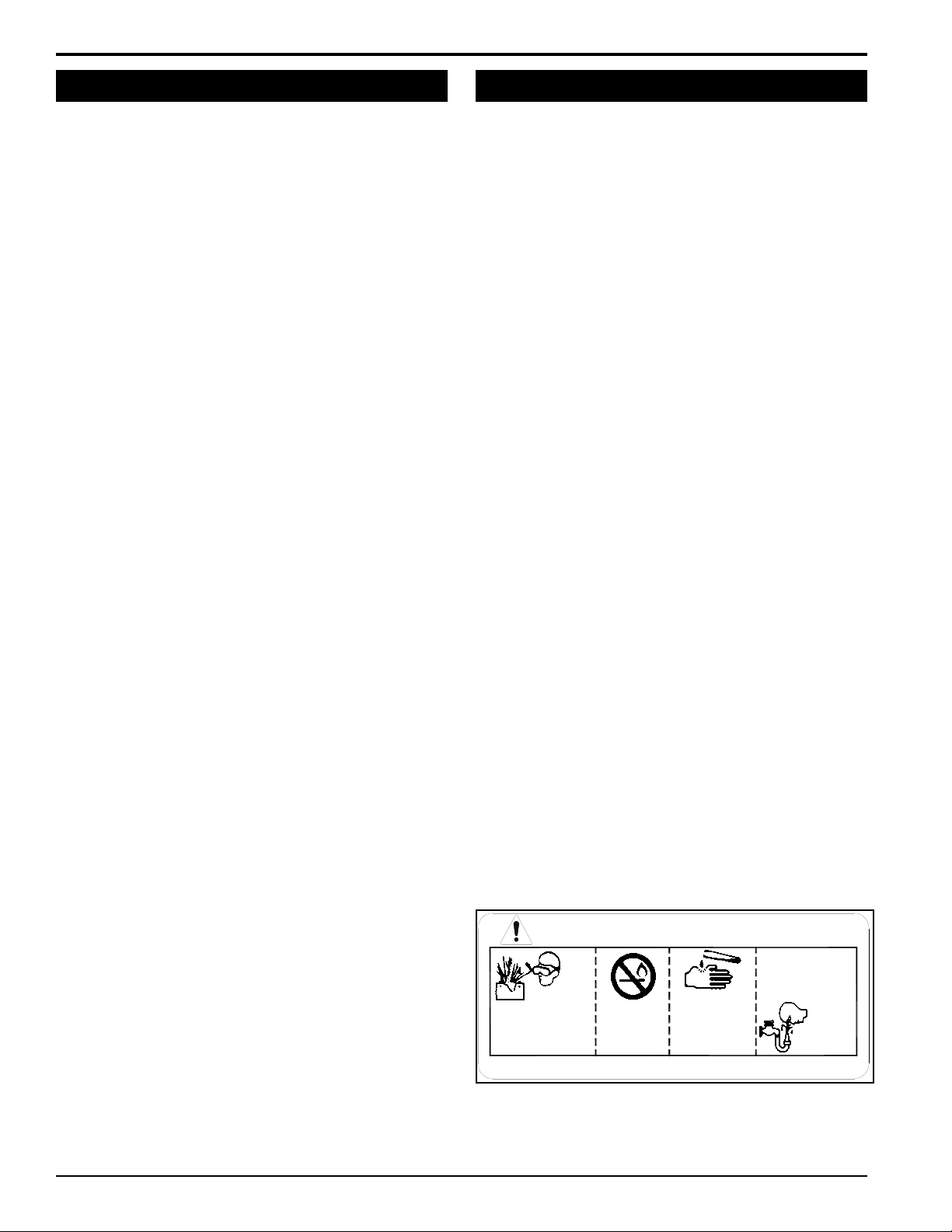
DANGER / POISON
SHIELD EYES
EXPLOSIVE GASES
CAN CAUSE
BLINDNESS OR
INJURY
NO
• SPARKS
• FLAMES
• SMOKING
SULFURIC
ACID
CAN CAUSE
BLINDNESS OR
SEVERE BURNS
FLUSH EYES
IMMEDIATELY
WITH WATER
GET
MEDICAL
HELP
FAST
KEEP OUT OF THE REACH OF CHILDREN. DO NOT TIP. KEEP VENT CAPS TIGHT AND LEVEL.
1.8 TOWING SAFETY
Rotate the discharge tube to face the same direction of the
1.
towing vehicle before towing.
Insert transport safety pin and clip, and set turntable brake
2.
handle to locked position.
Connect hitch safety chains. Tighten and secure trailer hitch
3.
bolts. Do not attempt to tow the trailer if the vehicle is not
equipped with a 2” ball.
Do not exceed maximum towing speed, indicated on tire
4.
sidewall. Inflate tires to manufacturers specifications as
stated on the tire sidewall.
Optimum towing performance can be achieved by maintain
5.
ing a horizontal trailer hitch.
Check wheel lug bolts periodically to ensure they are tight
6.
and secure.
Make sure the jack stand and the rear stabilizer on trailer
7.
are in the UP position during towing.
Never allow passengers to ride on the chipper.
8.
If applicable, shut off fuel supply when towing.
9.
1.9 BATTERY SAFETY
Improper use and care of the battery on electric start models
1.
can result in serious personal injury or property damage.
Always observe the following safety precautions.
Poison/Danger - Causes Severe Burns. The battery contains
2.
sulfuric acid. Avoid contact with skin, eyes or clothing. Keep
out of reach of children.
ANTIDOTE-External Contact: Flush immediately with
lots of water.
ANTIDOTE-Internal: Drink large quantities of water
or milk. Follow with milk of magnesia, beaten egg or
-
3.
4.
5.
6.
7.
vegetable oil. Call a physician immediately.
ANTIDOTE-Eye Contact: Flush with water for 15 min
utes. Get prompt medical attention.
The battery produces explosive gases. Keep sparks, flame
or cigarettes away. Ventilate area when charging battery.
Always wear safety goggles when working near battery.
The battery contains toxic materials. Do not damage bat
tery case. If case is broken or damaged, avoid contact with
battery contents.
Neutralize acid spills with a baking soda and water solution.
Properly dispose of a damaged or worn-out battery. Check
with local authorities for proper disposal methods.
Do not short circuit battery. Severe fumes and fire can
result.
Before working with electrical wires or components, disconnect battery ground (negative) cable first. Disconnect posi
tive cable second. Reverse this order when reconnecting
battery cables.
-
-
-
6
Page 9
SAFETY
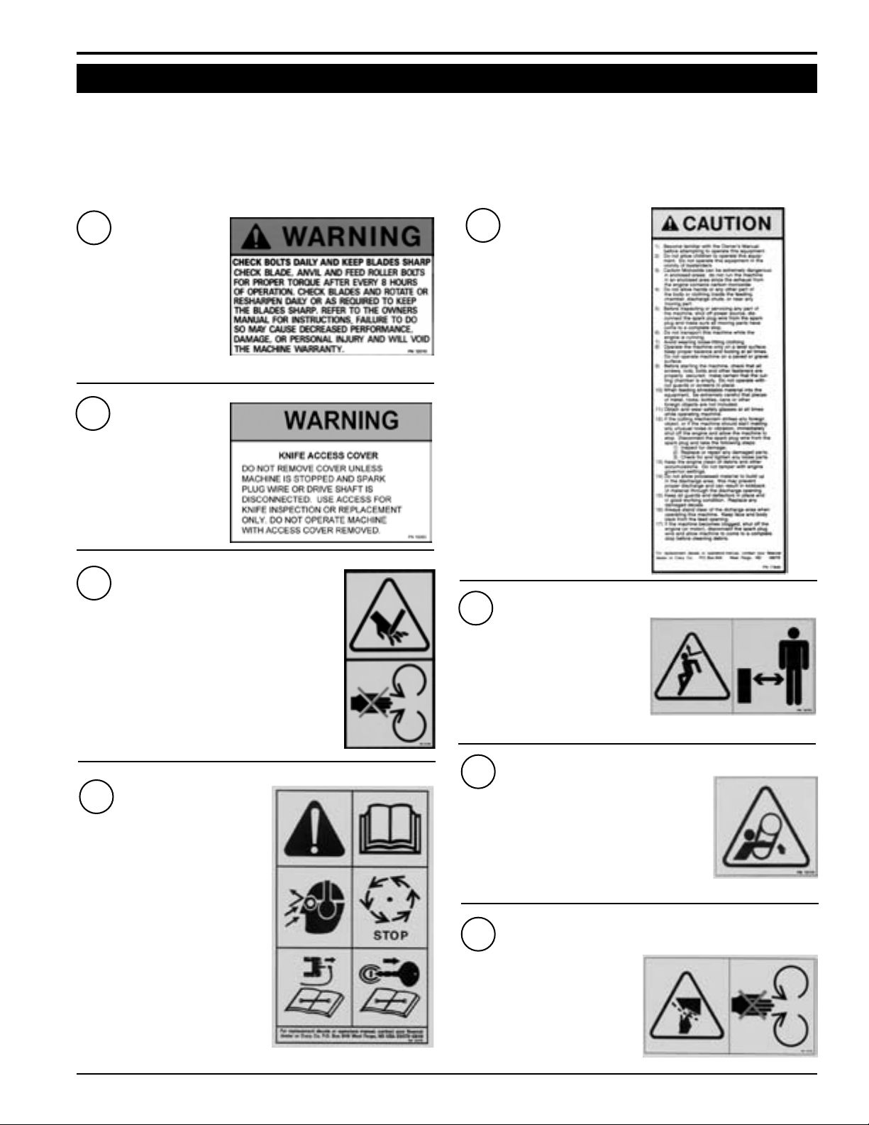
1.10 SAFETY DECALS
See Section 1.11 for decal locations. Familiarize yourself with all of the safety and operating decals on the machine
and the associated hazards. See the engine owners manual or contact the engine manufacturer for engine safety instructions and decals. Make certain that all safety and operational decals on this machine are kept clean and in good
condition. The decals are shown below at reduced sizes. Refer to the parts catalog if you need a replacement decal.
Decals that need replacement must be applied to their original locations.
PN 12010
1
MODEL 74624S ONLY
2
PN 16085
MODEL 74624S ONLY
PN 12169
2
MODEL 74628S ONLY
KEEP HANDS AND FEET OUT OF INLET AND
DISCHARGE OPENINGS WHILE MACHINE IS OPERATING TO AVOID SERIOUS PERSONAL INJURY. STOP
AND ALLOW MACHINE TO COME TO A COMPLETE
STOP BEFORE CLEARING OBSTRUCTIONS.
3
PN 17846
MODEL 74624S ONLY
PN 12173
4
DO NOT OPERATE THIS EQUIPMENT
IN THE VICINITY OF BYSTANDERS.
DO NOT ALLOW CHILDREN TO OPERATE THIS EQUIPMENT. ALWAYS
STAND CLEAR OF DISCHARGE AREA
WHEN OPERATING THIS MACHINE.
KEEP FACE AND BODY AWAY FROM
DISCHARGE AREAS.
PN 12172
3
MODEL 74628S ONLY
READ AND UNDERSTAND THIS OWNER/OPERATORS MANUAL. BE COMPLETELY FAMILIAR WITH THE CONTROLS AND THE PROPER USE OF
THIS EQUIPMENT
OBTAIN AND WEAR SAFETY GLASS
ES AND USE HEARING PROTECTION
AT ALL TIMES WHEN OPERATING
THIS MACHINE.
BEFORE INSPECTING OR SERVICING
ANY PART OF THIS MACHINE, SHUT
OFF POWER SOURCE, DISCONNECT
SPARK PLUG WIRE FROM SPARK
PLUG AND MAKE SURE ALL MOVING
PARTS HAVE COME TO A COMPLETE
STOP.
PN 12174
5
MODEL 74628S ONLY
DO NOT OPERATE MACHINE WITHOUT SHIELDS IN
PLACE. FAILURE TO DO SO MAY CAUSE SERIOUS
INJURY OR DEATH.
-
KEEP HANDS AND FEET OUT OF
INLET AND DISCHARGE OPENINGS
WHILE MACHINE IS OPERATING
TO AVOID SERIOUS PERSONAL INJURY. STOP AND ALLOW MACHINE
TO COME TO A COMPLETE STOP
BEFORE CLEARING OBSTRUCTIONS.
6
PN 12175
7
Page 10
SAFETY
DANGER
FLYING DEBRIS FROM DISCHARGE
PN 16558
KEEP CLEAR OF DISCHARGE AT ALL TIMES.
POINT DISCHARGE AT AREA FREE OF
BYSTANDERS OR ANYTHING THAT COULD BE
DAMAGED BY FLYING DEBRIS. DO NOT
CLEAN OR ADJUST MACHINE UNLESS ENGINE
AND ROTOR HAVE COME TO A COMPLETE
STOP. DO NOT OPERATE WITHOUT ALL
GUARDS IN PLACE.
CAUTION
TO OPERATE AUTO FEED:
TO ACTIVATE THE AUTO FEED SYSTEM.
TURN SWITCH TO "ON" POSTITION.
TO ACTIVATE THE MANUAL FEED SYSTEM.
TURN SWITCH TO "OFF" POSTITION.
WHEN USING THE AUTO FEED SYSTEM,
RUN ENGINE AT FULL SPEED, FEED MATERIAL
INTO CHIPPER AND STAND CLEAR. CHIPPER
WILL AUTOMATICALLY START AND STOP THE
FEED ROLLER.
REFER TO OPERATION AND MAINTENANCE
MANUAL FOR ADDITIONAL INSTRUCTION.
PN 12737
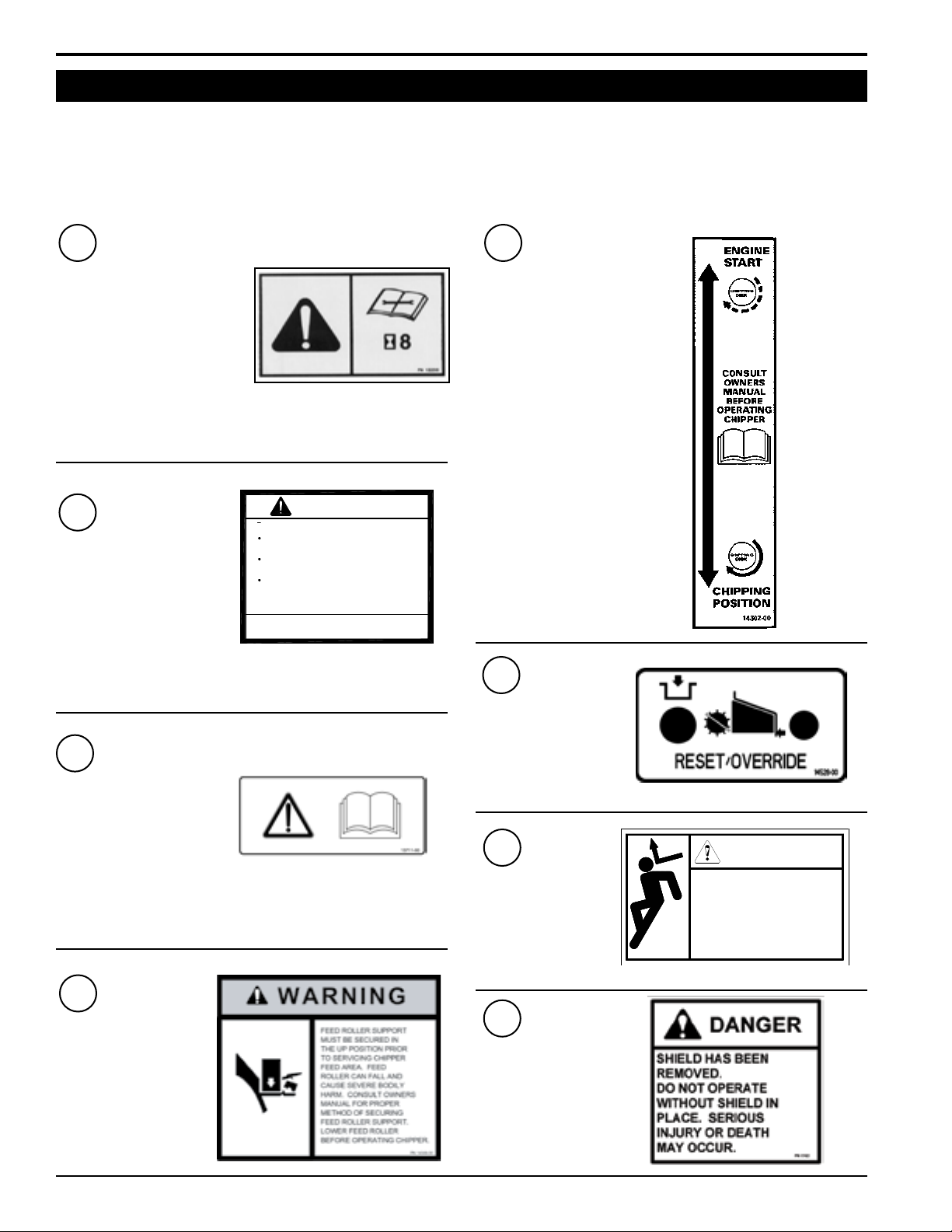
1.10 SAFETY DECALS (CON'T)
See Section 1.11 for decal locations. Familiarize yourself with all of the safety and operating decals on the machine
and the associated hazards. See the engine owners manual or contact the engine manufacturer for engine safety instructions and decals. Make certain that all safety and operational decals on this machine are kept clean and in good
condition. The decals are shown below at reduced sizes. Refer to the parts catalog if you need a replacement decal.
Decals that need replacement must be applied to their original locations.
PN 12250
7
MODEL 74628S ONLY
CHECK BLADE BOLTS FOR PROPER TORQUE AFTER EVERY 8
HOURS OF OPERATION. CHECK
BLADES AND ROTATE OR RE
SHARPEN DAILY OR AS REQUIRED
TO KEEP BLADES SHARP. RE
FER TO OWNERS MANUAL FOR
INSTRUCTIONS. FAILURE TO DO
SO MAY CAUSE POOR PERFOR
MANCE, DAMAGE OR PERSONAL
INJURY AND WILL VOID THE MA
CHINE WARRANTY.
PN 12737
8
MODEL 74628S ONLY
PN 14302-00
11
-
-
-
-
12
PN 14528-00
PN 13711-00
9
MODEL 74628S ONLY
READ AND UNDERSTAND THIS
OWNER/OPERATORS MANUAL.
BE COMPLETELY FAMILIAR
WITH THE CONTROLS AND THE
PROPER USE OF THIS EQUIPMENT.
10
PN 14049-00
8
13
14
PN 16558
PN 17423
MODEL 74624S ONLY
Page 11

SAFETY
2
5 *
10
14 *
6
4
13
* Decals 5 and 14 are
located underneath
the access cover
7
1
3
11
8
9
12
1.11 SAFETY DECAL LOCATIONS
The numbers below correspond to the decals in Section 1.10. Familiarize yourself with all of the safety and operational
decals on the machine and the associated hazards. See the engine owners manual or contact the engine manufacturer for engine safety instructions and decals. Make certain that all safety and operating decals on this machine are kept
clean and in good condition. Refer to the parts catalog if you need a replacement decal. Decals that need replacement
must be applied to their original locations.
9
Page 12

2
Section
ASSEMBLY
WARNING
Before inspecting or servicing any part of this machine, shut
off power source, disengage the hydraulics, remove ignition key and make sure all moving parts have come to a
complete stop.
2.1 ATTACH TRAILER WHEELS
Remove the chipper from its shipping crate. Place the
1.
unit on a level surface before attempting to assemble
it. See the torque chart in the back of the manual for
tightening torque of bolts and screws.
Raise the trailer several inches from the ground with a
2.
hoist or jack. Support the chipper securely.
Lift one wheel to a hub and align the wheel lug holes
3.
with the hub lug bolts.
Thread the lug nuts (found in the parts kit) onto wheel
4.
studs and tighten the lug nuts to 75 ft.-lbs. Follow a
star pattern when tightening the lug nuts.
Repeat this step for the remaining wheel.
5.
2.2 ATTACH DISCHARGE CHUTE
1. The chute rotator is connected to the chipper frame rst
with two 3/8 bolts from the owners kit. Install but do not
tighten. Remove the top cover from the chute rotator to
expose the rotator drive sprocket.
2. Attach the discharge chute to the mounting ange on
the chipper frame. The square discharge chute will t
over the round section of the chipper frame.
3. Place the discharge ring, and discharge retainer around
the base of the mounting ange on the chipper frame.
4. Attach the discharge ring and retainer to the ange with
the provided 3/8” x 1-1/4” bolts and nuts. Tighten to
proper torque.
5. Install the chain around the discharge ring and sprocket
on the inside of the chute rotator. Connect chain with
the connector link.
6. Reassemble the top cover and tighten the 4 bolts.
7. Slide the chute rotator assembly back to remove chain
slack and tighten the two attachment bolts.
8. Torque all fasteners to proper values.
IMPORTANT
If any bolts or nuts are dropped in the machine, be sure to
remove them before starting the machine. Remove items
from the shredder area by removing the discharge screen.
10
Page 13

ASSEMBLY
2.3 ATTACH TRAILER HITCH
1.
Attach the ball coupler to the hitch weldment using
the provided 1/2” x 4” bolts and 1/2” washers and 1/2”
nuts. Tighten to proper torque.
Slide the hitch weldment into the hole in the frame,
2.
back to the 1/2” mounting holes.
Connect the hitch weldment to the frame using the two
3.
1/2” x 4-1/2” bolts, 1/2” washers and 1/2” nuts. Tighten
to proper torque.
2.4 REAR STABILIZER
The rear stabilizer is installed by sliding the stabilizer into
the corresponding slot on the rear of the chipper frame.
The stabilizer is secured and adjusted with the provided
snap pin.
2.6 CHECKING/ADDING HYDRAULIC FLUID
Hydraulic uid drives the feed roller. The hydraulic pump
is direct or belt driven from the engine or disk rotor.
The hydraulic pump requires premium hydraulic uids
containing high quality rust, oxidation, and foam inhibitors. These include premium turbine oils, API CD engine
oils per SAE J183, M2C33F or G automatic transmission
uids meeting Allison C-3 or Caterpillar TO-2, and certain
specialty agricultural tractor uids.
If system has no oil, follow this startup procedure:
Clean all system components (reservoir, fittings, etc.)
1.
before starting the hydraulic pump.
2.
After filtering the hydraulic fluid, fill the hydraulic res
ervoir.
Fill the inlet line leading from the reservoir to the pump
3.
before start-up. Loosen the fitting at the pump on this
inlet line until oil bleeds out.
Start the engine and run at the lowest possible RPM.
4.
As you purge air from the unit, the oil level in the res-
5.
ervoir will drop and bubbles may appear in the fluid.
Refill the reservoir as necessary.
Run the feed roller in both directions for several min-
6.
utes until any remaining air purges from the unit. Refill
the reservoir as necessary.
Shut down the engine, check for and correct any fluid
7.
leaks, and check the reservoir level. Add fluid if necessary. The hydraulic pump is now ready for operation.
-
2.5 CHECK BATTERY
The chipper is shipped with a battery. The battery is
connected to the battery cables using the two 1/4” bolts
and nuts found in the parts kit. To connect:
Route the battery cables to the proper battery terminals,
1.
hooking positive to positive, and negative to negative.
Connect cables with 1/4” bolt and nuts. Tighten nuts
2.
to proper torque.
Check battery for proper fluid level and fill if neces-
3.
sary.
If necessary, charge battery.
4.
2.7 ADDING MOTOR OIL TO ENGINE
The machine was shipped with oil in the engine, as it
1.
was tested at the factory.
To determine which type of oil to use, refer to the
2.
engine owners manual included in the owners kit of
the chipper.
Remove the oil fill plug.
3.
Checking as necessary, add oil to the motor until the
4.
dipstick shows the correct reading.
2.8 CHECK COOLANT (DIESEL ONLY)
You may need to add coolant before you start the diesel
engine. See engine owner's manual.
11
Page 14

9. Chipper
Chute
8. Extension
Tray
10. Reset Button
15. Rear
Stabilizer
14. Bottle Jack
12. Fuel
Gauge
11. Fuel Tank
13. Discharge
Chute Rotor
6. Feed Roller
Engagement
7. Safety Bar
1. Chipper
Engagement
4. Tongue Jack
5. Discharge Cap Crank
3. Control
Panel
2. Control
Switch
3
FEATURES & CONTROLS
Section
Understanding how your machine works will help you achieve the best results when using your chipper. The following
descriptions dene the features and controls of your machine.
REFER TO ENGINE OWNERS MANUAL FOR FURTHER ENGINE OPERATING INSTRUCTIONS.
12
Page 15

FEATURES & CONTROLS
3.1 DESCRIPTION OF FEATURES
1. CHIPPER ENGAGEMENT: To activate, slowly push the
handle toward the ground. To disengage the machine,
move the handle back up to the original position.
2. CONTROL SWITCH: Turn switch off to bypass hydrau-
lic feed control and run the chipper manually.
3. CONTROL PANEL: The control panel is described
in Sec. 3.2.
4. TONGUE JACK: Use to adjust the height of the
hitch.
5. DISCHARGE CAP CRANK: Rotate to direct the discharge of material vertically.
6. FEED ROLLER ENGAGEMENT: Move the control
arm to engage the feed roller The cycle of the control
arm, forward to back, is R, F, N, R.
7. SAFETY BAR: Activate the safety bar in case of an
emergency by pushing it. When the safety bar is activiated, the chipper stops operating. To resume operation,
push the reset button.
8. EXTENSION TRAY: Holds chipping materials before
they are pulled into the feed roller and chipped.
3.2 DESCRIPTION OF CONTROL PANELS
Diesel control panel
9. CHIPPER CHUTE: Feed materials into the chipper
chute.
10. RESET BUTTON: When the safety bar is activated,
the chipper stops operating. To resume operation, push
the reset button.
11. FUEL TANK: Remove cap to fill tank.
12. FUEL GAUGE: Shows remaining fuel
13. DISCHARGE CHUTE ROTOR: Crank to direct the
discharge of chipped material horizontally.
14. BOTTLE JACK: Use to lift the feed roller up if it becomes
plugged with chipping material.
15. REAR STABILIZER: Prevents the chipper from tipping
when it is disconnected from the towing vehicle.
Gas control panel
KEY: For gas engines, turn the key to the right to activate the
electric start. On diesel models, turn the key to the left to
activate the glow plug. When the glow plug extinguishes,
turn the key to the right to start. DO NOT START THE
MACHINE WITH THE CHIPPER ENGAGED.
THROTTLE: This controls the speed of the engine. On diesel
models, turn the throttle counterclockwise to increase
the speed and turn it clockwise to decrease it. For gas
models, raise the throttle lever to increase the speed
and lower it to decrease.
CHOKE: Push the choke up to start a cold gasoline engine.
Decrease choke as the engine warms.
MURPHY SWITCH: See starting instructions for diesel
engines. The murphy switch prevents the engine from
running with low oil pressure, or high engine temperature. To start the engine, hold the switch until the oil
pressure appears on the gauge.
13
Page 16

4
OPERATION
Section
As with any other piece of outdoor power equipment, getting the feel for how your machine operates and getting to
know the best techniques for particular jobs are important
to overall good performance.
The chipping operation takes place on the front of the ma
chine, where hardened steel chipper blades are mounted
on a rotating disk assembly. Material fed into the chipper
chute is sliced into small chips and propelled out through
a discharge tube.
4.1 FILLING THE TANK
Purchase fuel in small quantities and store in clean, approved containers. A container with a capacity of 2 gallons or less with a pouring spout is recommended. Such a
container is easier to handle and helps eliminate spillage
during refueling. DO NOT MIX OIL WITH GASOLINE.
Gasoline Alcohol blends
Gasohol (up to 10% ethyl alcohol, 90% unleaded gasoline
by volume) is approved as a fuel for Honda engines. Other
gasoline/alcohol blends are not approved.
WARNING
Before operating your machine, be sure you read and
understand all safety, controls and operating instruc-
tions in this Owner/Operator's manual and on your
machine. Failure to follow these instructions can re-
sult in serious injury or property damage.
WARNING
Gasoline is highly ammable and its vapors are explosive. To prevent personal injury or property damage:
Store gasoline only in approved containers, in well
ventilated, unoccupied buildings, away from sparks or
ames. Do not ll the fuel tank while the engine is hot
or running, since spilled fuel could ignite if it comes in
contact with hot parts or sparks from ignition. Do not
start the engine near spilled fuel. Never use gasoline
as a cleaning agent.
Gasoline Ether blends
Methyl Tertiary Butyl Ether (MTBE) and unleaded gasoline
blends (up to a maximum of 15% MTBE by volume) are
approved as a fuel for Honda engines. Other gasoline/ether
blends are not approved.
Diesel Fuel
For best results, use only clean, fresh #2 diesel. Use an
additive for cold weather to prevent the fuel from turning
into a gel.
To Add Fuel:
Stop engine and wait for all parts to stop moving. Re-
1.
move key from key switch.
Allow the engine and muffler to cool for at least three
2.
minutes.
Clean area around fuel fill cap and remove cap.
3.
Using a clean funnel, fill fuel tank to 1/2-inch below
4.
bottom of filler neck to provide space for any fuel
expansion.
Install fuel fill cap securely and wipe up any spilled
5.
fuel.
14
Page 17

OPERATION
4.2 STARTING A GASOLINE CHIPPER
Make sure the cutting chamber is empty before starting.
1.
Reference the Honda Owners Manual.
Check engine oil level before starting. Do not overfill
2.
or underfill oil. The Honda engine is equipped with an
oil level sensor and will not allow the engine to start
in either condition.
Make sure the chipper engagement lever is in the
3.
start position.
Engage the choke if necessary.
4.
Adjust throttle to start/idle position.
5.
6.
Turn the key to the right to engage the starter.
Release the key after the engine starts.
7.
For a Cold Engine — Gradually return the choke from
8.
the choke position to the run position as the engine
warms up.
4.3 STARTING A DIESEL CHIPPER
Make sure the cutting chamber is empty before starting.
Reference the Kubota Owners Manual.
1.
Before starting, fill engine with oil to the correct level.
2.
See engine manual for additional starting, operation
and maintenance instructions. Some oil usage is normal. Check level before each use.
Make sure the chipper engagement lever is in the
3.
start position.
Turn key switch to preheat position (to the left). Hold
4.
in preheat position for several seconds until glow plug
indicator light switches off.
Place throttle control in the idle position.
5.
Push in and hold the Murphy switch push-button. Con-
6.
tinue to hold Murphy switch in when cranking engine
until engine is running.
Activate the starter. Release the switch as soon as
7.
the engine starts. Do not crank over for more than 10
seconds. After engine is running; hold murphy switch
until engine has oil pressure.
WARNING
Allow the machine to come to complete stop before
inspection or servicing.
NOTE
Move machine to a clear level area. Do not operate in
the vicinity of bystanders.
WARNING
Handle fuel with care. It is highly ammable. Always use
an approved container and ll tank outdoors.
CAUTION
Move machine to a clear, level area. Do not operate
in the vicinity of bystanders.
NOTE
The Murphy switch system will shut the engine off if the
oil pressure is too low or if the engine temperature is
too high. If the engine will not run or shuts off for these
reasons, consult your local dealer.
15
Page 18

OPERATION
4.4 CHIPPING
WARNING
Please read and follow all safety instructions in
this manual. Failure to operate the chipper in
accordance with the safety instructions MAY RESULT
IN PERSONAL INJURY!
The Bear Cat chipper is designed to chip a variety of
materials into a more readily decomposing or handled
condition. The following guidelines can be used to help
you get started.
Be sure the unit is at full operating speed before you
1.
start to chip material. Adjust engine speed with the
throttle. On diesel models the throttle can be locked.
Engage the hydraulic feed by moving the control
2.
arm. Pull the arm toward you to engage the hydraulic
feed. The speed of the feed roller can be adjusted by
turning the speed control knob on the chipper valve
assembly.
Select limbs that are up to 6 inches in diameter. Trim
3.
side branches that cannot be bent enough to feed into
the chipper chute. Small diameter branches can be
held together in a bundle and fed in simultaneously.
Place limb, butt end first, into the chipper chute until it
4.
contacts the hydraulic feed roller and is drawn into the
chipper blades. The actual feed rate of the limb into
the chipper will depend on the type of material fed, and
sharpness of the cutting blades.
Feed brush from the side of the chute, rather than from
5.
the front. Step aside to avoid being hit by the brush
moving into the chipper.
Never lean over the chute to push objects into the cut-
6.
ting device. Use a push stick or brush paddle.
Never use shovels or forks to push brush. They can
7.
go through the chipper and cause major damage. In
addition, metal pieces can come back like shrapnel to
injure or kill.
Never push brush into the chute with your feet.
8.
If the feed roller slips downward pressure on the roller
9.
can be increased by moving the eyebolt that connects
the spring to the feed roller.
10.
Alternate greener material with dry material to lubricate
the chipping blades for longer life and better performance. When the chipping blades become dull, they
will require periodic sharpening. Refer to Service and
Maintenance, “Sharpening Chipper Blades.”
WARNING
Obtain and wear safety glasses at all times when
operating the machine. Do not wear loose tting clothing. Use common sense and practice safety to protect
yourself from branches, sharp objects and other harmful objects.
4.5 DIRECTING THE CHIPPER CHUTE
The chipper chute can be locked in 53 different positions
using the chute rotor. The discharge cap can be directed
to adjust how high and how far the chipped material is
blown.
To adjust the chute rotor, lift up the rotor lock. Turn the
chute rotor until the chute faces the desired position. Let
go of the rotor lock and ne tune the position of the rotor
until the lock snaps in place.
The discharge cap is adjusted by turning the discharge
crank cap either clockwise or counterclockwise. Turning
the handle clockwise will raise the position of the discharge
cap. Turning the handle counterclockwise will lower the
position of the discharge cap.
16
Directing the chute
Page 19

OPERATION
4.6 HYDRAULIC FEED CONTROL
The Bear Cat chipper is equipped with a pre-programmed
hydraulic feed control located under the control panel. The
controller monitors chipper rotor RPM, controls the feed
roller, and provides routine maintenance alerts.
The controller can be turned off with the switch located below
the control panel. If the controller becomes damaged, the
chipper will still run with the controller shut off, however all
of the controller functions will be disabled. The feed roller
will have to be controlled with the control arm.
THE FEED CONTROL FUNCTIONS ARE FURTHER
DETAILED BELOW:
1.
The controller monitors the RPM of the chipper rotor. If
the RPM drops below the preset range, the feed roller
is stopped. When the RPM are back up to an acceptable level, the feed roller is reengaged.
The controller also has a “try again” feature. The
2.
controller monitors the hydraulic pressure of the feed
roller. If it senses the level is too high (the feed roller
becomes obstructed) the controller will reverse the feed
roller , removing the material trying to be chipped. The
controller will then engage the roller into the forward
position and try to feed the material again. If this cycle
continues, the obstruction will have to be removed
manually, trimmed, and/or repositioned.
To disable the try again feature, disconnect the 2-pin
3.
connector going to the pressure switch. It is located
above the feed roller motor on the SA-1987 assembly.
4.
The controller will also flash service alerts when it is
started. Every 15 hours it will flash 5 times to indicate
the chipper blades should be sharpened. Every 100
hours it will flash 10 times to indicate the engine oil
should be changed.
4.7 SAFETY BAR OPERATION
There is an orange safety bar located around the extension
tray that will stop the chipper when pushed in. When the
safety bar has been activated, a red light signals the reset
button should be pushed before the feed roller will function.
When you are ready to resume chipping, push the reset
button that is on top of the chipper chute.
If false trips occur from a limb, the reset button can be held
in to override the system. Upon start up, safety bar light
will be on and will require the reset button to be pushed in
before the feed roller will operate.
Safety bar and reset button
NOTE: The RPM sensor on the rotor must be ashing or
the controller won’t work. Clearance between the sensor
and the bolt must be between 1/32” and 3/32”.
To lock the safety bar into travel position, place the exten
sion tray in an upright position. Pushing the safety bar down
will lock the safety bar. To unlock, lower the extension tray
and push in on the safety bar. This will release the ange
and allow the safety bar to move freely.
Flange lock
17
-
Page 20

OPERATION
4.8 FEED ROLLER BOTTLE JACK
The feed roller bottle jack is used to raise the feed roller if
chipping material becomes wedged in the feed roller. The
jack will raise the feed roller and remove the tension on
the chipped material.
WARNING
ALLOW THE MACHINE TO COME TO COMPLETE
STOP BEFORE USING THE BOTTLE JACK.
TO RAISE THE FEED ROLLER:
Turn the check valve clockwise to engage the pump
1.
of the jack.
Once the jack is engaged, pump the handle to raise
2.
the jack.
Secure the position with the safety pin.
3.
Once feed roller is cleared of materials, remove the
4.
safety pin.
Turn the check valve counterclockwise to disengage
5.
the pump and lower the jack.
4.9 STOPPING
Move throttle to slowest position.
1.
Move chipper engagement to the engine start posi-
2.
tion.
Let machine idle for a few seconds.
3.
Turn key to off position.
4.
Allow machine to come to a complete stop.
5.
WARNING
Allow the machine to come to complete stop before
inspection or servicing.
18
Bottle jack
The safety pin secures the bottle jack
Page 21

5
SERVICE & MAINTENANCE
Section
5.1 MAINTENANCE SCHEDULE
The items listed in the service and maintenance schedule are to be checked, and if necessary, corrective action taken. This schedule is designed for units operating under normal conditions. If the unit is operating in adverse or severe usage conditions it may be
necessary for the items to be checked and serviced more frequently.
SEE ENGINE OWNERS MANUAL FOR FURTHER ENGINE MAINTENANCE AND TROUBLESHOOTING INFORMATION.
SERVICE AND MAINTENANCE SCHEDULE
FREQUENCY
COMPONENT
AIR CLEANER CHECK AND CLEAN (1)
AIR INTAKE CLEAN (1)
MAINTENANCE
REQUIRED
REFER TO
ENGINE
OPERATOR
MANUAL
EVERY 8
HOURS
EVERY
25
HOURS
EVERY
50
HOURS
EVERY
200
HOURS
EVERY
YEAR
ENGINE OIL CHANGE (1)
FUEL FILTER REPLACE
SPARK PLUG
ENGINE OIL CHECK
FUEL TANK FILL
CHIPPER ANVIL
CHIPPER BLADES
ALL INTERNAL AND
EXTERNAL NUTS AND
BOLTS
BELT CONDITION CHECK
BELT TENSION CHECK
GREASE ZERKS
ENTIRE MACHINE CLEAN
HYD. OIL FILTER REPLACE
WHEEL BEARINGS CHECK AND REPACK
(1) PERFORM MORE FREQUENTLY UNDER EXTREMELY DUSTY CONDITIONS.
(2) PERFORM MORE FREQUENTLY WHEN CHIPPING DRY OR DIRTY WOOD.
As the Chipper Limited Warranty states, failure by the Owner to perform normal maintenance will void the machine's
warranty. The aggressive, high-speed nature of chipping REQUIRES THE OWNER TO PERFORM THE ABOVE LISTED
NORMAL MAINTENANCE. Special consideration to maintain and re-torque the CHIPPER ANVIL, CHIPPER BLADES,
AND ALL INTERNAL AND EXTERNAL NUTS AND BOLTS is the sole responsibility of the Owner. Failure by the Owner
to do so shall be cause for Bear Cat to deny warranty.
CHECK CONDITION AND
GAP
CHECK 1/16" TO 1/8" CLEAR
ANCE AND RE-TORQUE TO
120 FT- LBS. (2)
CHECK SHARPNESS AND
RE-TORQUE TO 120 FT-LBS.
(2)
RE-TORQUE PER ASSEMBLY
TORQUE CHART
LUBE
-
19
Page 22

SERVICE & MAINTENANCE
Inner blade
access cover
Access
cover
Access
bolts
Sharpened
Surface
Sharpened Surface
Mounting Surface:
Do Not Grind
Mounting Surface:
Do Not Grind
.38
45°
WARNING
DISENGAGE THE HYDRAULICS, OPEN SHIELD AND MAKE SURE ALL MOVING PARTS HAVE COME TO A COMPLETE STOP.
BEFORE INSPECTING OR SERVICING ANY PART OF THIS MACHINE, SHUT OFF POWER SOURCE,
5.2 REMOVING CHIPPER BLADES
The chipper blades will eventually become dull, making
chipping difcult. It is recommended that the chipper blades
are sharpened every 5-15 hours of chipper operation. To
remove the chipping blades for sharpening, use the following procedure:
Remove the two 3/8 inch retaining bolts holding access
1.
cover to main frame assembly.
Tilt access cover over to allow rotor access. The chip
2.
per will not operate when the cover is open. Rotate
the rotor so that the bolts holding the blades are most
accessible. To remove the inner blade, open the access cover located on the top of the feed roller.
Remove the two allen head bolts holding the blade itself.
3.
Repeat for all four blades. The four chipping blades have
two edges per blade and can be reversed one time
each before sharpening. If one side has not been used,
remove and reverse the chipping blades. Tighten bolts
to proper torque and secure access cover.
5.3 SHARPENING CHIPPER BLADES
Depending on the type of wood fed into the chipper, the
blades will eventually dull, making if difcult to feed material
and produce chips. It is recommended that the blades be
checked for sharpness every 8 hours.
Regrind the angled edge of the chipping blades to 45
degrees (refer to gure below). The blades can be ground
on a bench grinder or by a professional. Make sure some
-
type of xture is used to correctly hold the blade at the
proper angle. Be careful when grinding so that the blade
does not become overheated and change color (this will
remove the heat-treated properties). Use short grinding
times and cool with water or some type of liquid coolant.
Try to remove an equal amount off of each blade to maintain
rotor balance.
Never sharpen or back grind the at side of the chipping
blade. This will cause the edge to roll and the chipper blade
will be damaged, resulting in poor chipping performance.
Small imperfections such as nicks, burrs, etc. on the at
side of the blade will not affect the chipping performance
of the machine.
The chipping blades are sharp!! Use care when work-
ing on the machine to avoid injury.
WARNING
When completed, replace the chipping blades and tighten
the bolts to 120 ft-lbs. Install all safety screens and guards
and resume chipping.
20
Page 23

SERVICE & MAINTENANCE
WARNING
DISENGAGE THE HYDRAULICS, OPEN SHIELD AND MAKE SURE ALL MOVING PARTS HAVE COME TO A COMPLETE STOP.
BEFORE INSPECTING OR SERVICING ANY PART OF THIS MACHINE, SHUT OFF POWER SOURCE,
5.4 REPLACING CHIPPER DRIVE BELT
The condition of the drive belt should be checked annually,
or after every 25 hours of operation. If the belt is cracked,
worn, frayed, or stretched, replace it. Only replace it with the
original banded belt type, do not use singe belt types.
To replace the belt:
1.
Remove idler pulley. The pulley is removed by loosen
ing the 1/2” mounting hardware.
Lift belt idler pulley off the idler arm weldment.
2.
Remove the drive belt from the pulleys and take the
3.
old belt out of the machine.
Install new belt on pulleys and lower belt idler. Check
4.
alignment of pulleys and adjust if needed.
Reinstall the belt idler pulley to the idler arm weldment
5.
using the 1/2” hardware. Tighten bolt to proper
torque.
Check belt tension before start-up. If necessary adjust
6.
spring tension
-
Idler pulley
Removing the belt
21
Page 24

SERVICE & MAINTENANCE
WARNING
DISENGAGE THE HYDRAULICS, OPEN SHIELD AND MAKE SURE ALL MOVING PARTS HAVE COME TO A COMPLETE STOP.
BEFORE INSPECTING OR SERVICING ANY PART OF THIS MACHINE, SHUT OFF POWER SOURCE,
5.5 HYDRAULIC DRIVE BELT (HONDA ONLY)
The condition of the hydraulic drive belt should be checked
annually, or after every 25 hours of operation. Replace the
belt if it is cracked, worn, frayed, or stretched.
To replace:
Loosen the mounting bolts shown in Fig. #20.
1.
Loosen the nut (not shown) on the back side of the
2.
adjusting bolt to relieve tension on the belt. Make
sure that the pump mounting bracket moves and
relieves the belt tension.
Remove drive belt according to instructions on prior
3.
page.
Remove the loosened hydraulic belt from the chip-
4.
per.
Install the new hydraulic belt in the same manner
5.
as the old belt was removed.
Replace the drive belt, according to directions on
6.
prior page.
Install the hydraulic drive belt onto the two pul-
7.
leys.
Tighten the nuts on the adjusting bolt to move the
8.
pump mounting bracket. Stop when the belt is at
the desired tension.
Tighten the mounting bolts on the pump mounting
9.
bracket to the proper torque.
Check pulleys for proper alignment and adjust if
10.
necessary.
Hydraulic pump
22
Page 25

SERVICE & MAINTENANCE
WARNING
DISENGAGE THE HYDRAULICS, OPEN SHIELD AND MAKE SURE ALL MOVING PARTS HAVE COME TO A COMPLETE STOP.
BEFORE INSPECTING OR SERVICING ANY PART OF THIS MACHINE, SHUT OFF POWER SOURCE,
5.6 GREASING
Grease zerks on the chipper should be greased every 50
hours, depending upon conditions. See locations in the
pictures below.
23
Page 26

SERVICE & MAINTENANCE
WARNING
DISENGAGE THE HYDRAULICS, OPEN SHIELD AND MAKE SURE ALL MOVING PARTS HAVE COME TO A COMPLETE STOP.
BEFORE INSPECTING OR SERVICING ANY PART OF THIS MACHINE, SHUT OFF POWER SOURCE,
5.7 CHIPPER ANVIL
The four chipping blades should clear the chipper anvil
by 1/16 inch to 1/8 inch. The chipper anvil is adjustable
and reversible. All four sides of the anvil can be used for
chipping.
To adjust:
1. Lift rotor access cover and expose rotor.
2. Loosen the three 1/2 inch bolts that hold the chipper
anvil to the frame.
3. Measure the amount of clearance between chipping
blade and chipper anvil from inside of housing.
4. Adjust inward or outward to the desired measurement,
using the adjustment nuts provided.
5. Tighten bolts on chipping block to 75 ft. lbs. and resume
operation.
If chipper anvil edge is damaged or worn unevenly, remove
the three bolts holding the anvil and use one of the other
three edges. Replace as necessary
5.8 AIR FILTER (DIESEL SHOWN)
Both the Kubota diesel and the Honda gas engines used
on the 6” chipper have air lters. Refer to the Kubota
and Honda engine manuals, included with your machine,
for specic instructions on replacing and cleaning these
lters.
Diesel Air Filter
5.9 COOLANT (DIESEL)
See your engine owner's manual.
24
Chipper anvil
Page 27

SERVICE & MAINTENANCE
WARNING
DISENGAGE THE HYDRAULICS, OPEN SHIELD AND MAKE SURE ALL MOVING PARTS HAVE COME TO A COMPLETE STOP.
BEFORE INSPECTING OR SERVICING ANY PART OF THIS MACHINE, SHUT OFF POWER SOURCE,
5.10 HYDRAULIC RESERVOIR FLUID
The chippers are tested before shipping. In order to test
the equipment the uid levels are lled. However, check
the uid levels before initial operation and add if necessary.
Always check levels before each use. To check levels look
at the side of the hydraulic oil container and make sure the
uid level falls between the marks. If necessary add oil.
On the Kubota models the hydraulic tank is located next to
the fuel tank. A cutout exists to check the uid level.
Premium hydraulic uids containing high quality rust,
oxidation and foam inhibitors are required. These include
premium turbine oils, API CD engine oils per SAE J183,
M2C33F or G automatic transmission uids meeting Allison
C-3 or Caterpillar TO-2, and certain specialty agricultural
tractor uids.
5.11 HYDRAULIC OIL FILTER
The hydraulic oil lter is located underneath the hydraulic
reservoir. It is recommended that this lter be changed
after the rst 50 hours and every 200 hours thereafter. To
change:
1.
Using an oil filter wrench turn the filter counterclock
wise.
Once the filter becomes loose, turn it out the rest of
2.
the way with your hand.
Properly discard old filter.
3.
Lube the rubber seal on the new filter (P/N 16588) with
4.
clean hydraulic oil.
Install the filter onto the threaded pipe. Turn with your
5.
hand until the filter is finger tight.
Turn, by hand, another 1/2 turn.
6.
Check hydraulic oil level and fill if necessary.
7.
-
Hydraulic reservoir
Hydraulic oil lter
5.12 TRAILER SERVICE TIPS
Check wheel bolt torque every 10 hours of towing
1.
use.
Check air pressure in tires every 10 hours of towing.
2.
Check and repack wheel bearings with grease every
3.
12 months.
When towing, always connect the safety chains. Make
4.
sure trailer hitch bolts are tight and secure.
Check trailer lights.
5.
25
Page 28

PROBLEM POSSIBLE CAUSE CORRECTION
Dull chipping blades. Sharpen or replace.
Drive belts loose or worn. Replace drive belts, or increase spring tension
Too large of branch. Limit branch size.
Solid object jammed in the unit. Check and remove.
Broken or missing chipper blade. Replace blade.
Solid object jammed in the unit. Check and remove obstruction.
Chipper blade loose or damaged. Tighten or replace.
Engine crankshaft is bent or damaged. See Engine Service Dealer.
Loose or missing bolts on unit. Tighten or replace bolts.
Chipped or broken chipper blades. Replace chipped or broken blades.
Bad spark plug. Inspect spark plug and replace if necessary.
Incorrect choke setting. Change choke setting.
Dirty air filter. Clean or replace.
Stale gasoline. Drain gasoline and add fresh fuel.
Dirt or water in fuel tank. Contact engine service dealer.
Gas tank is empty. Fill gas tank.
Spark plug wire is disconnected. Connect loose wire to spark plug.
Spark plug is defective. Replace spark plug.
Gas line is obstructed.
Remove gas line at carburetor and check for
obstruction. Drain gas tank and refill with fresh,
clean gasoline.
Dirty, stale, water-contaminated gas. Drain tank and fill with fresh gasoline.
Flooded engine.
Put throttle control in run position and crank
engine several times to clear out excess gas.
Dirty or plugged air cleaner. Clean air cleaner and replace.
Chipper does not chip. Poor
performance.
Unusual vibration or noise.
Engine won't start or is hard to start.
Engine runs poorly.
6
TROUBLESHOOTING
Section
Before performing any of the corrections in this troubleshooting chart, refer to the appropriate information contained in
this manual for the correct safety precautions and operating or maintenance procedures. Contact your nearest dealer
or the factory for service problems with the machine.
26
Page 29

SAE - 8SAE - 2ASAE - 5
SAE
Grade
and
Head
Markings
BOLT DIAMETER
UNIFIED INCH BOLT TORQUE VALUES
(unless otherwise specified in the manual)
Bolt Torque *
(N.m) (ft - lb) (N.m) (ft - lb) (N.m) (ft - lb)
1/4" 7.5 5.5 12 9 17 12.5
5/16” 15 11 25 18 35 26
3/8” 27 20 44 33 63 46
7/16” 44 32 70 52 100 75
1/2” 67 50 110 80 150 115
9/16” 95 70 155 115 225 160
5/8” 135 100 215 160 300 225
3/4” 240 175 375 280 550 400
7/8” 240 175 625 450 875 650
1” 360 270 925 675 1300 975
1-1/8” 510 375 1150 850 1850 1350
1-1/4” 725 530 1650 1200 2600 1950
1-3/8” 950 700 2150 1550 3400 2550
1-1/2” 1250 930 2850 2100 4550 3350
SAE 2
Bolt
Diameter
"A"
SAE 5
SAE 8
7
SPECIFICATIONS
Section
The tables shown below give correct torque values for various bolts and capscrews. Tighten all bolts to the torques
specied in chart unless otherwise noted. Check tightness of bolts periodically, using this bolt torque chart as a guide.
Fasteners should be replaced with the same grade. Tighten serrated or center-lock nuts to the full torque value.
Do not use these values if a different torque value or tightening procedure is given for a specic application. Torque
values listed are for general use only.
Torque gures indicated at left
are valid for non-greased or
non-oiled threads and heads
unless otherwise specied.
Therefore, do not grease or
oil bolts or capscrews unless
otherwise specified in this
manual. When using locking
elements, increase torque
values by 5%.
ON DISK, BLADE MOUNTING SCREWS
LOCATION ON MACHINE HARDWARE DESCRIPTION
SPECIAL TORQUE REQUIRMENTS
1/2 X 1-3/4” FLHD (ASTMF835) CAP SCREWS
(QTY 8)
* Torque value for bolts
and capscrews are identi-
ed by their head markings.
TORQUE (UNI-
FIED INCH)
120 FT-LBS
27
Page 30

Page 31

Page 32

Crary Industries
237 NW 12th Street, West Fargo, ND 58078-0849
Phone: 701.282.5520 • Toll Free: 800.247.7335
Fax: 701.282.9522 •
E-mail: service@crary.com • opesales@crary.com
www.BearCatProducts.com
 Loading...