

Page 1

5 inch
MADE WITH PRIDE IN THE...
chippers
74520 - 20 HP Hyd
74554 - 540 PTO Hyd
owner's manual
PN: 12666 R1101
Companion to 12665
Page 2

Before You Begin
MANUFACTURED BY CRARY INDUSTRIES
MANUFACTURED IN U.S.A.
XXXXXX
WEST FARGO, NORTH DAKOTA 58078 U.S.A.
SERIAL NUMBER
Dear echo Bear caT cusTomer
Thank you for purchasing an ECHO Bear Cat product. The ECHO Bear Cat line is designed, tested, and manufactured to give years
of dependable performance. To keep your machine operating at peak efciency, it is necessary to adjust it correctly and make regular
inspections. The following pages will assist you in the operation and maintenance of your machine. Please read and understand this
manual before operating your machine.
If you have any questions or comments about this manual, please call us toll-free at 1-800-247-7335.
If you have any questions or problems with your machine, please call or write your local authorized ECHO Bear Cat dealer.
This document is based on information available at the time of its publication. ECHO Bear Cat is continually making improvements
and developing new equipment. In doing so, we reserve the right to make changes or add improvements to our product without
obligation for equipment previously sold.
please senD us Your warranTY carD
A warranty card is included in your owner's kit packaged with your machine. Please take the time to ll in the information requested
on the card. When you send your completed card to us, we will register your machine and start your coverage under our limited
warranty.
parTs orDerinG inFormaTion
For service assistance or parts, contact your nearest authorized
ECHO Bear Cat dealer or the factory. your nearest authorized
dealer will need to know the serial number of your machine to
provide the most efcient service. See below for information on
how to identify and record the serial number for your machine.
if you need engine service or parts:
For engine service pr parts, contact your nearest authorized
engine dealer. an authorized engine dealer can handle all parts,
repairs, and warranty service concerning the engine.
serial numBer locaTion
Please record the serial number in the space provided and on
the warranty and registration card.
replacemenT parTs
Only genuine ECHO Bear Cat replacement parts should be
used to repair the machine. Replacement parts manufactured
by others could present safety hazards, even though they may
t on this machine. Replacement parts are available from your
ECHO Bear Cat dealer.
Provide the following when ordering parts:
The SERIal NuMBER of your machine.
The PaRT NuMBER of the part.
The PaRT dESCRIPTION.
The QuaNTITy needed.
serial numBer
how To conTacT echo Bear caT
address Phone e-mail hours
237 NW 12th Street
P.O. Box 849
West Fargo, Nd 58078
800-247-7335
701-282-5520
Fax: 701-282-9522
opesales@crary.com
service@crary.com
© 2006, CRaRy INduSTRIES, all RIgHTS RESERvEd. PROduCEd aNd PRINTEd IN THE u.S.a.
Monday - Friday,
8 am to 5 pm
Central Time
Page 3

LIMITED WARRANTY
This warranty applies to all AG and Outdoor Power Equipment manufactured by Crary Industries.
Crary Industries warrants to the original owner each new Crary Industries product to be free from defects
in material and workmanship, under normal use and service. The warranty shall extend 1 year from date of
delivery for income producing (commercial) applications and 2 years from date of delivery for non-income
producing (consumer) use of the product. The product is warranted to the original owner as evidenced by a
completed warranty registration on file at Crary Industries. Replacement parts are warranted for (90) days
from date of installation.
ThE WARRANTY REgIsTRATIoN MusT bE coMpLETED AND RETuRNED To cRARY INDusTRIEs
WIThIN 10 DAYs of DELIvERY of ThE pRoDucT To ThE oRIgINAL oWNER oR ThE WARRANTY
WILL bE voID.
In the event of a failure, return the product, at your cost, along with proof of purchase to the selling Crary
Industries dealer. Crary Industries will, at its option, repair or replace any parts found to be defective in material
or workmanship. Warranty on any repairs will not extend beyond the product warranty. Repair or attempted
repair by anyone other than a Crary Industries dealer as well as subsequent failure or damage that may occur
as a result of that work will not be paid under this warranty. Crary Industries does not warrant replacement
components not manufactured or sold by Crary Industries.
This warranty applies only to parts or components that are defective in material or workmanship.
1.
This warranty does not cover normal wear items including but not limited to bearings, belts, pulleys, filters
2.
and chipper knives.
This warranty does not cover normal maintenance, service or adjustments.
3.
This warranty does not cover depreciation or damage due to misuse, negligence, accident or improper
4.
maintenance.
This warranty does not cover damage due to improper setup, installation or adjustment.
5.
This warranty does not cover damage due to unauthorized modifications of the product.
6.
Engines are warranted by the respective engine manufacturer and are not covered by this warranty.
7.
Crary Industries is not liable for any property damage, personal injury or death resulting from the unauthorized
modification or alteration of a Crary product or from the owner’s failure to assemble, install, maintain or operate
the product in accordance with the provisions of the Owner’s manual.
Crary Industries is not liable for indirect, incidental or consequential damages or injuries including but not
limited to loss of crops, loss of profits, rental of substitute equipment or other commercial loss.
This warranty gives you specific legal rights. You may have other rights that may vary from area to area.
Crary Industries makes no warranties, representations or promises, expressed or implied as to the performance
of its products other than those set forth in this warranty. Neither the dealer nor any other person has any
authority to make any representations, warranties or promises on behalf of Crary Industries or to modify the
terms or limitations of this warranty in any way. Crary Industries, at its discretion, may periodically offer limited,
written enhancements to this warranty.
cRARY INDusTRIEs REsERvEs ThE RIghT To chANgE ThE DEsIgN AND/oR spEcIfIcATIoNs
of ITs pRoDucTs AT ANY TIME WIThouT obLIgATIoN To pREvIous puRchAsERs of ITs
pRoDucTs.
Page 4

MANUAL INSERT
PRODUCT: 5” CHIPPERS
MODEL: 74520 & 74554
SUBJECT: PTO LOFA CONTROL REVISION & TORQUE BOLT SPECIFICATIONS
The information for programming the LOFA control (page #16) is incomplete in the manual #12666, revision 11/01. The
programming information for engine models is correct, however the information for the PTO models is not. Refer to the table
below for all correct LOFA control settings.
Also, the chipper blade torque specification was omitted from the Service and Maintenance section of the owners manual
(page #19). When replacing chipper blades (P/N 70739), torque the retaining bolts (P/N 15565) to 20 ft/lbs.
FEED SENSOR PROGRAMMING
MODEL LOW (L) NORMAL (N) HIGH (H) RETURN (RET) POLES (PU)
72520
74554
1650 2000 0 1675 1
1400 1675 0 1425 1
Fig. #1, LOFA control programming
Crary Industries
237 12th St. NW • P.O. Box 849
West Fargo, ND 58078-0849
(701)282-5520 • FAX: (701)282-9522
www.crary.com
Manual Insert
Page 5

Contents
Section Description Page
1.0 SAFETY .................................................................................................................................... 2
1.1 BEFORE OPERATING .......................................................................................................... 2
1.2 OPERATION SAFETY ........................................................................................................... 3
1.3 MAINTENANCE AND STORAGE SAFETY ............................................................................ 4
1.4 PTO SAFETY ........................................................................................................................ 4
1.5 TOWING SAFETY ................................................................................................................. 5
1.6 BATTERY SAFETY ............................................................................................................... 5
1.7 SAFETY DECALS ................................................................................................................. 6
2.0 ASSEMBLY .................................................................................................................................... 7
2.1 ATTACH THE TRAILER AXLE ................................................................................................ 7
2.2 ATTACH THE TRAILER WHEELS .......................................................................................... 7
2.3 ATTACH THE HITCH ............................................................................................................. 8
2.4 ATTACH THE CHIPPER CHUTE ............................................................................................ 8
2.5 ATTACH THE BLOWER DISCHARGE TUBE ......................................................................... 8
2.6 CONNECT HYDRAULIC HARNESS ....................................................................................... 9
2.7 CONNECT PTO SHAFT ......................................................................................................... 9
2.8 ATTACHING CHUTE EXTENSION TRAY ................................................................................ 9
2.9 INSTALLING CHUTE SUPPORT ............................................................................................ 9
2.10 CONNECT HYDRAULIC HARNESS ..................................................................................... 9
2.11 INSTALLING THE TRAILER LIGHTS ..................................................................................... 9
2.12 INSTALLING THE BATTERY .............................................................................................. 10
3.0 CONTROLS .................................................................................................................................. 11
3.1 TOWABLE MODELS ........................................................................................................... 11
3.2 PTO MODELS ..................................................................................................................... 12
4.0 OPERATION .................................................................................................................................. 13
4.1 STARTING (TOWABLE MODEL) ......................................................................................... 13
4.2 STARTING (PTO MODELS) ................................................................................................. 13
4.3 CHIPPING ........................................................................................................................... 13
4.4 HYDRAULIC FEED INSTRUCTIONS .................................................................................... 14
4.5 FEED SENSOR INSTRUCTIONS ......................................................................................... 16
4.6 CHIPPING TIPS ................................................................................................................... 17
4.7 STOPPING (PTO MODELS) ................................................................................................ 17
4.8 STOPPING (TOWABLE MODELS) ...................................................................................... 17
5.0 SERVICE AND MAINTENANCE ................................................................................................................. 18
5.1 SERVICE AND MAINTENANCE SCHEDULE ...................................................................... 18
5.2 SHARPENING CHIPPER BLADES ...................................................................................... 19
5.3 CHIPPING BLADE SHARPENING TIPS .............................................................................. 19
5.4 SETTING CHIPPING BLADE CLEARANCE ......................................................................... 20
5.5 CLEANING PLUGGED ROTOR ........................................................................................... 20
5.6 REPLACING DRIVE BELTS (TOWABLE MODELS) ............................................................ 21
5.7 REPLACING DRIVE BELTS (PTO MODELS) ....................................................................... 21
5.8 REMOVING ROTOR ............................................................................................................ 22
5.9 TRAILER SERVICE TIPS ..................................................................................................... 22
5.10 ADDITIONAL SERVICE AND MAINTENANCE TIPS ........................................................... 22
5.11 GENERAL TROUBLESHOOTING ...................................................................................... 23
6.0 SPECIFICATIONS .................................................................................................................................. 25
6.1 SIZE SPECIFICATIONS ...................................................................................................... 25
6.2 SPECIFICATIONS (74520) .................................................................................................. 26
6.3 SPECIFICATIONS (74554) .................................................................................................. 27
6.4 BOLT TORQUE .................................................................................................................... 28
Page 6
Safety
1
Section
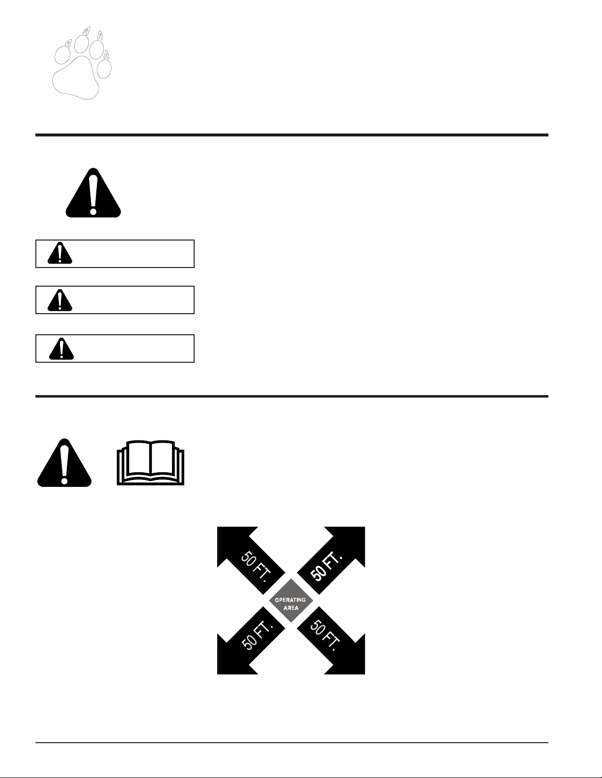
THE SAFETY ALERT SYMBOL
This is the safety alert symbol. It is used in this Owner / Operator’s Manual and on your machine
to alert you to potential hazards.
Whenever you see this symbol, read and obey the safety message that follows it. Failure to obey
the safety message could result in personal injury, death or property damage.
Indicates an imminently hazardous situation that, if not avoided, will result in
DANGER
WARNING
death or serious injury.
Indicates a potentially hazardous situation that, if not avoided, could result in
death or serious injury.
CAUTION
1.1 BEFORE OPERATING
1. Read this Owner / Operator’s
manual. Be completely familiar
with the controls and the proper
use of this equipment.
2. Before inspecting or servicing any
part of the machine, wait for all
parts to stop moving. Be aware that
rotating parts slow down gradually
after power is stopped.
3. Keep safety decals clean and legible. Replace missing or illegible
safety decals.
Indicates a potentially hazardous situation that, if not avoided, may result in
minor or moderate injury.
5. Do not allow children or any person unfamiliar with the use of the
unit to use this machine.
6. Keep the area of operation clear of
all persons, particularly small children. Keep bystanders at least
50 feet (15 meters) away from the
area of operation.
7. Do not run this equipment in an
enclosed area. Do not operate this
equipment in or near buildings,
windows, or air conditioners.
8. If needed, always use an approved
fuel container. Keep open flames,
sparks, smoking materials, and
other sources of combustion away
from fuel.
9. Do not operate this machine if you
are under the influence of alcohol,
medications, or substances that
can affect your vision, balance, and
judgement. Do not operate if tired
or ill. You must be in good health
to operate this machine safely.
4. Familiarize yourself with all of the
safety and operating decals on this
equipment and on any of it’s attachments or accessories.
Page 2
5" Chipper W/Hyd Feed Owners Manual
Page 7
BEFORE OPERATING
10. Use only in daylight or good artifi-
cial light.
11. Wear safety glasses at all times
while operating this machine.
1.2 OPERATION SAFETY
12. Never use without proper guards
in place.
13. Avoid wearing loose fitting clothing. Never operate this machine
wearing clothing with drawstrings
that could wrap around or get
caught in the machine.
14. Check that all screws, nuts, bolts,
and other fasteners are properly secured before starting the machine.
Check all screws, nuts, bolts, and
other fasteners for proper tightness
Safety
to ensure everything is in proper
working condition once every 10
hours of operation.
15. Keep all guards, deflectors, and
shields in place and in good working condition.
16. Do not transport or move machine
while the machine is running.
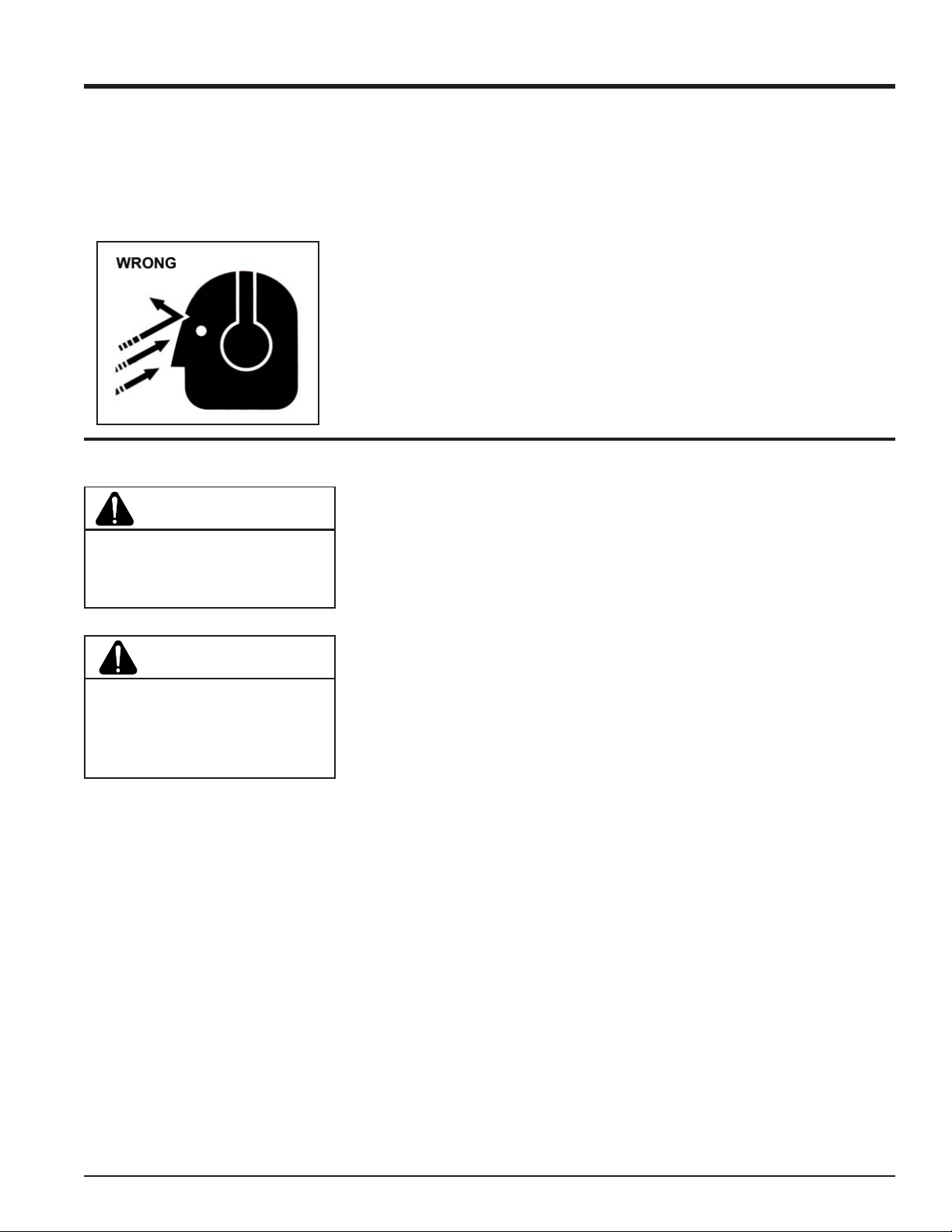
WARNING
Material can kickup or shift suddenly
and cause serious injury or death.
Wear eye and hearing protection.
DANGER
Keep hands, feet and clothing out of
inlets and discharge openings while
machine is operating to avoid serious personal injury.
1. Do not allow hands or any part of
body or clothing near any moving
part.
2. Exclude pieces of metal, rocks,
bottles, cans, and other foreign objects from entering the machine.
3. Shut off machine immediately if the
cutting mechanism strikes any foreign object or the machine starts
making an unusual noise or vibrating. Allow the machine to stop
completely. After machine stops:
A. Inspect for damage.
B. Replace or repair any
damaged parts.
C. Check for and tighten any
loose parts.
4. Stand clear of the discharge area
when operating this machine.
5. Keep your face and body back from
the feed opening.
6. Do not climb on machine when operating. Keep proper balance and
footing at all times.
7. Keep the machine clear of debris
and other accumulations.
8. Set up your work site so you are
not endangering traffic and the public. Take great care to provide adequate warnings.
9. Ensure debris does not blow into
traffic, parked cars, or pedestrians.
10. Check the bolts for correct torque
every 10 hours of operation.
11. Shut off engine and allow machine
to stop completely before clearing
debris if the machine becomes
clogged.
5" Chipper W/Hyd. Feed Owners Manual
Page 3
Page 8
Safety
1.3 MAINTENANCE AND STORAGE SAFETY
NOTE
If equipped, see engine owners
manual or contact the engine manufacturer for engine safety instructions and decals.
1.4 PTO SAFETY
1. Read and follow instructions on
PTO safety decals.
2. Stay alert and pay attention when
PTO is operating.
3. Keep bystanders, especially children, away from PTO driveline.
1. Replace any missing or unreadable safety decals. Refer to the
parts manual for part numbers
when ordering safety decals from
an area Bear Cat dealer.
4. Check the driveline to ensure it is
attached securely to the power
supply.
5. Keep guards and shields in place
at all times while operating. Disengage PTO and shut off engine
before removing guards or shields.
6. Clothing worn by operator must be
fairly tight. Never wear loose fitting jackets, shirts, or pants when
working around the PTO. Tie long
hair back or put under a cap.
2. Store the machine out of reach of
children and where potential fuel
vapors will not reach an open flame
or spark.
3. Allow machine to cool before storing in an enclosure.
7. Keep hydraulic hoses, electric
cords, chains, and other items from
contacting the driveline.
8. Do not exceed the recommended
540 RPM PTO operating speed.
9. When this equipment is stopped
for servicing, inspection, or storage make sure to disengage PTO.
10. Keep hands, feet, and clothing
away from all PTO drive parts.
11. Do not clean, lubricate, or adjust
the PTO shaft when it is running.
Page 4
5" Chipper W/Hyd Feed Owners Manual
Page 9
1.5 TOWING SAFETY
Safety
1. Rotate the discharge tube to face
the opposite direction of the towing vehicle before towing. This prevents the discharge tube from projecting over the trailer wheels and
striking foreign objects.
2. Connect hitch safety chains.
Tighten and secure trailer hitch
bolts. Do not attempt to tow the
trailer if vehicle is not equipped with
a 2” ball.
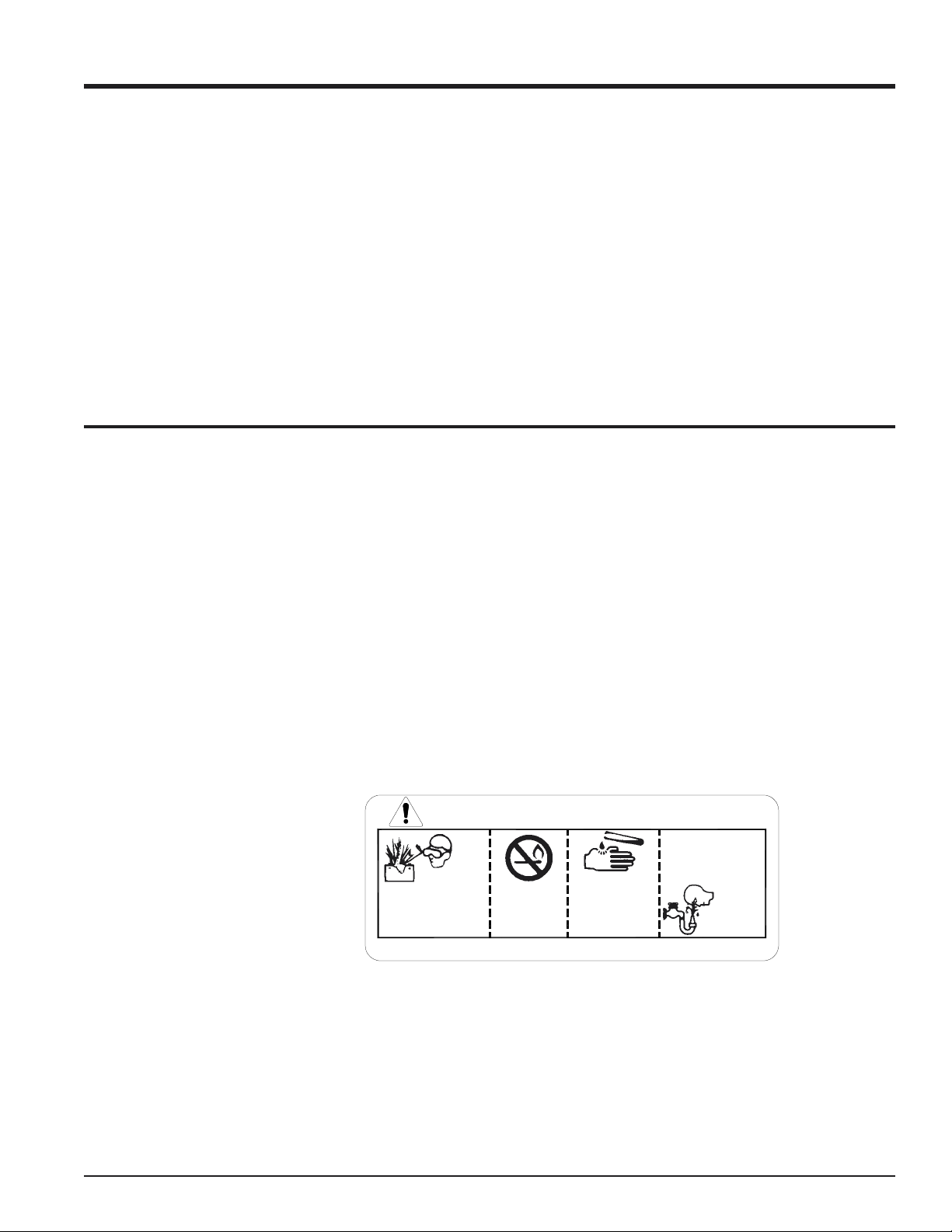
1.6 BATTERY SAFETY
1. Improper use and care of the battery on electric start models can
result in serious personal injury or
property damage. Always observe
the following safety precautions:
A- Poison/Danger - Causes Severe
Burns. The battery contains sulfuric acid. Avoid contact with skin,
eyes or clothing. Keep out of
reach of children.
ANTIDOTE-External Contact:
Flush immediately with lots of water.
ANTIDOTE-Internal: Drink large
quantities of water or milk. Follow
with milk of magnesia, beaten egg
or vegetable oil. Call a physician
immediately.
3. Do not exceed maximum towing
speed, indicated on tire sidewall.
secure it in the DOWN position be-
fore use.
Inflate tires to manufacturers specs
as stated on the tire sidewall.
6. Never allow passengers to ride on
the chipper chute while the vehicle
4. Check wheel lug bolts periodically
to ensure they are tight and se-
is moving, whether the chipper is
running or not.
cure.
7. If applicable, shut off fuel supply
5. Make sure the jack stand on trailer
when towing.
is in the UP position to clear the
ground during towing. Place the
jack stand on a level surface and
ANTIDOTE-Eye Contact: Flush
with water for 15 minutes. Get
prompt medical attention.
Neutralize acid spills with a bak-
ing soda and water solution. Prop-
erly dispose of a damaged or worn-
out battery. Check with local au-
B- The battery produces explosive
gases. Keep sparks, flame or
thorities for proper disposal meth-
ods.
cigarettes away. Ventilate area
when charging battery. Always
wear safety goggles when work-
D- Do not short circuit battery. Se-
vere fumes and fire can result.
ing near battery.
E- Before working with electrical wires
C- The battery contains toxic materi-
als. Do not damage battery case.
If case is broken or damaged,
avoid contact with battery contents.
or components: disconnect bat-
tery ground (negative) cable first.
Disconnect positive cable second.
Reverse this order when reconnect-
ing battery cables.
DANGER / POISON
FLUSH EYES
IMMEDIATELY
SHIELD EYES
EXPLOSIVE GASES
CAN CAUSE
BLINDNESS OR
INJURY
KEEP OUT OF THE REACH OF CHILDREN. DO NOT TIP. KEEP VENT CAPS TIGHT AND LEVEL.
NO
• SPARKS
• FLAMES
• SMOKING
SULFURIC
ACID
CAN CAUSE
BLINDNESS OR
SEVERE BURNS
WITH WATER
GET
MEDICAL
HELP
FAST
5" Chipper W/Hyd. Feed Owners Manual
Page 5
Page 10

Safety Decals
1.7 SAFETY DECALS
Safety and instruction decals are located on the chipper frame and engine. Replace any decal that is damaged or
unreadable.
NOTE
For engine safety and instruction decals, see engine
owners manual or contact engine manufacturer.
5" CHIPPER WITH HYD. FEED DECALS
DECAL # DESCRIPTION
12010 DECAL, CHECK BOLTS
12168 DECAL, 540 PTO DANGER
12169 DECAL, KNIFE ACCESS
12172 DECAL, PROTECTION
12173 DECAL, DISCHARGE
12174 DECAL, SHIELD DANGER
12175 DECAL, INLET AND DISCHARGE
12183 DECAL, CLUTCH ENGAGEMENT
12250 DECAL, CHECK BOLTS
12657 DECAL, MODEL 74520
12658 DECAL, MODEL 74554
12737 DECAL, AUTO FEED
12747 DECAL, FEED POSITION
12748 DECAL, FEED POSITION
12810 DECAL, HITCH LOAD
12811 DECAL 74520 INFO
12812 DECAL, 74554 INFO
16033 DECAL, 540 PTO DANGER
16085 DECAL, ACCESS COVER
16551 DECAL, CLUTCH ENGAGEMENT
16558 DECAL, DISCHARGE
17423 DECAL, SHIELD DANGER
17836 DECAL, BEARCAT PICTURE
17837 DECAL, BLADE DANGER
17846 DECAL, OPERATING INSTRUCTIONS
17913 DECAL- SMALL BEARCAT
13711-00 DECAL, MANUAL BOX
Page 6
5" Chipper W/Hyd Feed Owners Manual
Page 11
Assembly
2
Section
2.0 ASSEMBLY
Your chipper may arrive totally or partially assembled.
Perform the steps in this section if your chipper arrives
partially assembled. Fill the engine with oil (per instructions
in supplied engine manual) and fill the fuel tank with fuel.
2.1 ATTACH THE TRAILER AXLE
1. Remove the chipper from the shipping crate.
2. Place the unit on a level surface before attempting to
assemble it (See Fig. # 3). Refer to the torque chart
in the rear for proper torques.
3. Raise the trailer several inches from the ground with a
hoist or jack. Ensure the chipper is securely supported.
4. Position the fenders over the axle and secure with
eight 3/8 x 1-1/4" bolts and nuts.
5. Align the torsion axle with the mounting brackets on
the sides of the chipper trailer. Secure with four 1/2 x
1-1/4" bolts and nuts.
2.2 ATTACH THE TRAILER WHEELS
1. Hold one wheel to a hub and align the wheel lug holes
with the hub lug bolts (Fig. # 3).
2. Thread the lug bolts into the holes and tighten to 75 ft.
lbs. Follow a star pattern when tightening lug bolts.
3. Repeat for the remaining wheel.
Fig. # 3, Towable model assembly
5" Chipper W/Hyd. Feed Owners Manual
Page 7
Page 12

Assembly
2.3 ATTACH THE HITCH
1. Insert the adjustable hitch into the hitch channel on
the trailer bottom (See Fig. # 3).
2. Insert a 3/8 x 3-1/2" bolt through the bolt hole in the
adjustable hitch.
3. Secure with a washer and nut.
4. Place the jack stand on the side of the hitch and
secure with the snap pin.
2.4 ATTACH THE CHIPPER CHUTE
1. Mount the chipper chute to the chipper housing using
eight 3/8 x 1-1/2" bolts and locknuts (See Fig. # 3 &
4).
2. Attach the chute extension tray to the extension
chute hinge on the chipper. Use four 3/8" x 1" bolts,
washers, and nuts.
2.5 ATTACH THE BLOWER DISCHARGE TUBE
1. Attach the blower discharge tube to the mounting
flange on the chipper frame (See Fig. # 3 & 4). Half of
the mounting clamp is already attached to the tube.
2. Slide the tube into the flange and tighten the bolts to
secure it.
3. Install the second half of the clamp to the tube and
flange.
4. Grease the chute grease zerk to allow free rotation.
Rotate the tube 360 degrees and lock it in place with
the handle to make sure it is mounted correctly.
Page 8
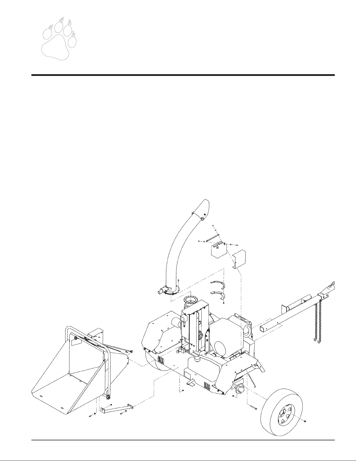
Fig. # 4, PTO chipper assembly
5" Chipper W/Hyd Feed Owners Manual
Page 13

Assembly
2.6 CONNECT HYDRAULIC HARNESS
(TOWABLE MODELS)
1. Connect 6 pin female connect on chipper chute to
male connector on the roller support weldment.
2.7 CONNECT PTO SHAFT
NOTE
When the tractor used has an electric PTO clutch and
brake, a different PTO shaft should be used.
1. Connect the PTO shaft female end to the rotor shaft
using key stock and two set screws contained in the
owners kit (See Fig. # 4).
2. Connect the opposite end of the PTO shaft to the
tractor.
3. Check all screws, bolts, and nuts for tightness. See
torque chart at rear of manual.
2.10 CONNECT HYDRAULIC HARNESS (PTO MODELS)
1. Remove black cover from coils located next to the
engine manifold.
2. Connect one black wire and the green wire with the
black tracer to the coil closest to the hydraulic
control valve.
3. Connect one black wire and the orange wire with a
black tracer to the remaining coil.
4. Route the hydraulic feed harness toward the PTO
hitch. Connect the tractor end of the harness to
switch 12 VDC power supply on the tractor.
2.11 INSTALLING THE TRAILER
LIGHTS
The towable chipper is equipped with tail lights. The lights
must be installed according to the diagram below. Wire
guards and nylon ties are provided for securing the harness
to the chipper.
2.8 ATTACHING CHUTE EXTENSION
TRAY
1. Attach the chute extension tray to the extension
chute hinge on the chipper.
2. Secure with four 3/8" x 1" bolts, washers, and nuts.
2.9 INSTALLING CHUTE SUPPORT
The chute support is connected to the towable chipper by
installing the support with (3) 3/8" X 1-1/4" bolts (P/N 15364).
The bolts are connected with 3/8" nylock nuts, as depicted
in Fig. #3. When all three bolts are installed tighten to
torque.
On the PTO chipper (2) 3/8" bolts hold the support. Insert
the bolts are show in Fig. #4. When the two bolts are inserted,
tighten to torque.
YELLOW
4 PIN CONNECTOR
BROWN
16905
BROWN
GREEN
LH LIGHT
5" Chipper W/Hyd. Feed Owners Manual
RH LIGHT
Fig. # 5
Page 9
Page 14

Assembly
2.12 INSTALLING THE BATTERY
1. The machine may or may not have been shipped with a
battery depending on your area. If you did not receive a
battery with your machine, you will need to purchase
one.
2. Use a battery that meets or exceeds the following specifications:
Battery, Category, Lawn and Garden
BCI Group Size U1
200-250 CCA
7-3/4” X 5-3/16” X 7-5/16”
3. If you received a battery with your machine, proceed to
the next step.
NOTE
The battery that was shipped with the machine was
shipped dry. The battery will need to be serviced
before installation.
6. After filling, battery should be charged to the specifications below and put into service immediately.
Temperature over 60° F:
3 amperes for 4 Hours.
Temperature under 60° F:
3 amperes for 6 Hours.
7. Place charged battery in battery box on chipper shredder.
8. Remove key from engine ignition.
9. Install the positive (+) battery cable to the positive (+)
battery terminal using a 5/16 X 1” hex head bolt and 5/
16 nylock nut. An insulating boot is loosely installed
on this cable. Slide the insulating boot over the terminal, making sure that the terminal is completely covered.
10. Install the negative (-) cable on the negative (-) battery
terminal using a 5/16 X 1” hex head bolt and 5/16 nylock
nut. There is no insulating boot for this terminal.
11. Secure battery box cover.
4. Remove or destroy any sealing device which may have
been used to close or restrict the vent openings.
5. Remove battery vent caps and fill cells until baffle plate
is covered with 1.25” of electrolyte at 80° F. Battery
and electrolyte must at a temperature above 60° F, but
preferably not above 100° F.
WARNING
To avoid sparks and a possible explosion or fire due
to a short circuit:
1. Do not touch the positive (+) battery terminal and
any surrounding metal with tools, jewelry or other
metal objects.
2. When installing battery cables, connect positive
(+) cable first and negative (-) cable last.
IMPORTANT
DO NOT ATTEMPT TO START THE ENGINE AT THIS
TIME. Wait until you have read the complete starting
instructions in the Operation Section of this Manual.
Page 10
5" Chipper W/Hyd Feed Owners Manual
Page 15

Controls
3
Section
3.0 CONTROLS
3.1 TOWABLE MODELS
1. Engine: (See Fig. # 6) Refer to Honda Engine
Operators Manual.
2. Engine Fuel Tank. Use unleaded fuel only. DO NOT
MIX OIL AND GASOLINE.
3. Discharge Lock: Used to pivot the discharge chute.
4. Ball Hitch and Safety Chains: Always use 2" ball
and hook safety chains to towing vehicle.
5. Jack Stand. Always have up and clear from the
ground when moving the unit. When the in use, be
sure jack stand is down and locked in position with
the snap pin.
6. Foot Pedal: Used to engage rotor drive belt. Pressing the pedal releases tension on the drive belt.
6. Hydraulic Feed Control: Engages and disengages
the feed roller.
Fig. #6, Towable Chipper Shredder
5" Chipper W/Hyd. Feed Owners Manual
Page 11
Page 16

Controls
3.2 PTO MODELS
1. 3 pt. Hitch Connections: Mount chipper/shredder to
tractor (Fig. # 7). Connect direct for categories 0 & 1.
A bushing kit must be installed on 3 pt. connections
for category 2 hitches.
2. PTO Shaft: Connects tractor PTO to chipper/
shredder drive shaft. Avoid angle greater than 15
degrees up or down when unit is in use.
3. Leg Stands: Adjustable to allow proper driveshaft
angle. Do not move machine unless the legs clear the
ground.
4. Discharge Lock: Used to pivot the discharge chute.
5. Hydraulic Feed Control: Engages and disengages
the feed roller.
Page 12
Fig. #7, PTO Chipper Shredder
5" Chipper W/Hyd Feed Owners Manual
Page 17

Operation
4
Section
4.0 OPERATION
4.1 STARTING (TOWABLE MODEL)
Move machine to a clear, level area outdoors before starting.
Do not operate machine on a paved, concrete, or gravel
surface. Do not operate in the vicinity of bystanders. Make
sure cutting chamber is empty before starting.
1. Before starting, check engine oil level and fill if necessary. See engine owners manual for operation and maintenance instructions.
2. Before starting, fill fuel tank with fresh, clean unleaded
regular gasoline. DO NOT MIX OIL WITH GASOLINE.
3. Disengage clutch lever by pressing foot clutch pedal.
4. Place engine throttle lever at 3/4 - full open position.
Place engine choke lever to choke position.
5. Activate the starter switch. Release the key as soon
as the engine starts. Do not crank for more than 10
seconds. Repeat if necessary.
6. Move choke lever to run position after engine starts.
Some choke may be needed until engine is fully
warmed up.
7. Once engine is running and no choke is needed,
slowly let foot clutch pedal up. This will engage the
drive belt and the rotor will turn.
4.2 STARTING (PTO MODELS)
1. Place tractor transmission in neutral and set parking
brake.
2 Connect 3 pt. mounts between the chipper and the
tractor. Secure connections with snap pins. Adjust 3
pt. top link so the chipper sits level.
3. Connect PTO shaft to tractor. Make sure you are
using the correct RPM machine.
4. Start tractor engine and engage PTO drive clutch
(refer to tractor owners manual). Increase speed to
rated PTO RPM position.
Note: Do not inspect or work on PTO drive area
without first disengaging PTO and shutting off tractor
engine.
4.3 CHIPPING
WARNING
Due to the aggressiveness of the machines chipping
capacity, do not attempt to hold on to material
intended for chipping once it has been placed in the
chute.
NOTE
If engine kills when engaging foot clutch pedal, either
use more choke or increase engine RPM. When the
clutch is engaged the foot pedal may vibrate or shake
until the engine and rotor have increased to full
operating RPM.
5" Chipper W/Hyd. Feed Owners Manual
1. Select limbs that are between 3/4 and 5 inches in
diameter; trim side branches off that cannot be bent
over enough to fit into the chipper chute. Some small
branches can be broken off on the chipper chute
transport handle. Small diameter branches can be
held together in a bundle and fed in simultaneously.
2. Place limb, butt end first, into the chipper chute until
it contacts the chipping blades. The actual feed rate
of the limb into the chipper will depend on the type of
material being fed, the sharpness of the cutting
blades and the size of the machine. Alternately insert
and retract the limb or insert continuously at a rate
that will not kill the engine. Rotating the branch as it
is being fed will improve cutting action.
3. The chipping blades will dull with use and require
periodic sharpening. Approximate sharpening time is
every 10 hours, or every rental if used commercially.
Refer to the Service and Maintenance section for
instructions.
Page 13
Page 18

Operation
4.4 HYDRAULIC FEED INSTRUCTIONS
4.4.1 FLUIDS
Handle pressurized hydraulic fluid carefully. Escaping
pressurized hydraulic fluid can have sufficient force to
penetrate your skin causing serious injury. This fluid may
also be hot enough to burn. Serious infection or reactions
can develop if proper medical treatment is not
administered immediately.
Premium hydraulic fluids containing high quality rust,
oxidation, and foam inhibitors are required. These include
premium turbine oils, API CD engine oils per SAE J183,
M2C33F or G automatic transmission fluids meeting
Allison C-3 or Caterpillar TO-2. and certain specialty
agricultural tractor fluids.
4.4.2 HYDROSTATIC START UP PROCEDURE
Hydrostatic pressure controlled by the hydraulic control valve,
set at 2500 PSI.
3. Fill the inlet line leading from the reservoir to the
hydraulic pump before start-up. Loosen the fitting on
the pump inlet line until oil bleeds out.
4. Start the engine and run at the lowest possible RPM.
5. The oil level in the reservoir drops and bubbles may
appear in the fluid as air is purged from the unit. Refill
the reservoir as necessary.
6. Run the unit and move the control arm in both
directions for several minutes until any remaining air
is purged from the unit. Refill the reservoir as necessary.
7. Check to ensure the feed roller stops when the
control arm is in the neutral position.
8. Shut down the engine or disengage PTO, check for
and correct any fluid leaks, and check the reservoir
level. Add fluid if necessary.
NOTE
A fitting may need to be loosened and oil-bled to remove air from the system (use same procedures as
steps 3-5).
Follow this start-up procedure to start a new installation or
to restart an installation if the hydrostatic pump was removed
from the system.
1. Make sure all system components (reservoir, fittings,
etc.) are clean before starting the hydrostatic pump.
2. Fill the reservoir with recommended hydraulic fluid.
Filter fluid before filling the reservoir.
Page 14
5" Chipper W/Hyd Feed Owners Manual
Page 19

Operation
4.4.3 CONTROL ARM OPERATION
l. Start the chipper engine or engage the PTO. Bring
the chipper up to operating speed. Refer to and follow
the engine starting, chipper operation, and engine
stopping instructions.
2. Engage the hydraulic feed by moving the control arm.
The control arm has four positions: Reverse, Forward,
Stop, and Reverse.
3. Feed the branch (up to five inches in diameter).
4. Reverse the feed by moving the control arm to either
reverse position if the chipper jams. Remove the
branch and rotate it before reinserting it into the
chute.
5. Adjust the speed of the feed roller with the knob on
the hydraulic control valve.
CONTROL ARM
AUTO FEED
INSTRUCTION DECAL
FEED ROLLER
DIRECTION DECAL
4.4.4 HYDRAULIC FEED MAINTENANCE
CAUTION
Hydraulic systems contain fluid under high pressure.
Never check for leaks with your hands. Relieve pressure
before disconnecting any hydraulic lines.
The hydraulic pump normally does not require regular fluid
changes. The system filter should be changed at 250 hours
or annual intervals. The fluid and filter should be changed
and system cleaned if the fluid becomes contaminated with
foreign matter (water, dirt, grease, etc.) or if the fluid has
been subjected to temperature levels greater than the
maximum recommended.
There is a greaseable bearing on each side of the main
jack shaft on the main hydraulic feed housing. Grease
periodically.
NOTE
Check the reservoir daily for proper fluid level, the
presence of water (noted by a cloudy to milky
appearance, or free water in bottom of reservoir), and
rancid fluid odor (excessive heat).
Fig. #8, Control Arm Operation
5" Chipper W/Hyd. Feed Owners Manual
Page 15
Page 20

Operation
4.5 FEED SENSOR INSTRUCTIONS
The feed sensor monitors the chipper rotor RPM to maximize
chipping efficiency. The low RPM setting is the rotor speed
when the feed roller stops. The feed sensor restarts the
feed roller when the chipper rotor RPM reaches the return
operating speed. This ability to automatically stop the feed
roller prevents the engine from overloading and stalling.
Engine Models: The feed sensor arrives programmed at the
factory to the following recommended settings.
low= 1650 RPM
normal= 2000 RPM
high= 0
return= 1675 RPM
poles= 1
PTO models: Set feed sensor to above recommended factory
settings. Refer to instructions below.
4.5.1 FEED SENSOR OPERATION
The feed sensor is energized when the chipper is started.
Logs begins to feed as the chipper rotor RPM reaches the
"return" setting. The feed sensor continues to monitor the
chipper rotor speed during use.
B. ENTER LOW (L=LOW) RPM
The low setting is the RPM speed where the feed roller stops.
The "up" arrow increases the RPM setting, while the "down"
arrow decreases the RPM setting. Setting the speed lower
causes the engine to lug down more before the feed roller
stops.
1. Hold the appropriate (either up or down) arrow until the
desired RPM speed is displayed.
2. Push the "S" button once with the desired RPM
setting displayed to save.
NOTE: Do not choose a setting equal to or below zero.
C. ENTER NORMAL (N=NORMAL) RPM
The normal setting is the RPM speed the chipper rotor usually
turns.
1. Hold the appropriate (either up or down) arrow until the
desired RPM speed is displayed.
2. Push the "S" button once with the desired RPM
setting displayed to save.
D. ENTER HIGH (H=HIGH) RPM
The high setting is not needed with this application.
1. Set to zero to deactivate.
4.5.2 RESETTING DAILY HOUR
METER
The feed sensor is equipped with an hour meter to track
hour usage. Stop the engine and make sure the chipper
blades and all moving parts are completely stopped before
resetting the hour meter.
1. Turn key switch to "ON" to energize the feed sensor.
2. Push the "S" button until Day flashes on the LCD display.
3. Depress the "S" button for five seconds and release.
4. Push and hold down the "S" button for an additional 13
seconds until daily hours are reset to zero.
The daily hours continue to accumulate until reset by the
operator.
A. INITIATING PROGRAM MODE
1. Hold down the "S" button while turning the engine key to
the "on" position until "L" starts to flash on the LCD.
2. Push the "S" button once with zero displayed to save.
E. ENTER RETURN (RET=RETURN)
RPM
The return setting is the RPM speed where the feed roller
restarts. The feed roller should restart before the rotor reaches
"normal" RPM to maximize chipper efficiency. Setting the
speed higher allows the engine to recover more before the
feed roller restarts.
1. Hold the appropriate (either up or down) arrow until the
desired RPM speed is displayed.
2. Push the "S" button once with the desired RPM
setting displayed to save.
F. ENTER NUMBER OF POLES (IPU =
NUMBER OF POLES)
The number of poles is used to indicate the number of speed
pickup devices.
1. Hold the appropriate (either up or down) arrow until
one (1) is displayed.
Page 16
2. Push the "S" button one with one (1) displayed to
save.
5" Chipper W/Hyd Feed Owners Manual
Page 21

4.6 CHIPPING TIPS
The Bear Cat chipper is designed to chip a variety of
materials into a more readily decomposing or handled
condition. The following guidelines can be used to help you
get started.
1. Run unit at full operating speed before starting to chip
material.
2. Select limbs that are up to 5 inches in diameter.
Trim side branches that cannot be bent enough to
feed into the chipper chute. Hold small diameter
branches together in a bundle and fed in simultaneously.
3. Feed brush from the side of the chipper chute, rather
than from the front. Then, step aside to avoid being
hit by the brush moving into the chipper.
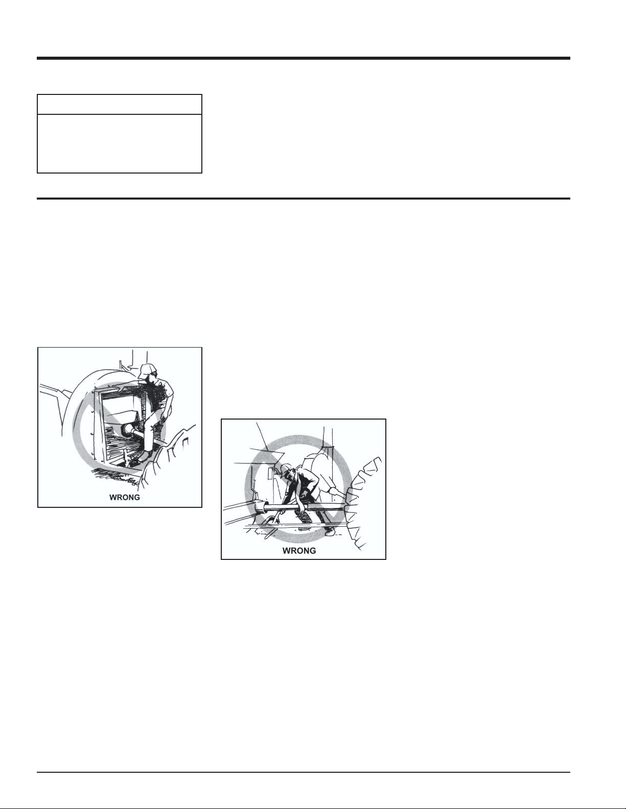
4. Do not lean over the chipper chute to push objects
into the cutting device. Use a push stick or brush
paddle.
5. Never use shovels or forks to push brush. They can
be chipped, are expensive to replace, and cause
extensive damage. In addition, metal pieces can
come back to injure or kill.
6. Never push brush into the chipper chute with your
feet.
Operation
Fig. # 9, Chipping
4.7 STOPPING (PTO MODELS)
To stop the machine, proceed as follows:
1. Move tractor throttle to slow position.
2. Disengage the PTO lever and shut off the tractor
engine.
3. Allow machine to come to a complete stop.
7. Place limb, butt end first, into the chipper chute until
it contacts the hydraulic feed roller and is drawn into
the chipper blades. The actual feed rate of the limb
into the chipper will depend on the type of material
fed and sharpness of the cutting blades.
8. Stop the material feeding and allow the engine to
recover if the engine slows to where it may stall.
9. Remove the branch and rotate it before reinserting it
into the chute if the chipper jams.
10. Alternately insert and retract the limb or insert
continuously at a rate that will not kill the engine.
11. Chipping dead, dry material will create heat and dull
the chipping blades quickly.
12. Alternate greener material with dry material to
lubricate the chipping blades for longer life and better
performance.
13. When the chipping blades become dull, they will
require periodic sharpening. Refer to Service and
Maintenance, "Sharpening Chipper Blades."
4.8 STOPPING (TOWABLE MODELS)
To stop the machine, proceed as follows:
1. Move throttle to slow position.
2. Disengage rotor clutch by pressing foot pedal.
3. Move throttle to stop position or turn off ignition
switch and remove spark plug wire from spark plug.
4. Allow machine to come to a complete stop.
5" Chipper W/Hyd. Feed Owners Manual
Page 17
Page 22

Service & Maintenance
5
Section
WARNING
Before inspecting or repairing any part of the machine,
shut off the engine and make sure all moving parts
have come to a complete stop.
5.0 SERVICE AND MAINTENANCE
5.1 SERVICE AND MAINTENANCE SCHEDULE
SERVICE AND MAINTENANCE SCHEDULE
FREQUENCY
COMPONENT
ENGINE OIL CHECK OIL LEVEL
FUEL TANK FILL
AIR CLEANER CHECK AND CLEAN¹
AIR INTAKE CLEAN¹
NUTS AND BOLTS CHECK
PRE-CLEANER
ELEMENT
ENGINE OIL CHANGE¹
COOLING SHROUDS CLEAN¹
SPARK PLUG
FUEL FILTER REPLACE
CHIPPER BLADES
2-BOLT FLANGE
BEARINGS
BELT TENSIONER
PIVOT
PTO CROSS
JOURNALS
PTO INNER TUBES GREASE
MAINTENANCE
REQUIRED
CLEAN¹
CHECK CONDITION
AND GAP
CHECK, SHARPEN IF
NEEDED³
GREASE
GREASE
GREASE
BEFORE
EACH
USE
•
•
•
•
•
•
EVERY
8
HOURS
•
•
•
EVERY
25
HOURS
•
EVERY
50
HOURS
EVERY
100
HOURS
•
•
EVERY
200
HOURS
•
PTO SHIELD BEARINGS GREASE
•
BATTERY
CONNECTIONS
BELT CONDITION CHECK
BELT TENSION CHECK
DISCHARGE TUBE
FLANGE
TRAILER TIRE
PRESSURE
ENTIRE MACHINE CLEAN
¹ PERFORM MORE FREQUENTLY UNDER EXTREMELY DUSTY CONDITIONS.
³ IT IS A GOOD SIGN THAT YOUR CHIPPER BLADES WILL NEED SHARPENING WHEN MATERIAL STOPS SELF FEEDING.
CHECK
•
•
GREASE
•
CHECK
•
•
EVERY
1500
HOURS
•
•
•
Page 18
5" Chipper W/Hyd Feed Owners Manual
Page 23

Service and Maintenance
5.2 SHARPENING CHIPPER BLADES
WARNING
Before inspecting or servicing any part of the machine,
shut off the engine, and make sure all moving parts
have come to a complete stop. The chipping blades
are sharp! Use care when working on machine to avoid
injury.
The chipper blades will eventually dull, making chipping
difficult. It is recommended to sharpen chipper blades every
5-15 hours of chipper operation.
To remove the chipping blades for sharpening:
1. Remove the one 3/8 inch retaining bolt holding access
cover to main frame assembly.
2. Tilt access cover over to allow rotor access. Rotate
the rotor so that the bolts holding a chipping blade are
most accessible.
3. Remove the two hex head bolts holding the chipper
blade. Repeat for all four chipper blades. The four
chipping blades have two edges per blade and can be
reversed one time each before sharpening. Remove
and reverse the chipping blades if both sides have not
been used. Reinstall chipping blades and proceed
with chipping.
4. If blades need sharpening, grind the angled edge of the
chipping blade to 45 degrees. Grind the blades on a
slow-speed wet grinder if possible, or have them sharpened by a professional. If you use a bench grinder, be
careful when grinding so that the blade material does
not get too hot and change color–this will remove the
blade's special heat treated properties. Use short grinding times and cool with water. Try to remove an equal
amount off each blade to maintain balance. Reinstall.
5.3 CHIPPING BLADE SHARPENING
TIPS
WARNING
Never sharpen the back side of the chipper blade. This
will cause the edge to roll and the chipping blade will
be damaged, causing poor chipping and feeding of
material. Small imperfections, nicks, burrs, etc. on the
flat side of the blade will not affect performance.
Poor chipping performance is usually a result of dull chipping
blades. If your chipper's performance has decreased, check
for the following symptoms:
1. Severe vibration when feeding material into the
chipper.
2. Small diameter branches do not self-feed.
3. Chips discharge unevenly or have stringy tails–
especially when chipping green branches.
Before you sharpen the chipping blades, check for
permanent damage. Replace the blade if:
1. The blade is cracked (especially around the bolt
holes) or the edges are too deeply chipped to be
ground smooth.
2. The base of the cutting edge is worn or has been resharpened so that it is too close to the rotor chipping
slot.
SHARPEN TO
A 45° ANGLE
IMPORTANT
NEVER SHARPEN OR
BACK GRIND THIS SIDE
POOR FEEDING AND
CHIPPING WILL RESULT
.25
45°
Fig. #10, blade sharpening
5" Chipper W/Hyd. Feed Owners Manual
Page 19
Page 24

Service and Maintenance
5.4 SETTING CHIPPING BLADE
CLEARANCE
The chipping blades should clear the chipper block
located directly under the chipper chute by 1/16 inch to
1/8 inch. To adjust the blade clearance, proceed as
follows:
1. Lift rotor access cover and expose rotor. Loosen the
two 1/2 inch bolts that hold the chipper anvil to the
frame.
2. Measure the amount of clearance between chipping
blade and chipper anvil from inside of housing. The
gap should be 1/16" to 1/8".
3. Adjust inward or outward to desired measurement.
Use the nuts on the adjustment bolt for PTO models
(See Fig. # 11).
4. Tighten bolts on chipping block to 75 ft. lbs. and
resume operation.
Remove the two bolts holding the anvil and use one of the
other three edges if the chipper anvil edge is damaged or
worn unevenly. Adjust for correct measurement.
5.5 CLEANING PLUGGED ROTOR
Feeding too much chipable material at once can plug the
chipper. To clear plugged rotor, proceed as follows:
1. On towable models press foot clutch pedal and stop
engine. Release foot clutch pedal when engine is
stopped.
2. Remove the one 3/8" retaining bolt holding the access
cover to the main frame assembly.
3. Lift up rotor access cover.
4. Clean the debris from the chipper rotor. On towable
models, release idler and turn the rotor by hand to be
sure it is free to rotate.
5. Close rotor access cover and replace bolts.
CHIPPER
BLADE
ROTOR
ANVIL
ANVIL
ADJUSTMENT
1/16" - 1/8"
Fig. # 11, Chipper blade and anvil clearance
Page 20
5" Chipper W/Hyd Feed Owners Manual
Page 25

Service and Maintenance
5.6 REPLACING DRIVE BELTS (TOWABLE MODELS)
Check the condition of the drive belt annually or after every
25 hours of operation, whichever comes first. Replace
cracked, frayed, worn, or stretched drive belt. Only
replace drive belt with original banded type belt, do not use
single type belts. To adjust the drive belt, proceed as
follows:
1. Depress foot clutch pedal.
2. Shut engine off.
3. Disconnect battery cables.
4. Remove large belt guard (three 5/16 inch bolts).
5. Adjust the eyebolt that anchors the idler spring to
adjust the belt tension.
6. Tighten the eyebolt until the belt deflection at the
center of the belt is 7/16" when a 20 lb. load is placed
against the belt (See Fig. # 12).
7. Replace belt guard.
8. Start engine and test belt for looseness.
5.7 REPLACING DRIVE BELTS (PTO
MODELS)
1. Remove large belt guard (three 5/16" bolts).
2. Loosen eye bolt.
3. Push belt idler pulley off drive belt.
4. Remove drive belt from pulleys.
5. Install new belt on pulleys and lower belt idler. Check
alignment of pulleys and adjust if needed.
6. Check belt tension before start-up. Adjust the eyebolt
that anchors the idler spring to adjust the belt tension.
Tighten the eyebolt until the belt deflection at the
center of the belt is 7/16" when a 20 lb. load is placed
against the belt (See Fig. # 12). Move the engine on
the mounting stand if unable to attain proper tension.
7. Replace belt guard.
8. Depress foot clutch pedal, start engine, release foot
clutch pedal to engage belt, and test unit.
9. Readjust pulleys and belt tension if needed.
9. Replace the belt if no adjustment is left.
7/16" Deflection
20 lbs
Fig. # 12, Belt tension
5" Chipper W/Hyd. Feed Owners Manual
Page 21
Page 26

Service and Maintenance
5.8 REMOVING ROTOR 5.9 TRAILER SERVICE TIPS
1. Remove the one 3/8 inch retaining bolt holding access
cover to main frame assembly. Tilt access cover over
to allow rotor access.
2. Remove large belt guard (three or five 5/16 inch bolts).
3. Lift belt idler pulley off drive belt and remove belt from
pulleys.
4. Remove the bushing and pulley from the rotor shaft
using the push bolts from the bushing.
5. Remove the two 1/2 inch bolts on each rotor bearing.
6. Pound 1/4" roll pin out of the rotor shaft on front
bearing.
7. Lift the rotor assembly completely out of the frame
with an overhead hoist or lifting device. The complete
rotor assembly is 140 lbs.
8. Remove both bearings with a puller when the rotor
assembly is out of the frame and place new bearings
on rotor shaft.
9. Replace roll pin with a new 1/2" x 2" pin, P/N 15137.
10. Return the complete rotor assembly to the chipper
frame with an overhead hoist or lifting device.
11. Slide rotor back until front roll pin is tight against the
front bearing.
12. Lock the front bearing and install the four 1/2 inch
bolts on each bearing to secure them to the frame.
Tighten bolts to 75 ft. lbs.
1. Check wheel bolt torque every 10 hours of towing use.
2. Check air pressure in tires every 10 hours of towing.
3. Check and repack wheel bearings with grease every 12
months.
4. Connect safety chains when towing.
5. Tighten and secure trailer hitch bolts.
6. Check trailer lights.
5.10 ADDITIONAL SERVICE AND
MAINTENANCE TIPS
1. Service engine according to engine owners manual.
2. Every 10 hours of operation, all bolts and other
fasteners should be checked for correct torque.
3. Remove the discharge screen (all models) daily to
avoid material buildup under normal mounting surfaces. Clean away material and reinstall screen.
4. The chipper has greaseable bearings and pivots that
require grease every 50 hours:
A. Two bearings on the rotor shaft (All models).
B. One grease zerk on the discharge chute (All
models).
C. One pivot on the clutch pedal (Model 74520).
D. Two bearings on the jack shaft (Model 74554).
13. Check and adjust chipper anvil if needed. Lock rear
bearing.
14. Slide bushing onto shaft with flange against bearing
and lock bushing to shaft.
15. Attach large pulley to bushing.
16. Replace drive belt on pulleys and lower belt idler.
Check alignment of pulleys and adjust engine if
needed.
17. Check belt tension before start-up. Adjust the eyebolt
that anchors the idler spring to adjust the belt tension.
Tighten the eyebolt until the belt deflection at the
center of the belt is 7/16" when a 20 lb. load is placed
against the belt (See Fig. #11).
18. Close cover and replace bolts.
19. Replace belt guard and resume operation.
20. Depress foot clutch pedal, start engine, release foot
clutch pedal to engage belt, and test unit. Readjust
pulleys and belt tension if needed.
E. Two bearings on the PTO shaft shield (Model
74554).
F. One grease zerk on the idler pivot (Model 74554).
Page 22
5" Chipper W/Hyd Feed Owners Manual
Page 27

5.11 GENERAL TROUBLESHOOTING
Problem Possible Cause Correction
Improper control settings Use proper setting
Lack of fuel Fill fuel tank
Service and Maintenance
Engine will not start
Engine or rotor stalls or stops
Hard to feed chipper requires
excessive power
Internal problems See dealer
Spark plug disconnected Connect spark plug
Dirty, stale, or contaminated gas Refill tank with fresh gasoline
Obstructed discharge
Improper blade clearance Adjust clearance
Dull chipper blades Sharpen blades
Feeding material too fast into chipper Slow feed rate
Plugged rotor Clear rotor
Dull chipper blades Sharpen blades
Improper blade clearance Adjust clearance
Obstructed discharge
Engaging clutch too fast Lift clutch lever more slowly
Use branch or similar object to clear
discharge
Use branch or similar object to clear
discharge
Engine stalls or belt squeals
with engaging clutch
Material from chipper wraps
around the rotor shaft
Plugged rotor
Belt tension too loose Tighten or replace belt
Stringy, green material bypasses
chipper blades
Improper blade clearance Adjust clearance
Chipper blades to anvil clearance is
incorrect
Dull chipper blades Sharpen or replace blades
5" Chipper W/Hyd. Feed Owners Manual
Clear rotor, feed material into shredder
more evenly
Rotate branch or material when
feeding to cut completely
Set chipper blade to anvil clearance to
recommended distance (1/16" to 1/8")
Page 23
Page 28

Service and Maintenance
5.11 GENERAL TROUBLESHOOTING (CONTINUED)
Drive system vibration
Excessive vibration while
running
Rotor out of balance
Check drive belts and pulleys for bad
or worn areas. Check PTO shaft for
wear.
Inspect rotor for broken or missing
chipper blades. Repair if needed.
Check rotor to see if rotor is
assembled correctly.
Rotor will not turn
Cannot engage clutch
Excessive belt wear
Chipper blade to anvil clearance is
incorrect
Drive belt too loose or broken Adjust or replace
Obstructed discharge
Plugged rotor Clear rotor
Improper belt installation Install belt properly
Shock absorber binding Replace shock absorber
Improper belt tension Tighten or loosen belt as needed
Engagement spring binding in spring
cover
Pulleys not aligned Aligned pulleys with straight edge
Clutch pedal binding Determine cause and repair
Not using correct belt
Pulley damaged or wore Replace pulley
Pulley not in alignment Align pulley with straight edge
Belt tension too loose Tighten belt or replace
Set chipper blade to anvil clearance to
recommended distance (1/16" to 1/8")
Use branch or similar object to clear
discharge
Remove spring cover and clean
Contact authorized dealer to order
Bear Cat belts
Trailer sways during towing Tire air pressure not correct Check tire sidewall for inflation limits
Engine speed too slow Increase engine speed
Plugged discharge tube
Page 24
Feeding material too fast into chipper Slow feed rate
5" Chipper W/Hyd Feed Owners Manual
Page 29

g
g
g
g
g
g
g
Specifications
6
Section
6.0 SPECIFICATIONS
6.1 SIZE SPECIFICATIONS
Specifications
Overall Size 150" x 73" x 90"
Max. Chipper Capacity (Dia.) 5"
Chipper Blade Qty.
Rotor Size 20" Dia. X .125
Rotor Wei
Rotor Shaft Diameter 1.75"
Dischar
Drive Type Belt
Belt Size 2B70
Weight (lbs.)
Wheel Base 62"
Tires 225/75/15
Fuel Tank Capacity (
Hydraulic Tank Capacity
(
En
ht 140 lbs.
e Size 6"
al.) 6.6
al.)
ine
4 Reversible Tool
1490 lbs. (En
900 lbs. (PTO)
Honda OHV 20HP
asoline
Steel
ine)
3
5" Chipper W/Hyd. Feed Owners Manual
Page 25
Page 30

Specifications
6.2 SPECIFICATIONS (74520)
Page 26
5" Chipper W/Hyd Feed Owners Manual
Page 31

6.3 SPECIFICATIONS (74554)
Specifications
5" Chipper W/Hyd. Feed Owners Manual
Page 27
Page 32

Specifications
6.4 BOLT TORQUE
CHECKING BOLT TORQUE:
The tables shown below give correct torque values for various bolts and capscrews. Tighten all bolts to the torques specified
in chart unless otherwise noted. Replace hardware with the same strength bolt.
SAE - 8SAE - 2ASAE - 5
ENGLISH TORQUE
Bolt
Diameter
1/4" 7.5 5.5 9.5 9 17 12.5
5/16"151125183526
3/8" 27 20 44 33 63 46
7/16" 44 32 70 52 100 75
1/2" 67 50 110 80 150 115
9/16" 95 70 155 115 225 160
5/8" 135 100 215 160 300 225
3/4" 240 175 375 280 550 400
7/8" 240 175 625 450 875 650
1" 360 270 925 675 1300 975
1-1/8" 510 375 1150 850 1850 1350
1-1/4" 725 530 1650 1200 2600 1950
SAE 2SAE 5SAE 8
A
Bolt Torque*
METRIC TORQUE SPECIFICATIONS
Bolt
Diameter
M30.50.4-----M432.2-----M554----- M6 6 4.5 11 8.5 17 12 19 14.5
M8 15 11 28 20 40 30 47 35
M102921554080609570
M12 50 37 95 70 140 105 165 120
M14 80 60 150 110 225 165 260 190
M16 125 92 240 175 350 255 400 300
M18 175 125 330 250 475 350 560 410
M20 240 180 475 350 675 500 800 580
M22 330 250 650 475 925 675 1075 800
M24 425 310 825 600 1150 850 1350 1000
M27 625 450 1200 875 1700 1250 2000 1500
4.8 8.8 10.9 12.9
Bolt Torque *
Torque figures indicated above are valid for non-greased or non-oiled threads and heads unless otherwise specified. Therefore, do not grease or
oil bolts or capscrews unless otherwise specified in this manual. When using locking elements, increase torque values by 5%.
* Torque value for bolts and capscrews are identified by their head markings.
Page 28
5" Chipper W/Hyd Feed Owners Manual
Page 33

Page 34

Page 35

Page 36

crary Industries
237 NW 12th Street, West Fargo, Nd 58078-0849
Phone: 701.282.5520 • Toll free: 800.247.7335
fax: 701.282.9522
e-mail: service@crary.com • opesales@crary.com
www.bearcatProducts.com
 Loading...