

Page 1
I
nstruction &
Owners Manual
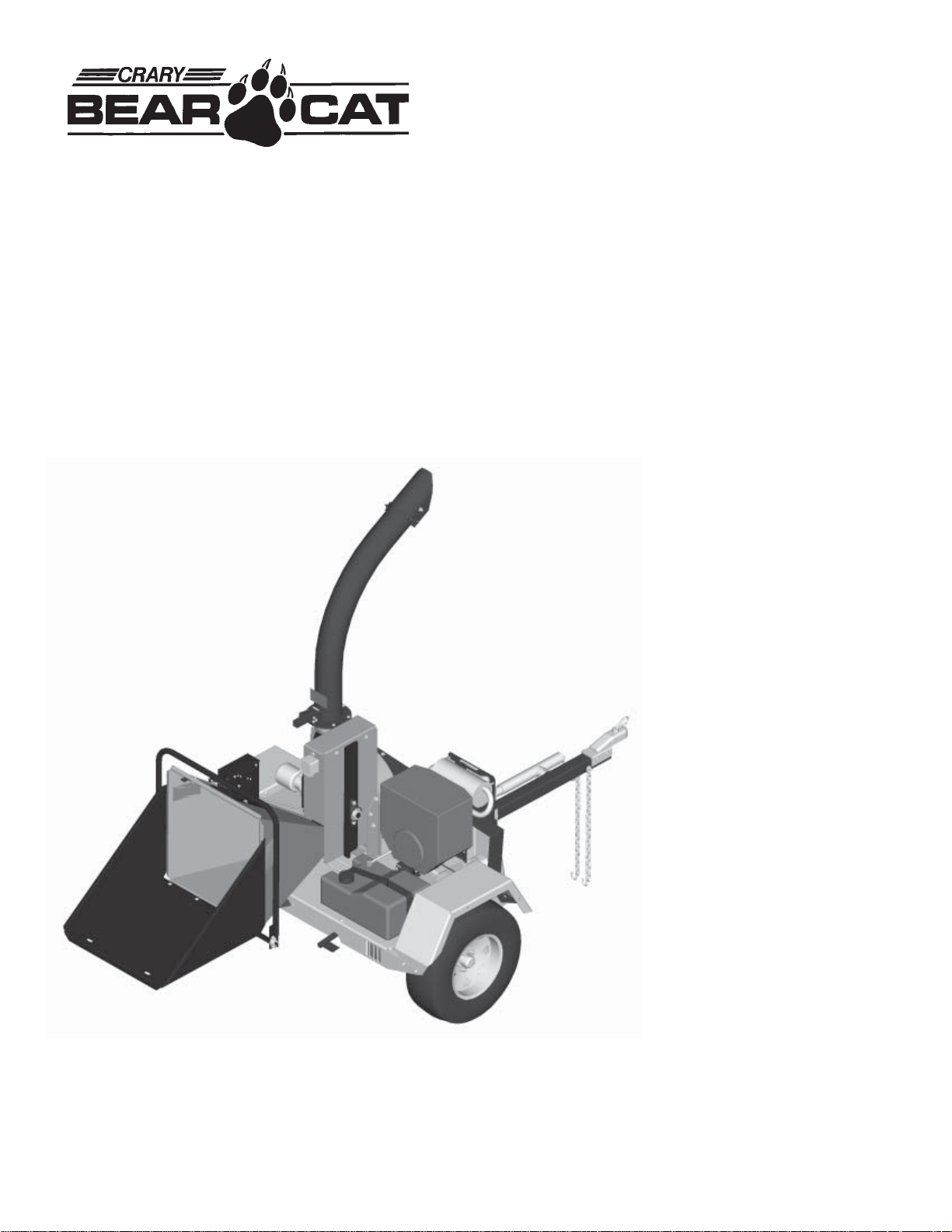
5"Chipper
Models
74520
74554
Crary Company
Box 849
West Fargo, ND 58078
(701) 282-5520
FAX: (701) 282-9522
www.crary.com
• (800) 247-7335
Cat. No. 12666
Manual No. 399
Page 2
Dear Bear Cat Customer,
Thank you for purchasing a Crary Bear Cat Chipper. The Bear Cat
Chipper is designed, tested, and manufactured to give years of
dependable performance. To keep your chipper operating at peak
efficiency, it is necessary to adjust it correctly and make regular
inspections. The following pages will assist you in the operation and
maintenance of your machine. Please read and understand this manual
before operating the chipper.
If you have any questions or comments about this manual, please call us
toll-free at 1-800-247-7335.
If you have any questions or problems with your chipper, please call or
write your local factory-authorized Bear Cat dealer.
Please Send Us Your Warranty Card
A warranty card is included in your owners kit packaged with your
chipper. Please take the time to fill in the information requested on the
card. When you send your completed card to us, we will register your
machine and start your coverage under our limited warranty.
How to Contact
Bear Cat
A
DDRESS
Crary Bear Cat
237 NW 12th Street
PO Box 849
West Fargo, ND 58078
P
HONE
800-247-7335
701-282-5520
Fax: 701-282-9522
E
MAIL
opesales@crary.com
service@crary.com
H
OURS
Owner's Record
Please take a moment to record the
following information about your chipper. If
you need to call for assistance, please be
ready to provide your model and serial
numbers. This information will allow us (or
your dealer) to help you more quickly when
you call.
Model Number
Serial Number
M-F, 8 a.m. to 5 p.m.
Central Time
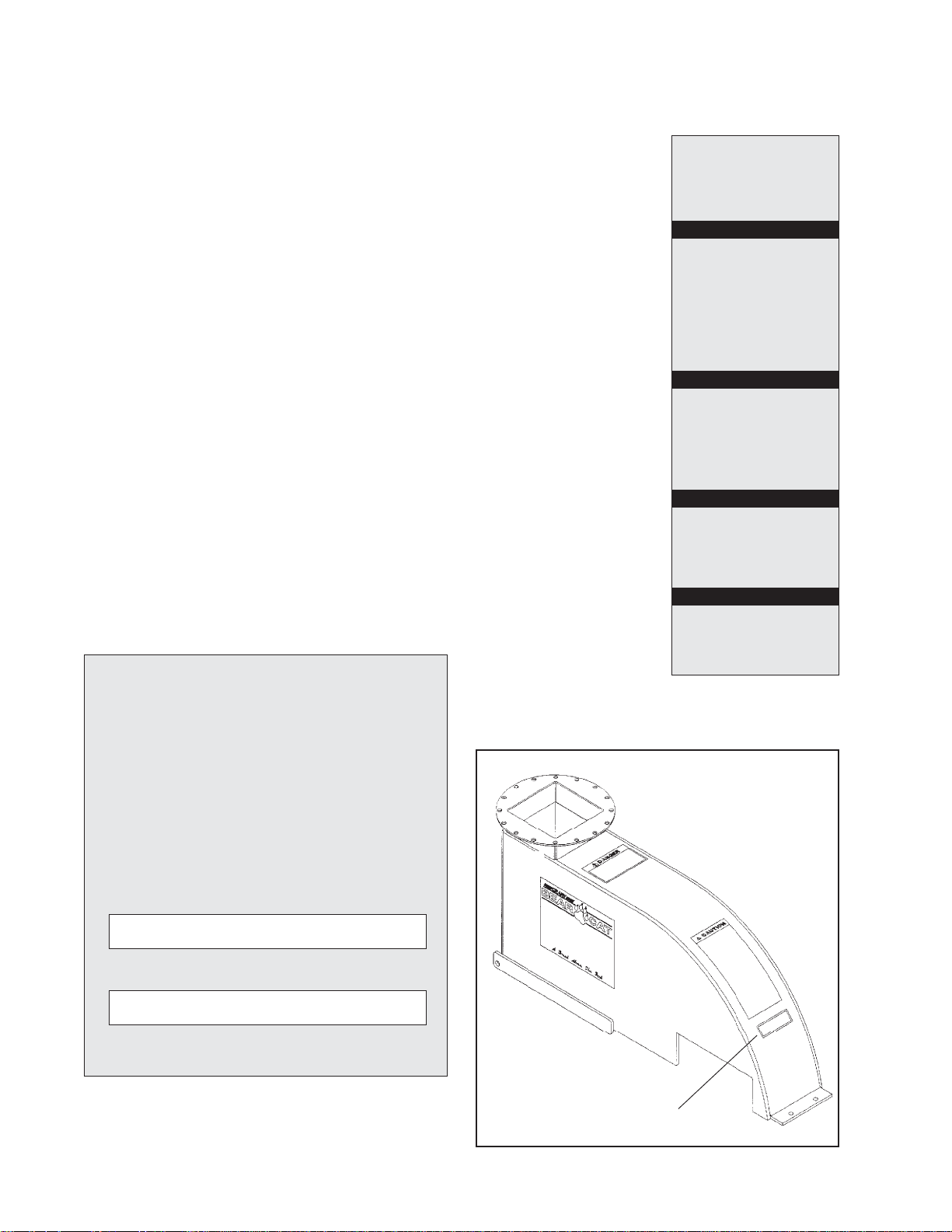
Serial Number Decal Location
Serial Number Decal
Page 3

Chipper Limited Warranty
Crary Bear Cat Chipper models 74520 and 74554 are warranted for two years from date of sale for
consumers and 90 days from the date of sale for commercial or rental operations.
Within the above stated period, Crary Co. will replace any part(s) found to be defective in material and/
or workmanship, after the receipt of the part in our plant. Labor costs to replace these defective parts
will be paid at a Crary established labor rate and time allowed (flat rate) for repair. All transportation
charges incurred in shipping part(s) are the responsibility of the purchaser.
This warranty is void in the case of accidents, failure to perform normal maintenance, or failure to
follow those instructions listed in the service manual. This warranty is also in lieu of all other
expressed warranties and voids any implied warranty as to the merchantability or fitness of the product
for a particular purpose and of any other obligation on the part of Crary Co. Some states do not allow
limitations on how long the implied warranty lasts, so the above limitation may not apply to you.
This warranty applies only to parts or components which are defective, and does not cover necessary
repair due to normal wear, misuse, accidents, or lack of proper maintenance. This includes belts,
pulleys, and chipper blades. Regular routine maintenance of the unit to keep it in proper operating
condition is the responsibility of the owner.
All warranty repair reimbursable under the Crary Co. warranty must be performed by an authorized
Bear Cat service dealer using Bear Cat approved replacement parts. Repair or attempted repair by
anyone other than an authorized Bear Cat service dealer is not reimbursable under the Crary Co.
warranty. In addition, these unauthorized repair attempts may result in additional malfunction, the
correction of which is not covered by warranty.
Crary Co. is not liable for indirect, incidental, or consequential damages in connection with the use of
this product including any cost or expense or providing substitute equipment or service during periods
of malfunction or non-use.
Some states do not allow the exclusion of incidental or consequential damages, so the above exclusion
may not apply to you. This warranty gives you specific legal rights. You may also have other rights
which vary from state to state.
Be sure to note the chipper serial number in any correspondence with Crary Co. or any authorized Bear
Cat dealer. The serial number is located on the chipper trailer.
Warranty
Page 4

Contents
Safety Instructions ........................................................................2
Engine Model Assembly ...............................................................9
PTO Model Assembly..................................................................11
Operation .....................................................................................12
Attach the Trailer Axle ............................................................................. 9
Attach the Trailer Wheels ......................................................................... 9
Attach the Hitch ....................................................................................... 9
Attach the Chute ......................................................................................9
Attach the Blower Discharge Tube ...........................................................9
Connect PTO Shaft................................................................................ 11
Starting: 13 HP Honda ........................................................................... 12
Starting: 20 HP Honda .......................................................................... 12
Starting: PTO Models.............................................................................12
Feed Sensor Instructions ....................................................................... 13
Feed Sensor Programming Instructions ................................................. 14
Chipping................................................................................................. 15
Stopping Instructions: Engine Models .................................................... 16
Stopping Instructions: PTO Models........................................................16
Service and Maintenance ...........................................................17
Sharpening Chipper Blades ....................................................................17
Chipping Blade Sharpening Tips............................................................. 18
Setting Chipping Blade Clearance .......................................................... 18
Adjusting Drive Belt ............................................................................... 19
Replacing Drive Belt............................................................................... 19
Clearing Plugged Rotor........................................................................... 20
Repairing or Replacing Rotor Bearings ................................................... 20
Greaseable Bearings .............................................................................. 21
Trailer Service Tips ................................................................................ 21
Service and Maintenance Schedule ....................................................... 22
Troubleshooting..........................................................................23
Specifications ..............................................................................25
Warranty
1
Page 5
Safety Instructions
Y our safety and the safety of others is important. Valuable safety messages are
provided in this manual and on the machine. Please read these messages carefully .
A safety message alerts to potential hazards that could injure you or others. Each
safety message is preceded by one of three words: DANGER, W ARNING, or
CAUTION.
DANGER
WARNING
CAUTION
Before Operating
You WILL be KILLED or SERIOUSL Y HURT if safety instructions are not
followed.
You CAN be KILLED or SERIOUSL Y HUR T if safety instructions are not
followed.
You CAN be HURT if safety instructions are not followed.
• Do not operate this equipment before reading and understanding the owners
manual. See engine owners manual for additional safety information.
• Keep safety decals clean and legible.
• Replace missing or illegible safety decals.
• Familiarize yourself and other operators with the equipment operation.
Don’t hurry the learning process or take the unit for granted.
• Do not allow children-or any person unfamiliar with the use of the unit- to
use this machine.
• Do not operate this equipment in the vicinity of bystanders. Keep area
clear of all persons and pets.
• Do not run this equipment in an enclosed area; carbon monoxide is
extremely dangerous. The engine exhaust contains carbon monoxide, a
colorless, odorless, and tasteless gas.
• Always use an approved fuel container. Do not remove gas cap or add fuel
when engine is running. Add fuel to a cool engine only .
• Do not fill fuel tank indoors. Keep open flames, sparks, smoking materials,
and other sources of combustion away from fuel.
2
Page 6

Safety Instructions-Cont.
• Do not operate this machine if you are under the influence of alcohol,
medications, or substances that can affect your vision, balance, and
judgement. Do not operate if tired or ill. Y ou must be in good health to
operate this machine safely .
• Shut off the engine and ensure all moving parts are stopped before
inspecting or servicing any part of the machine.
• Inspect the surrounding area thoroughly before using this machine.
Remove all foreign objects (stones, wire, bottles, and cans) before
operating.
• Use only in daylight or good artificial light.
• Never use without proper guards in place.
• Wear safety glasses at all times while operating this machine. One
pair of safety glasses is provided.
CAUTION
• A void wearing loose fitting clothing. Never operate this machine
wearing clothing with drawstrings that could wrap around or get caught
in the machine.
• Check that all screws, nuts, bolts, and other fasteners are properly
secured before starting the machine. Check all screws, nuts, bolts, and
other fasteners for proper tightness to ensure everything is in proper
working condition once every 10 hours of operation.
• Keep all guards, deflectors, and shields in place and in good working
condition.
• Do not transport or move machine while the machine is running.
The standard muffler installed on the 20 HP Honda engine is not equipped with
a spark arrester. One must be added before use if this machine is intended to
be used in an area where a spark arrester is required by law . Contact the local
authorities if these laws apply to you. See your authorized engine dealer for
spark arrester options.
3
Page 7

Safety Instructions-Cont.
Operation
• Do not allow hands, or any part of body or clothing, inside the feeding
chamber, discharge chute, or near any moving part.
• Operate the machine only on a level surface. Do not operate the machine
on a paved, concrete, or hard gravel surface. Operating on a hard surface
may cause discharged material to rebound and kickback. Increased
machine vibration will also result causing machine movement and premature
wear of parts or loosening of fasteners.
• Check the cutting chamber to verify it is empty before starting the machine.
• Exclude pieces of metal, rocks, bottles, cans, and other foreign objects
when feeding chipable material into the machine.
• Shut off engine immediately if the cutting mechanism strikes any foreign
object or the machine starts making an unusual noise or vibrating. Allow the
machine to stop completely . After machine stops:
1. Inspect for damage.
2. Replace or repair any damaged parts.
3. Check for and tighten any loose parts.
• Do not allow processed material to build up in the discharge area; this may
prevent proper discharge and can result in kickback of material through the
feed opening.
• Stand clear of the discharge area when operating this machine.
• Keep your face and body back from the feed opening.
• Do not overreach. Keep proper balance and footing at all times.
• Keep the engine clear of debris and other accumulations.
• Do not tamper with the engine governor settings on the machine; the
governor controls the maximum safe operating speed and protects the
engine and all moving parts from damage caused by over speed.
• Setting up your chipping site so you are not endangered by traffic and the
public is not endangered by your work is critical for safety . T ake great care
to provide adequate warning by way of signage and coning, if diverting
vehicles or pedestrian traffic is necessary .
4
Page 8

Safety Instructions-Cont.
• A well-prepared traffic plan includes parking off the highway whenever
possible. Cone the work area as soon as the chipper vehicle is stopped. A void
sudden traffic stoppage or lane diversion. Do not allow pedestrians to walk
through the work area. Ensure chips or dust do not blow into traffic, parked
cars, or pedestrians.
• Check the bolts on the following for correct torque (75 ft. lbs.) every 10 hours
of operation:
1. Chipper rotor bearing
2. Chipper blades (use 5/16” bolts (20 ft. lbs.))
3. Rotor blades
4. Chipper anvil
For hydraulic feed models:
5. Hydraulic feed roller bearing
6. Hydraulic motor mounting
Failure to maintain proper fastening torque (75 ft. lbs.) on component bolts listed
above may result in severe damage to the chipper and/or personal injury .
• Shut off engine and allow machine to stop completely before clearing debris if
the machine becomes clogged.
• On electric start models, disconnect cables from battery before doing any
inspection or service.
• Rotate the discharge tube to face the opposite direction of the towing
vehicle before towing. This prevents the discharge tube from projecting
over the trailer wheels and striking foreign objects.
• Lock the rotor by inserting a bolt or punch through the locking holes on
the side of the rotor housing.
5
Page 9

Safety Instructions-Cont.
Additional Safety Rules for PTO Models
• Read and follow instructions on PTO safety decals.
• Stay alert and pay attention when PTO chipper is operating.
• Keep bystanders, especially children, away from PTO driveline.
• Connect 3 pt. hitch pins and snap pins, connect PTO driveline, and have leg
stands solidly on the ground when in use to proper spacing.
• Check the driveline to ensure it is attached securely to the tractor .
• Keep guards and shields in place at all times while operating. Disengage
tractor PTO and shut off engine before removing guards or shields.
• Keep hands, feet, and clothing away from all PTO drive parts.
• Do not clean, lubricate, or adjust the PTO shaft when it is running.
• Clothing worn by operator must be fairly tight. Never wear loose
fitting jackets, shirts, or pants when working around the PTO. Tie
long hair back or put under a cap.
6
Page 10

Safety Instructions-Cont.
• Keep hydraulic hoses, electric cords, chains, and other items from
contacting the driveline.
• Make sure the tractor is in neutral or park and PTO is disengaged
before starting the tractor .
• Do not exceed the recommended 540 RPM PTO operating speed.
• When this equipment is stopped for servicing, inspection, storage,
or to change an accessory , make sure to disengage PTO and shut
off tractor engine.
• T o move the unit: shut off the PTO, lift 3 pt. hitch, and adjust leg
stands if needed.
WARNING
Safety Rules for Towing
Recommended tractor PTO horsepower is 15 HP to 45 HP. Use of these units on
tractors above 45 PTO horsepower may cause belt and machine damage in overload
conditions.
• Rotate the discharge tube to face the opposite direction of the towing
• Lock the rotor by inserting a bolt or punch through the locking holes on
• Connect hitch safety chains. Tighten and secure trailer hitch bolts. Do not
• Maximum towing speed is 55 MPH. Inflate tires to manufacturers specs. as
• Make sure the jack stand on trailer is in the UP position to clear the ground
vehicle before towing. This prevents the discharge tube from projecting
over the trailer wheels and striking foreign objects.
the side of the rotor housing.
attempt to tow the trailer if vehicle is not equipped with a 2” ball.
stated on the tire sidewall. Check wheel lug bolts periodically to ensure
they are tight and secure.
during towing. Place the jack stand on a level surface and secure it in the
DOWN position before use.
• Never allow passengers to ride on the chipper chute while the vehicle is
moving, whether the chipper is running or not.
• Shut off fuel supply to engine when towing.
• Disconnect spark plug wire when towing.
7
Page 11

Safety Instructions-Cont.
Maintenance and Storage
See engine owners
manual or contact the
engine manufacturer
for engine safety
instructions and
decals.
• Shut off machine and disconnect the spark plug wire when this
equipment is stopped for service, inspection, storage, or to change
an accessory . Disconnect battery .
• Replace any missing or unreadable safety decals. Refer to the parts
manual for part numbers when ordering safety decals from an area
Bear Cat dealer.
• Store the machine out of reach of children and where fuel vapors
will not reach an open flame or spark. Drain the fuel and dispose of
it in a safe manner for storage periods of three months or more.
Cool machine before storing.
Torque Chart
Standard minimum tightening
torque for normal assembly
applications.
Bolts (SAE GR5)
Size Ft. Lbs.
5/16" 20
3/8" 35
1/2" 75
5/8" 90
Screws
Size Ft. Lbs.
5/16" Set 15
8
Page 12

Engine Model Assembly
Your chipper may arrive totally or partially assembled. Perform the steps in this
section if your chipper arrives partially assembled.
Attach the Trailer Axle
1. Remove the chipper from the shipping crate.
2 . Place the unit on a level surface before attempting to assemble it. See the
Do not operate
this unit without
the chipper chute
correctly installed.
Rotating cutting
blades can cause
serious personal
injury.
Attach the Trailer Wheels
Torque Chart at the bottom of page 8 for minimum tightening torque of bolts
and screws.
3 . Raise the trailer several inches from the ground with a hoist or jack. Ensure the
chipper is securely supported.
4. Position the fenders over the axle and secure with eight 3/8 x 1-1/4" bolts and
nuts.
5. Align the torsion axle with the mounting brackets on the sides of the chipper
trailer. Secure with four 1/2 x 1-1/4" bolts and nuts.
1 . Hold one wheel to a hub and align the wheel lug holes with the hub lug holes
(see figure 1).
2 . Thread the lug bolts into the holes and tighten to 75 ft. lbs. Follow a star pattern
when tightening lug bolts.
3. Repeat for the remaining wheel.
Attach the Hitch
1. Insert the adjustable hitch into the hitch channel on the trailer bottom.
2. Insert a 3/8 x 3-1/2" bolt through the bolt hole in the adjustable hitch as shown
in figure 1.
3. Secure with a washer and nut.
4 . Place the jack stand on the side of the hitch and secure with the snap pin.
Attach the Chipper Chute
1. Mount the chipper chute to the chipper housing using eight 3/8 x 1-1/2" bolts
an dlocknuts (see figure 1).
2. Attach the chute extension tray to the extension chute hinge on the chipper. Use
four 3/8" x 1" bolts, washers, and nuts.
Attach the Blower Discharge Tube
1. Attach the blower discharge tube to the mounting flange on the chipper frame
(see figure 1). Half of the mounting clamp is already attached to the tube.
2 . Slide the tube into the flange and tighten the bolts to secure it.
3. Install the second half of the clamp to the tube and flange.
4. Grease the chute to allow free rotation. Rotate the tube 360 degrees and lock it
in place with the handle to make sure it is mounted correctly.
9
Page 13

Engine Model Assembly-Cont.
Before Using
Fill the engine with oil (per instructions in supplied engine manual) and fill the fuel tank
with fuel.
10
Figure 1
Connect Hydraulic Harness
1. Connect 6 pin female connect on chipper chute to male connector on the roller
support weldment.
Page 14

PTO Model Assembly
Connect PTO Shaft
1 . Connect the PTO shaft female end to the rotor shaft using key stock and two set
screws contained in the owners kit.
2. Connect the opposite end of the PTO shaft to the tractor.
3. Check all screws, bolts, and nuts for tightness. See torque chart on page 8 for
correct tightness.
Connect Hydraulic Harness
1. Remove black cover from coils located next to the engine mainfold.
2.
11
Page 15

Operation
Starting Instructions: 20 HP Engine Models
Move machine to a
clear, level area
outdoors before
starting. Do not
operate machine on
a paved, concrete, or
gravel surface. Do
not operate in the
vicinity of
bystanders. Make
sure cutting
chamber is empty
before starting.
NOTE: Normal engine output is 3600 RPM no load.
1. Check engine oil level before starting.
2. Turn engine fuel valve to the ON position, and move choke lever to the CLOSE
position. NOTE: the choke may not be needed if the engine is warm or the air
temperature is high.
3. Move the throttle level towards the FAST position approximately 1/3 of the way.
4. Depress the clutch pedal and turn the engine switch to START and hold until the
engine starts.
Release the key if the
engine fails to start
within 5 seconds.
Failure to release starter
will overheat and
possible damage the
starter. Wait 10 seconds
before trying again.
Starting Instructions: PTO Models
This chipper is designed to
be used with tractor PTO's
rated at 15 to 45
horsepower. Using this
chipper with PTO's above 45
horsepower may cause belt
and machine damage in
overload conditions.
5 . Release the key when the engine starts and allow it to return to the ON position.
6. Gradually move the choke lever to the OPEN position as the engine warms.
7. Slowly release foot pedal to engage chipper.
1. Place tractor transmission in neutral and set parking brake.
2 Connect 3 pt. mounts between the chipper and the tractor. Secure connections
with snap pins. Adjust 3 pt. top link so that chipper sits level.
3. Connect PTO shaft to tractor. Make sure you are using the correct RPM machine.
4. Start tractor engine and engage PTO drive clutch (refer to tractor owners manual).
Increase speed to rated PTO RPM position.
Note: Do not inspect or work on PTO drive area without first disengaging PTO
and shutting off tractor engine.
12
Page 16

Operation- Cont.
Feed Sensor Instructions
The feed sensor monitors the chipper rotor RPM to maximize chipping
efficiency. The low RPM setting is the rotor speed when the feed roller stops.
The feed sensor restarts the feed roller when the chipper rotor RPM reaches the
return operating speed. This ability to automatically stop the feed roller prevents
the engine from overloading and stalling.
• Engine Models: The feed sensor arrives programmed at the factory
• PTO models: Set feed sensor to above recommended factory settings.
to the following recommended settings.
low= 1650 RPM
normal= 2000 RPM
high= 0
return= 1675 RPM
poles= 1
Refer to the following page for instructions.
Feed Sensor Operation
The feed sensor is energized when the chipper is started. Logs begins to feed as
the chipper rotor RPM reaches the "return" setting. The feed sensor continues to
monitor the chipper rotor speed during use.
Resetting Daily Hourmeter
• The feed sensor is equipped with an hour meter to track hour usage.
NOTE:
Stop the engine and make sure the chipper blades and all moving parts are
completely stopped before resetting the hour meter.
1. Turn key switch to "ON" to energize the feed sensor.
2 . Push the "S" button until Day flashes on the LCD display.
3. Depress the "S" button for five seconds and release.
4. Push and hold down the "S" button for an additional 13 seconds until daily
hours are reset to zero.
• The daily hours continue to accumulate until reset by the operator.
13
Page 17

Operation- Cont.
Feed Sensor Programming Instructions
Step 1. Initiating Program Mode
1. Hold down the "S" button while turning the engine key to the "on" position until
"L" starts to flash on the LCD.
Step 2. Enter Low (L=Low) RPM
• The low setting is the RPM speed where the feed roller stops. The "up" arrow
increases the RPM setting, while the "down" arrow decreases the RPM setting.
Setting the speed lower causes the engine to lug down more before the feed
roller stops.
1. Hold the appropriate (either up or down) arrow until the desired RPM speed is
displayed.
2. Push the "S" button once with the desired RPM setting displayed to save.
NOTE: Do not choose a setting equal to or below zero.
Step 3. Enter Normal (N=Normal) RPM
The normal setting is the RPM speed the chipper rotor usually turns.
1. Hold the appropriate (either up or down) arrow until the desired RPM speed is
displayed.
2 . Push the "S" button once with the desired RPM setting displated to save.
Step 4. Enter High (H=High) RPM
The high setting is not needed with this application.
1. Set to zero to deactivate.
2. Push the "S" button once with zero displayed to save.
Step 5. Enter Return (rEt=Return) RPM
The return setting is the RPM speed where the feed roller restarts. The feed roller
should restart before the rotor reaches "normal" RPM to maximize chipper
efficiency. Setting the speed higher allows the engine to recover more before the
feed roller restarts.
1. Hold the appropriate (either up or down) arrow until the desired RPM speed is
displayed.
2. Push the "S" button once with the desired RPM setting displayed to save.
14
Step 6. Enter Number of Poles (IPU=Number of Poles)
The number of poles is used to indicate the number of speed pickup devices.
1. Hold the appropriate (either up or down) arrow until one (1) is displayed.
2. Push the "S" button one with one (1) displayed to save.
Page 18

Operation- Cont.
Chipping
Please read and
follow all safety
instructions in this
manual. Failure to
operate the
chipper in
accordance with
the safety
instructions MAY
RESULT IN
PERSONAL
INJURY!
The Bear Cat chipper is designed to chip a variety of materials into a more readily
decomposing or handled condition. The following guidelines can be used to help you
get started.
• Run unit at full operating speed before starting to chip material.
• Select limbs that are up to 5 inches in diameter. Trim side branches that cannot be
bent enough to feed into the chipper chute. Hold small diameter branches together
in a bundle and fed in simultaneously.
• Feed brush from the side of the chipper chute, rather than from the front. Then, step
aside to avoid being hit by the brush moving into the chipper.
• Do not lean over the chipper chute to push objects into the cutting device. Use a
push stick or brush paddle.
• Never use shovels or forks to push brush. They can be chipped, are expensive to
replace, and cause extensive damage. In addition, metal pieces can come back to
injure or kill.
• Never push brush into the chipper chute with your feet.
• Place limb, butt end first, into the chipper chute until it contacts the hydraulic feed
roller and is drawn into the chipper blades. The actual feed rate of the limb into the
chipper will depend on the type of material fed and sharpness of the cutting blades.
• Stop the material feeding and allow the engine to recover if the engine slows to
where it may stall.
• Remove the branch and rotate it before reinserting it into the chute if the chipper jams.
• Alternately insert and retract the limb or insert continuously at a rate that will not kill
the engine.
• Chipping dead, dry material will create heat and dull the chipping blades quickly.
• Alternate greener material with dry material to lubricate the chipping blades for
longer life and better performance.
• When the chipping blades become dull, they will require periodic sharpening. Refer
to Service and Maintenance, "Sharpening Chipper Blades."
Do not leave machine unattended, or attempt any inspection
or service unless the engine is stopped and the key removed
from key switch.
15
Page 19

Operation- Cont.
Stopping Instructions: Engine Models
1. Move throttle to slowest position.
2. Depress foot clutch pedal.
3. Turn engine switch to OFF position.
4. Turn fuel valve to OFF position.
5. Release the foot clutch pedal to help slow the rotor once the engine stops.
6. Allow machine to come to a complete stop.
NOTE:
The heavy rotor will continue to turn for some time after the engine stops. You
can tell that the rotor has stopped when no noise or machine vibration is
present.
Stopping Instructions: PTO Models
1. Move tractor throttle to slowest position.
2. Disengage PTO lever and shut off tractor engine.
3. Allow machine to come to a complete stop.
NOTE:
The heavy rotor will continue to turn for some time after the engine stops. You
can tell that the rotor has stopped when no noise or machine vibration is
present.
16
Page 20

Service and Maintenance
Before inspecting or servicing any part of the machine, shut off the engine,
and make sure all moving parts have come to a complete stop. The chipping
blades are sharp! Use care when working on machine to avoid injury.
Check the engine oil, and change the oil and filter as recommended in the engine
manual. Service and replace the air cleaner as recommended.
Sharpening Chipper Blades
The chipper blades will eventually dull, making chipping difficult. It is recommended to
sharpen chipper blades every 5-15 hours of chipper operation. T o remove the chipping blades
for sharpening:
1. Remove the one 3/8 inch retaining bolt holding access cover to main frame assembly.
2. Tilt access cover over to allow rotor access. Rotate the rotor so that the bolts holding a
chipping blade are most accessible.
3. Remove the two hex head bolts holding the chipper blade. Repeat for all four chipper
blades. The four chipping blades have two edges per blade and can be reversed one time
each before sharpening. Remove and reverse the chipping blades if both sides have not
been used. Reinstall chipping blades and proceed with chipping.
4. T o grind the angled edge of the chipping blade to 45 degrees (see figure 2):
• Grind the blades on a slow-speed wet grinder if possible or have them
sharpened by a professional.
Figure 2
17
Page 21

Service and Maintenance-Cont.
• Be careful when grinding so that the blade material does not get too hot
and change color if you use a bench grinder–this will remove the
blade's special heat treated properties.
• Use short grinding times and cool with water.
• Try to remove an equal amount off each blade to maintain balance.
5. Replace the chipping blades and tighten bolts to 20 ft. lbs.
6. Close cover and replace bolts.
Never grind on the
back side of the
chipper blade.
Chipping Blade Sharpening Tips
Poor chipping performance is usually a result of dull chipping blades. Check for the
following symptoms if your chipper performance has decreased:
• Severe vibration when feeding material into the chipper.
• Saw dust instead of chips.
• Chips discharge unevenly or have stringy tails–especially when chipping green
branches.
Check for permanent damage before sharpening the chipping blades. Replace the blade
if:
• The blade is cracked (especially around the bolt holes) or the edges are too deeply
chipped to be ground smooth.
• The base of the cutting edge is worn or has been re-sharpened so that it is too close
to the rotor chipping slot.
Setting Chipping Blade Clearance
The four chipping blades should clear the chipper anvil located directly under the
chipper chute by 1/32 inch to 1/8 inch. The chipper anvil is adjustable and reversible.
To adjust:
18
1. Lift rotor access cover and expose rotor. Loosen the two 1/2 inch bolts
that hold the chipper anvil to the frame.
2. Measure the amount of clearance between chipping blade and chipper
anvil from inside of housing.
3. Adjust inward or outward to desired measurement. Use the nuts on the
adjustment bolt for PTO models (see figure 3).
4. Tighten bolts on chipping block to 75 ft. lbs. and resume operation.
Remove the two bolts holding the anvil and use one of the other three edges
if the chipper anvil edge is damaged or worn unevenly. Adjust for correct
measurement.
Page 22

Service and Maintenance-Cont.
Adjusting Drive Belt
Check the condition of the drive belt annually or after every 25 hours of operation,
whichever comes first. Replace cracked, frayed, worn, or stretched drive belt. Only
replace drive belt with original banded type belt, do not use single type belts. To adjust the
drive belt, proceed as follows:
1. Depress foot clutch pedal.
2. Shut engine off.
3. Disconnect battery cables.
4. Remove large belt guard (three 5/16 inch bolts).
5. Adjust the eyebolt that anchors the idler spring to adjust the belt tension.
6 . Tighten the eyebolt until the belt deflection at the center of the belt is 7/16" when a 20
lb. load is placed against the belt (see figure 4).
7. Replace belt guard.
8. Start engine and test belt for looseness.
9 . Replace the belt if no adjustment is left.
Replacing Drive Belt
1. Remove large belt guard (three 5/16" bolts).
Blades are sharp; avoid contact with
chipper blades.
Adjustment
Bolt
Anvil
2. Loosen eye bolt.
3 . Push belt idler pulley off drive belt.
1/32 -1/8"
Rotor
Chipper
Blade
7/16" Deflection
(20 lbs.)
Figure 4
Figure 3
19
Page 23

Service and Maintenance-Cont.
Clearing Plugged Rotor
If the machine becomes
plugged, depress foot
clutch pedal, shut off the
engine, and allow the
machine to come to a
complete stop before
clearing debris. Do not
operate the machine
without proper guards
and screens in place.
4. Remove drive belt from pulleys.
5. Install new belt on pulleys and lower belt idler. Check alignment of pulleys and
adjust if needed.
6. Check belt tension before start-up. Adjust the eyebolt that anchors the idler spring
to adjust the belt tension. Tighten the eyebolt until the belt deflection at the center of
the belt is 7/16" when a 20 lb. load is placed against the belt (see figure 4). Move
the engine on the mounting stand if unable to attain proper tension.
7. Replace belt guard.
8. Depress foot clutch pedal, start engine, release foot clutch pedal to engage belt, and
test unit.
9. Readjust pulleys and belt tension if needed.
Feeding too much chipable material at once can plug the chipper. To clear plugged
rotor, proceed as follows:
1. Depress foot clutch pedal and stop engine. Release foot clutch pedal when engine
is stopped.
2. Remove the one 3/8" retaining bolt holding the access cover to the main frame
assembly.
3. Lift up rotor access cover.
4 . Clean the debris from the chipper rotor. Release idler and turn the rotor by hand to
be sure it is free to rotate.
5. Close rotor access cover and replace bolts.
6. Depress foot clutch pedal, and start engine.
20
7. Release foot clutch pedal when engine is running to engage drive belt and resume
operation.
Repairing or Replacing Rotor Bearings
1. Remove the one 3/8 inch retaining bolt holding access cover to main frame
assembly. Tilt access cover over to allow rotor access.
2. Remove large belt guard (three or five 5/16 inch bolts).
3. Lift belt idler pulley off drive belt and remove belt from pulleys.
4 . Remove the bushing and pulley from the rotor shaft using the push bolts from the
bushing.
5. Remove the two 1/2 inch bolts on each rotor bearing.
6 . Pound 1/4" roll pin out of the rotor shaft on front bearing.
7. Lift the rotor assembly completely out of the frame with an overhead hoist or lifting
device. The complete rotor assembly is 140 lbs.
8. Remove both bearings with a puller when the rotor assembly is out of the frame and
place new bearings on rotor shaft.
Page 24

Service and Maintenance-Cont
9 . Replace roll pin with a new 1/2" x 2" pin, P/N 15137.
10 . Return the complete rotor assembly to the chipper frame with an overhead hoist or
lifting device.
11 . Slide rotor back until front roll pin is tight against the front bearing.
12 . Lock the front bearing and install the four 1/2 inch bolts on each bearing to secure
them to the frame. Tighten bolts to 75 ft. lbs.
13 . Check and adjust chipper anvil if needed. Lock rear bearing.
14 . Slide bushing onto shaft with flange against bearing and lock bushing to shaft.
15 . Attach large pulley to bushing.
16 . Replace drive belt on pulleys and lower belt idler. Check alignment of pulleys and
adjust engine if needed.
17 . Check belt tension before start-up. Adjust the eyebolt that anchors the idler spring
to adjust the belt tension. Tighten the eyebolt until the belt deflection at the center of
the belt is 7/16" when a 20 lb. load is placed against the belt (see figure 4, page 19).
18 . Close cover and replace bolts.
19 . Replace belt guard and resume operation.
20 . Depress foot clutch pedal, start engine, release foot clutch pedal to engage belt, and
test unit. Readjust pulleys and belt tension if needed.
Greaseable Bearings and Pivots
The chipper has greaseable bearings and pivots that require grease every 50 hours:
• Two bearings on the rotor shaft (All models).
• One grease zerk on the discharge chute (All models).
• One pivot on the clutch pedal (Model 74520).
• Two bearings on the jack shaft (Model 74554).
• Two bearings on the PTO shaft shield (Model 74554).
• One grease zerk on the idler pivot (Model 74554).
Trailer Service Tips
• Check wheel bolt torque every 10 hours of towing use.
• Check air pressure in tires every 10 hours of towing.
• Check and repack wheel bearings with grease every 12 months.
• Connect safety chains when towing.
• Tighten and secure trailer hitch bolts.
• Check trailer lights.
21
Page 25

Service and Maintenance Schedule
Inspection Items
Check Nuts & Bolts (Including Wheels &
Tire Pressure)
Check
Engine Oil
Replace
Replace Spark Plug
Check
Air Filter Element
Replace Fuel Filter
Clean
Replace
Before
Each
Use
Every
10
Hours
Every
25
Hours
Every
50
Hours
*
Interval
Every
100
Hours
Every
200
Hours
Every
300
Hours
**
Every
800
Hours
Every
1
years
Check Sharpness of Chipper Blades
Grease Bearings and Pivots
Check Bolts: Chipper Blade, Chipper
Anvil, Rotor Paddles
Check Drive Belt
Clean Machine
Note: (*) Service more frequently when used in dusty conditions
(**) Replace Paper element type only
Before inspecting or repairing any part of the machine, shut off the engine and make sure all
moving parts have come to a complete stop.
Indicates first hours of use.
22
Page 26

Troubleshooting
Problem Probable Cause Suggested Remedies
1 . Engine will not start.
a) Improper control settings.
b) Lack of fuel.
c) Internal engine problems.
d) Spark plug disconnected.
e) Dirty, stale, or contaminated
gas.
a) Use proper settings.
b) Fill fuel tank.
c) Contact dealer.
d) Connect spark plug.
e) Refill gas tank with fresh, clean
unleaded regular gasoline.
2. Engine stalls or stops.
3. Engine overheats.
4 . PTO will not turn or has slow
RPM’s.
5. Hard to feed chipper or
excessive power to chip.
a) Obstructed discharge.
b) Plugged rotor.
c) Feeding material too fast into
chipper.
a) Cooling system plugged.
b) Improper oil level
a) PTO not engaged on tractor.
b) PTO shaft loose.
a) Dull chipper blades.
b) Obstructed discharge.
c) Chipper blades to anvil
clearance is incorrect.
a) Use branch or similar object to
clear discharge.
b) Clear rotor.
c) Slow feed rate.
a) Clean cooling fan and fins.
b) Fill engine to correct oil level.
Refer to the engine owners manual.
a) Engage PTO.
b) Check all connections, repair if
needed.
a) Reverse or sharpen blades.
b) Use branch or similar object to
clear discharge.
c) Set chipper blade to anvil clearance
to recommended distance (1/16” to
1/8”).
6. Engine stalls or belt squeals
when engaging clutch.
7. Material from chipper wraps
around rotor shaft.
a) Engaging clutch too fast.
b) Plugged rotor.
c) Belt tension too loose.
a) Stringy, green material
bypasses chipper blades.
b) Improper blade clearance.
c) Plugged discharge screen.
d) Chipper blades to anvil
clearance is incorrect.
e) Dull chipper blades.
a) Lift clutch more slowly.
b) Clear rotor.
c) Tighten or replace belt.
a) Rotate branch or material when
feeding to cut completely.
b) Adjust clearance.
c) Install wet debris discharge screen.
d) Set chipper blade to anvil clearance
to recommended distance (1/16” to
1/8”).
e) Sharpen or replace blades.
23
Page 27

Troubleshooting
Problem Probable Cause Suggested Remedies
8. Excessive vibration while
running.
9 . Rotor will not turn.
10.Cannot engage clutch.
a) Drive system vibration.
b) Rotor out of balance.
c) Chipper blade to anvil
clearance is incorrect.
a) Drive belt too loose or bro-
ken.
b) Obstructed discharge.
c) Plugged rotor.
a) Improper belt installation.
b) Shock absorber binding.
c) Improper belt tension.
d) Engagment spring binding in
spring cover.
e) Pulleys not aligned.
f) Clutch pedal binding.
a) Check drive belts and pulleys for
bad or worn areas. Check PTO
shaft for wear.
Dull chipper blades.
b) Inspect rotor for broken or missing
chipper blades. Repair if needed.
Check rotor to see if it wobbles.
Check to see if rotor is assembled
correctly.
c) Set chipper blade to anvil clearance
to recommended distance (1/16” to
1/8”).
a) Adjust or replace.
b) Use branch or similar object to
clear discharge.
c) Clear rotor.
a) Install belt properly.
b) Replace shock absorber.
c) Tighten or loosen belt as needed.
d) Remove spring cover and clean.
e) Aligned pulleys with straight edge.
f) Determine cause and repair.
11.Excessive belt wear.
12.Trailer sways during towing.
13.Plugged discharge tube.
24
a) Not using correct belt.
b) Pulley damaged or wore.
c) Pulley not in alignment.
d) Belt tension too loose.
a) Tire air pressure not correct.
a) Engine speed too slow.
b) Feeding too much material
into unit.
a) Contact authorized dealer to order
Bear Cat belts.
b) Replace pulley.
c) Align pulley with straight edge.
d) Tighten belt or replace.
a) Check tire sidewall for inflation
limits.
a) Increase engine speed.
b) Feed smaller material into shredder.
Feed material into the shredder
slower.
Page 28

Specifications
Overall Size: 150" x 73" x 90"
Max Chipper Capacity (dia.): 5"
Chipper Blade Qty .: 4 Reversible Tool Steel
Rotor Size: 20" Dia. x 1.25"
Rotor Weight: 140 lbs.
Rotor Shaft Diameter: 1.75"
Discharge Size: 6"
Drive T ype: Belt
Belt Size: 2B70
Weight (lbs.): 1490 lbs. (engine)
900 lbs. (PTO)
Wheel Base: 62"
Tires: 225/75/15
Fuel Tank Capacity (gal.): 6.6
Hydraulic Tank Capacity (gal.): 3
Engine: Honda OHV 20hp gasoline
Specifications are subject to change due to design modifications.
25
Page 29

Specifications
26
Page 30

Specifications
27
Page 31

Declaration of Conformity
The undersigned manufacturer:
Crary Industries, Inc.
237 NW 12
P.O. Box 849
West Fargo, ND 58078-0849
Declares that hereunder specified unit:
CHIPPER
Brand: Crary Bear Cat
Type: PTO driven Chipper
Model Number: 74554S
Complies with the requirements of:
Machinery Directive 2006/42/EC
EN 13525:2005-Forestry Machinery-Wood Chippers -Safety
EN ISO 12,100, Part 1-Safety of Machinery-Basic Conce pt s, General Principles for Design
EN 982 – Safety of Machinery–Requirements for Fluid Power Systems & their Components-Hydraulics
Noise Emissions Directive 2000/14/EC
-Conformity Assessment Procedure: Annex V
(Use of harmonized standard EN ISO 3744:2010)
Sound Power Level: 86 dB L
Guaranteed Sound Power Level: 103 dB LWA
74554S Serial number X00731 and up
West Fargo, ND 58078-0849
June 29, 2011
CRARY INDUSTRIES, INC. The authorized representative in Europe who is authorized to
compile the technical file:
Company: Atlantic Bridge Limited
Address: Atlantic House, PO Box 4800
Earley, Reading RG5 4GB, United Kingdom
______________________________
Arlan Mathias Mr. Phillip Wicks
Senior Project Engineer
PA
th
Street
Data contained in this document pertains only to machines sold in areas that require CE compliance
standards. To identify if your machine is CE compliant, it will have the following CE mark decal:
Page 32

HEALTH WARNING
GASOLINE, DIESEL, AND
OTHER PETROLEUM PRODUCTS
Harmful or fatal if swallowed.
Long-term exposure to vapors has caused cancer in
laboratory animals.
• Avoid prolonged breathing of vapors.
• Keep face away from nozzle and gas tank/container
opening.
• Never siphon by mouth.
Failure to use caution may cause serious injury or illness.
WARNING
CHEMICALS KNOWN TO THE STATE OF CALIFORNIA TO CAUSE CANCER, BIRTH DEFECTS, OR
OTHER REPRODUCTIVE HARM ARE FOUND IN
GASOLINE, DIESEL, CRUDE OIL, AND MANY O THER
PETROLEUM PRODUCTS AND THEIR V APORS, OR
RESULT FROM THEIR USE.
Box 849
West Fargo, ND 58078
(701) 282-5520
FAX: (701) 282-9522
www.crary.com
• (800) 247-7335
READ AND FOLLOW LABEL DIRECTIONS AND USE
CARE WHEN HANDLING OR USING ALL PETROLEUM PRODUCTS.
ENGINE EXHAUST FROM THIS PRODUCT CONT AINS CHEMICALS KNO WN T O THE ST ATE OF CALIFORNIA TO CAUSE CANCER, BIRTH DEFECTS, OR
OTHER REPRODUCTIVE HARM.
 Loading...