

Page 1
OWNEROWNER
OWNER
OWNEROWNER
OPERAOPERA
OPERA
OPERAOPERA
MANUMANU
MANU
MANUMANU
ALAL
AL
ALAL
TT
OR’SOR’S
T
OR’S
TT
OR’SOR’S
5" and 8" Skid5" and 8" Skid
5" and 8" Skid
5" and 8" Skid5" and 8" Skid
Steer ChipperSteer Chipper
Steer Chipper
Steer ChipperSteer Chipper
ModelsModels
Models
ModelsModels
7450074500
74500
7450074500
5" Skid Steer Chipper5" Skid Steer Chipper
5" Skid Steer Chipper
5" Skid Steer Chipper5" Skid Steer Chipper
7480074800
74800
7480074800
8" Skid Steer Chipper8" Skid Steer Chipper
8" Skid Steer Chipper
8" Skid Steer Chipper8" Skid Steer Chipper
(Requires 25 gpm minimum(Requires 25 gpm minimum
(Requires 25 gpm minimum
(Requires 25 gpm minimum(Requires 25 gpm minimum
hydraulic flow)hydraulic flow)
hydraulic flow)
hydraulic flow)hydraulic flow)
Crary Company
A Division of TerraMarc Industries
237 12th St. NW • P.O. Box 849
West Fargo, ND 58078-0849
(701)282-5520 • FAX: (701)282-9522
www.bearcatproducts.com
www.terramarc.com
Manual P/N 13940-00
Rev. 05/02
Companion to 13939-00
Page 2

Before you Begin
DEAR BEAR CAT CUSTOMER,
Thank you for purchasing a Crary Bear Cat Skid Steer Chipper. The Bear Cat Chipper is
designed, tested, and manufactured to give years of dependable performance. To keep your
chipper operating at peak efficiency, it is necessary to adjust it correctly and make regular
inspections. The following pages will assist you in the operation and maintenance of your
machine. Please read and understand this manual before operating the chipper.
If you have any questions or comments about this manual, please call us toll-free at 1-800-247-
7335.
If you have any questions or problems with your chipper, please call or write your local factoryauthorized Bear Cat dealer.
PLEASE SEND US YOUR WARRANTY CARD
A warranty card is included in your owner's kit packaged with your chipper. Please take the
time to fill in the information requested on the card. When you send your completed card to us,
we will register your machine and start your coverage under our limited warranty.
How to Contact
Bear Cat
A
DDRESS
Crary Bear Cat
237 NW 12th Street
PO Box 849
West Fargo, ND 58078
P
HONE
800-247-7335
701-282-5520
Fax: 701-282-
9522
E
MAIL
opesales@crary.com
service@crary.com
H
OURS
M-F, 8 a.m. to 5
p.m. Central Time
Page 3
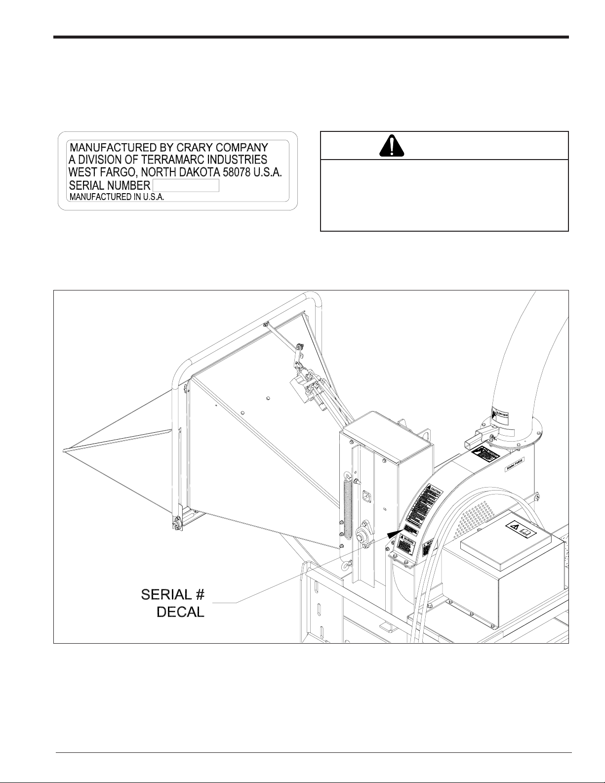
SERIAL NUMBER LOCATION
Always give your authorized Bear Cat dealer the serial number of your Crary Bear Cat Skid Steer Chipper when ordering
parts, requesting service or any other information. The serial number decal for Bear Cat Skid Steer Chipper is on the chipper
housing at the location called out below. Please record the serial number in the space provided below and on the warranty
and registration card.
WARNING
To prevent personal injury or property damage: Shut off
YXXXXX
Fig. # 1 Serial number decal
Serial Number ________________________
skid steer engine, remove ignition key, and make sure
that all moving parts have come to a complete stop,
before obtaining serial number, servicing, adjusting or
repairing.
Fig. # 2, Serial number decal location (Model # 74500 and 74800)
Skid Steer Chipper Operator’s Manual
I
Page 4

Section Description Page
SAFETY .................................................................................................................................... 1
OPERATION SAFETY ................................................................................................................. 2
FEED ROLLER SAFETY ............................................................................................................. 3
MAINTENANCE AND STORAGE SAFETY .................................................................................. 3
SAFETY DECAL LOCATIONS (74500 AND 74800) ...................................................................... 4
ASSEMBLY .................................................................................................................................... 5
MOUNTING THE CHUTE ............................................................................................................. 6
MOUNTING THE 4 POSITION VALVE.......................................................................................... 7
FEATURES AND CONTROLS IDENTIFICATION .......................................................................... 8
DESCRIPTION OF OPERATION .................................................................................................. 8
CHIPPING OPERATION .............................................................................................................. 8
FEATURES & CONTROLS ................................................................................................................................9
FEATURES AND CONTROLS IDENTIFICATION .......................................................................... 9
USE OF CONTROLS ................................................................................................................... 9
OPERATION .................................................................................................................................. 11
MOUNTING THE CHIPPER TO THE SKID STEER .................................................................... 11
INSTALLING THE FLUSH FACE COUPLERS ............................................................................ 12
HYDRAULIC SCHEMATIC ......................................................................................................... 13
OPERATING THE CHIPPER...................................................................................................... 14
CHIPPING GUIDE ...................................................................................................................... 15
FEED ROLLER SECURING INSTRUCTIONS ............................................................................. 16
Contents
SERVICE & MAINTENANCE ............................................................................................................................ 16
MAINTENANCE SCHEDULE ..................................................................................................... 17
SHARPENING CHIPPER BLADES ............................................................................................ 18
CHIPPER BLADE AND ANVIL CLEARANCE ............................................................................ 19
GREASING ............................................................................................................................... 20
CLEANING PLUGGED ROTOR ................................................................................................. 22
TROUBLESHOOTING ................................................................................................................ 23
BOLT TORQUE REQUIREMENTS ............................................................................................. 25
Skid Steer Chipper Operator’s ManualII
Page 5
Chipper Limited Warranty
Crary Bear Cat Chippers are warranted for one year from date of sale for consumers and commercial or
rental operations.
Within the above stated period, Crary Co. will replace any part(s) found to be defective in material and/or
workmanship, after the receipt of the part in our plant. Labor costs to replace these defective parts will be
paid at a Crary established labor rate and time allowed (flat rate) for repair. All transportation charges
incurred in shipping part(s) are the responsibility of the purchaser.
This warranty is void in the case of accidents, failure to perform normal maintenance, or failure to follow
those instructions listed in the service manual. This warranty is also in lieu of all other expressed warranties
and voids any implied warranty as to the merchantability or fitness of the product for a particular purpose
and of any other obligation on the part of Crary Co. Some states do not allow limitations on how long the
implied warranty lasts, so the above limitation may not apply to you.
This warranty applies only to parts or components which are defective, and does not cover necessary
repair due to normal wear, misuse, accidents, or lack of proper maintenance. This includes belts, pulleys,
and chipper blades. Regular routine maintenance of the unit to keep it in proper operating condition is the
responsibility of the owner.
All warranty repair work reimbursable by Crary Co. must be performed by an authorized Bear Cat service
dealer using Bear Cat approved replacement parts. Service dealers must hold onto damaged parts for
inspection at the request of Crary Co. Repair or attempted repair by anyone other than an authorized Bear
Cat service dealer is not reimbursable under the Crary Co. warranty. In addition, these unauthorized repair
attempts may result in additional malfunction, the correction of which is not covered by warranty.
Crary Co. is not liable for indirect, incidental, or consequential damages in connection with the use of this
product including any cost or expense or providing substitute equipment or service during periods of
malfunction or non-use.
Some states do not allow the exclusion of incidental or consequential damages, so the above exclusion
may not apply to you. This warranty gives you specific legal rights. You may also have other rights which
vary from state to state.
Be sure to note the chipper serial number in any correspondence with Crary Co. or any authorized Bear
Cat dealer.
Crary Company
A Division of TerraMarc Industries
237 12th St. NW • P.O. Box 849
West Fargo, ND 58078-0849
(701)282-5520 • FAX: (701)282-9522
www.bearcatproducts.com
www.terramarc.com
Skid Steer Chipper Operator’s Manual
III
Page 6

NOTICE
For testing purposes, fluids may have been added to this machine prior to
shipping. Specifically, this includes hydraulic fluid. Be careful with installing
and handling hydraulic lines, hydraulics may be under pressure. Refer to
page 10 of the owners manual for specific instructions.
Page 7
1
Safety
Section
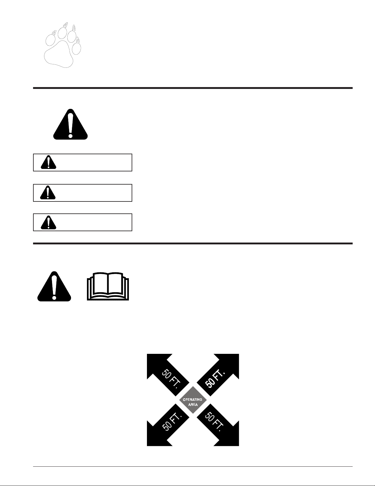
THE SAFETY ALERT SYMBOL
This is the safety alert symbol. It is used in this Owner / Operator’s Manual and on your machine
to alert you to potential hazards.
Whenever you see this symbol, read and obey the safety message that follows it. Failure to obey
the safety message could result in personal injury, death or property damage
DANGER
WARNING
CAUTION
BEFORE OPERATING
1. Read this Owner / Operator’s
manual carefully before operating
this equipment. Be completely
familiar with the controls and the
proper use of this equipment.
2. To prevent personal injury or death:
Stop chipper and loader engine.
Make sure that all moving parts
have come to a complete stop,
and disconnect quick couplers
from loader before servicing, adjusting or repairing.
Indicates an imminently hazardous situation that, if not avoided, will result in
death or serious injury.
Indicates a potentially hazardous situation that, if not avoided, could result in
death or serious injury.
Indicates a potentially hazardous situation that, if not avoided, may result in
minor or moderate injury.
equipment and on any of it’s attachments or accessories.
5. Do not allow children or any person unfamiliar with the use of the
unit to use this machine.
6. Keep the area of operation clear of
all persons, particularly small children. Keep bystanders at least
50 feet (15 meters) away from the
area of operation.
7. Do not operate this machine if you
are under the influence of alcohol,
medications, or substances that
can affect your vision, balance, and
judgement. Do not operate if tired
or ill. You must be in good health
to operate this machine safely.
8. Use only in daylight or good artificial light.
9. Never use without proper guards
in place.
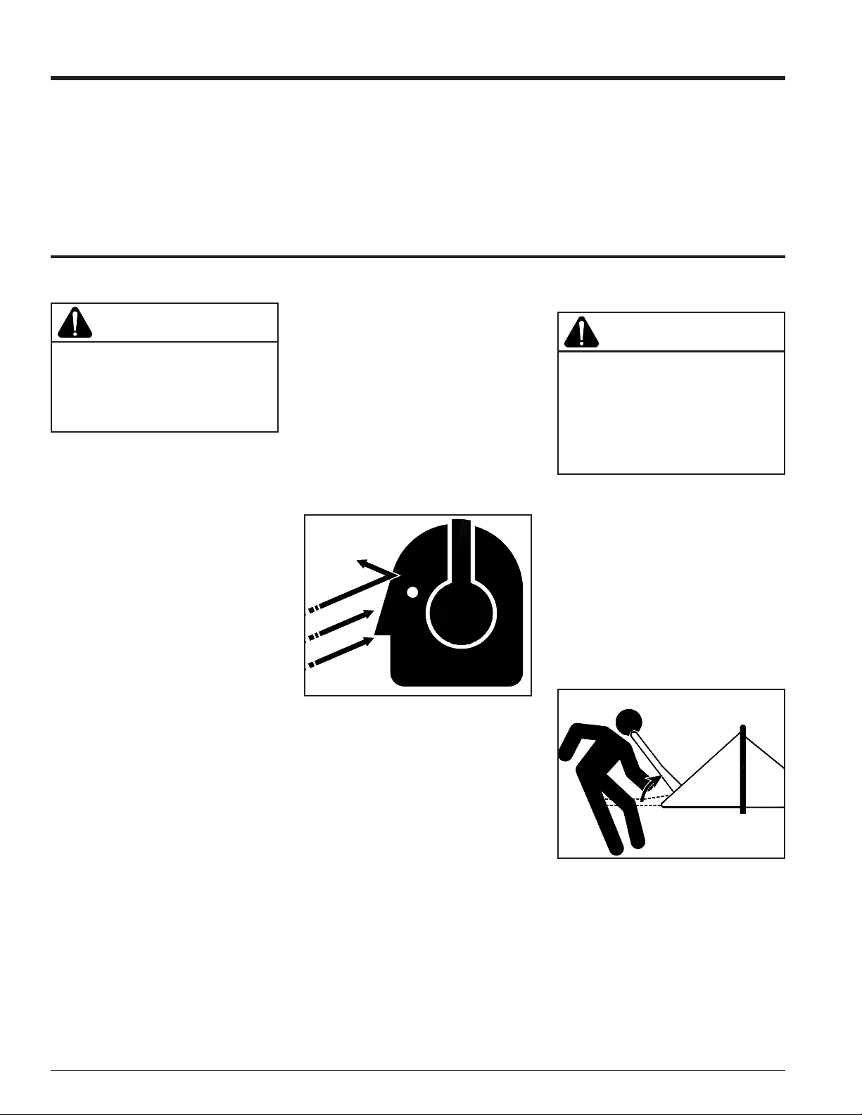
10. Wear safety glasses at all times
while operating this machine. One
pair of safety glasses is provided.
11. Wear hearing protection at all times
while operating this machine.
3. Keep safety decals clean and legible. Replace missing or illegible
safety decals.
4. Familiarize yourself with all of the
safety and operating decals on this
Page 1Skid Steer Chipper Operator’s Manual
Page 8
Safety
12. Avoid wearing loose fitting clothing. Never operate this machine
wearing clothing with drawstrings
that could wrap around or get
caught in the machine.
OPERATION SAFETY
DANGER
Keep hands, feet and clothing out of
inlets and discharge openings while
machine is operating to avoid serious personal injury or death.
1. Do not allow hands, or any part of
body or clothing, inside the feeding
chamber, discharge chute, or near
any moving parts.
2. Check the cutting chamber to verify
it is empty before starting the machine.
3. Exclude pieces of metal, rocks,
bottles, cans, and other foreign objects when feeding chipable material into the machine.
13. Check that all screws, nuts, bolts,
and other fasteners are properly secured before starting the machine.
Check all screws, nuts, bolts, and
other fasteners for proper tightness
to ensure everything is in proper
working condition. Check once in
the first two hours and every 10
hours thereafter.
5. Do not allow processed material to
build up in the discharge area; this
may prevent proper discharge and
can result in kickback of material
through the feed opening.
6. Stand clear of the discharge area
when operating this machine.
7. Keep your face and body back from
the feed opening.
14. Keep all guards, deflectors, and
shields in place and in good working condition.
15. Do not transport or move machine
while the machine is running.
WARNING
Material can kickup or shift suddenly
and cause serious injury or death.
• Wear eye, and hearing protection.
• Stand to the side of the feed chute.
• Release material and stand to
side of the feed table and chute.
9. When feeding material into feed
roller:
A. Wear eye, face and hearing
protection.
B. Release material and stand to
side of feed table and chute.
C. Keep metal objects, rocks,
bottles, cans and other foreign
objects out of chipper.
4. Shut off machine immediately if the
cutting mechanism strikes any foreign object or the machine starts
making an unusual noise or vibrating. Allow the machine to stop completely. After machine stops:
A. Shut off skid steer engine.
B. Remove ignition key.
C. Inspect for damage.
D. Replace or repair any
damaged parts.
E. Check for and tighten any
loose parts.
Page 2 Skid Steer Chipper Operator’s Manual
8. Do not climb onto chipper feed
chutes or frame when operating. Do
not overreach. Keep proper balance
and footing at all times.
WRONG
Page 9
Safety
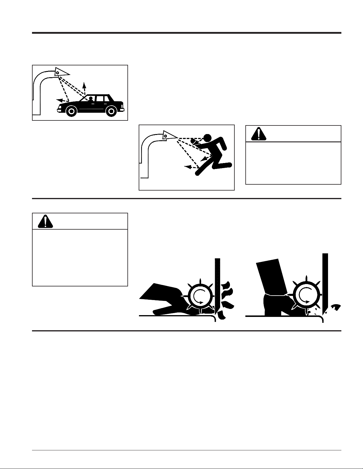
10. Setting up your chipping site so
you are not endangering the
public is critical for safety.
WRONG
11. Check the bolts correct torque
every 10 hours of operation (See
torque chart at back of manual).
12. Rotate the discharge tube to face
the opposite direction of the towing vehicle before towing. This
FEED ROLLER SAFETY
WARNING
prevents the discharge tube from
projecting over the trailer wheels
and striking foreign objects.
13. Flying debris can cause serious
injury or death and property damage.
14. Keep bystanders away from discharge chute.
WRONG
2. Never climb onto chipper feed
chute or table when operating.
15. Position discharge chute away
from bystanders and other property when opening.
16. Keep metal objects, rocks,
bottles, cans, and other foreign
objects out of chipper.
17. Check the bolts torque on the
chipper every 10 hours of operation.
WARNING
Failure to maintain proper fastening torque on chipper blade bolts
may result in severe damage to the
chipper and / or personal injury.
4. No riders allowed, keep off the at-
tachment.
To prevent personal injury or death:
Stop chipper and loader engine.
Make sure that all moving parts
have come to a complete stop, and
disconnect quick couplers from
loader before servicing, adjusting,
or repairing.
1. Feed roller and rotating chipper
can cause serious injury or death.
Keep hands, feet and clothing
away from feed roller chipper
blades.
3. Do not over reach. Keep proper
balance and footing.
WRONG
MAINTENANCE AND STORAGE SAFETY
1. Shut off the skid steer, disconnect
the hydraulics, remove the ignition
key when this equipment is stopped
for service, inspection, storage.
2. Unhook the unit from the machine
and store detached.
3. Do not place the machine in an area
where children can play on or
around.
4. Replace any missing or unreadable
safety decals. Refer to the parts
manual for part numbers when ordering safety decals from an area
Bear Cat dealer.
5. See skid steer owners manual or
contact the manufacturer for safety
instructions and decals.
WRONG
Page 3Skid Steer Chipper Operator’s Manual
Page 10
Safety
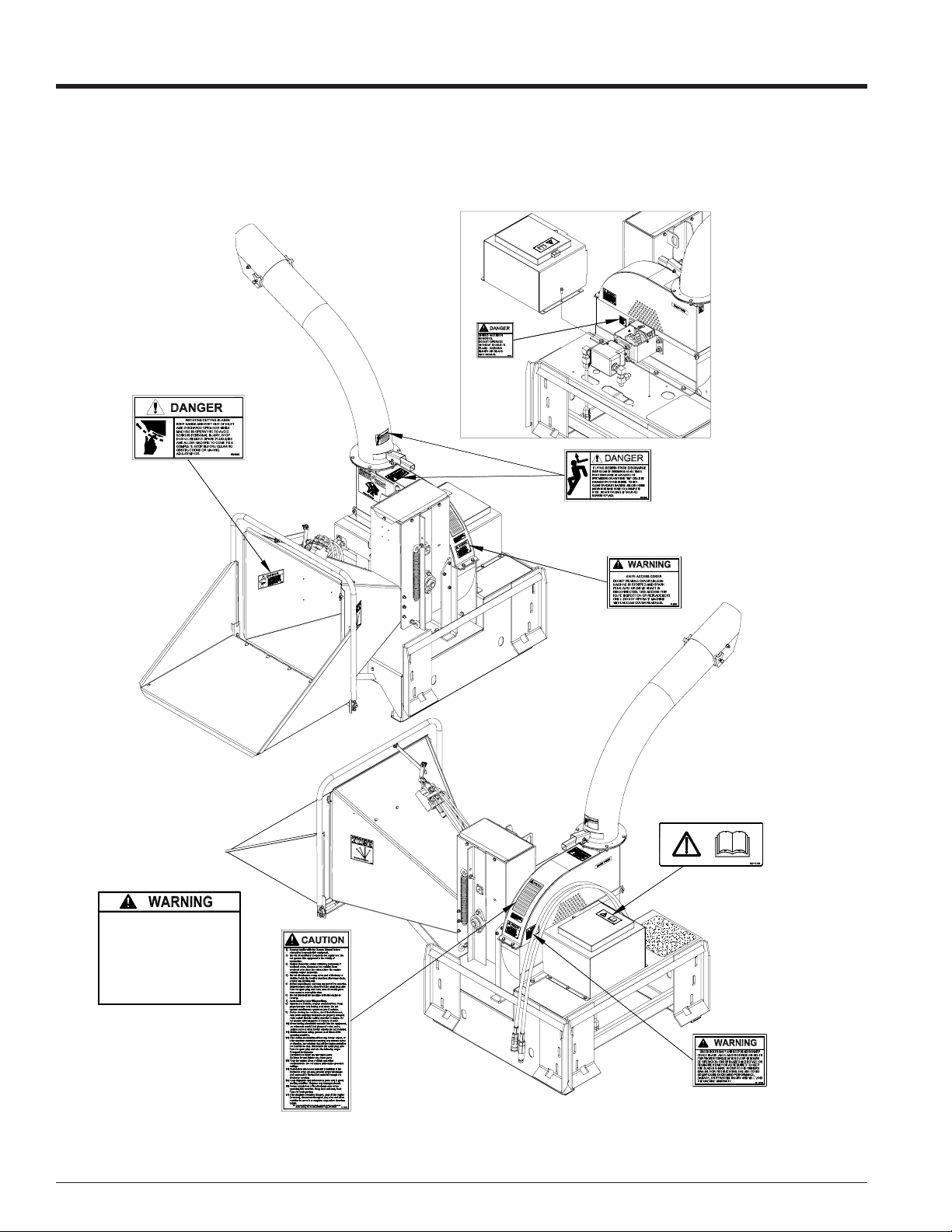
SAFETY DECAL LOCATIONS (74500 AND 74800)
Familiarize yourself with all of the safety and operational decals on the machine and the associated hazards. Make certain
that all safety decals and operational decals on this equipment are kept clean and in good condition. The decals are shown
below at reduced sizes. If you need a replacement decal, please refer to the parts catalog. Decals that need replacement
must be applied to their original locations.
P/N 17423
P/N 17837
P/N 16558
Guards and shields are
removed for illustrative
purposes only; do not
operate without guards
and shields in place and
functioning properly.
P/N 16085
P/N 13711-00
P/N 17846
Fig. #3, 74500 and 74800 decal locations
Page 4 Skid Steer Chipper Operator’s Manual
P/N 12010
Page 11

Assembly
2
Section
Your chipper may arrive totally or partially assembled. If your machine arrives partially assembled, you may need to perform
the steps in this section.
ASSEMBLY INSTRUCTIONS (74500 AND 74800)
Installing the Discharge Tube
WARNING
To prevent personal injury or property damage: Shut off skid steer
engine, disconnect hydraulics, remove ignition key and make sure
that all moving parts have come to
a complete stop, before servicing,
adjusting or repairing.
The Bear Cat Skid Steer Chipper is
shipped an a disassembled state. The
unit will need to be assembled before
use.
1. Remove Bear Cat Skid Steer Chipper from the shipping pallet.
2. Lightly grease the chipper outlet
flange.
3. Position the discharge tube over the
chipper outlet flange and slide on
using the tube latch (See Fig. #4).
4. Install the retaining rings with the
hardware provided in the owners kit.
5. Tighten the bolts so the discharge
tube does not rock on the flange.
Do not over tighten the bolts, as the
flange will distort.
6. Lift the latch on the handle of the
discharge tube and position the tube
in the desired position.
7. Release the latch making sure it
locks in one of the holes on the chipper flange.
8. Add one shot of grease to the greaze
zerk on the discharge flange. Rotate the discharge tube to spread
grease.
SLIDE DISCHARGE
TUBE ONTO CHIPPER
CHIPPER OUTLET
FLANGE
Fig. #4, Attaching discharge tube
CHIPPER
DISCHARGE
SPACER
CHIPPER
DISCHARGE
3/8" NYLOCK
NUT
CLAM
3/8" X 1-1/4"
BOLT
Fig. #5, Securing discharge tube
Page 5Skid Steer Chipper Operator’s Manual
Page 12

Assembly
MOUNTING THE CHUTE
The chipper chute must be mounted to the roller support
weldment. On the 74800 the chute is held in place with 8
bolts, on the 74500the chute is held in place with 6 bolts.
Both models use a chute support.
Fig. #6, Mounting the chute to the roller support. NOTE: The 74800 is
mounted with 8 bolts. The 74500 is mounted with 6.
Mounting the chute to the roller support:
1. Place the chute on the roller support weldment. Have
someone assist if necessary.
2. Align the chute with the mounting holes.
3. Insert all 6 or 8 (depending on model) 3/8” carriage bolts
into the mounting holes. It may be helpful to align the
holes with a punch.
4. Place washers and nuts on the opposite side of the bolts
and tighten to proper torque.
Fig. #7, Mounting the chipper chute support.
Mounting the chute support:
1. Make sure the chute is mounted to the roller support
weldment.
2. Place the chute support underneath the chute.
3. The side of the chute support with the two mounting holes
is orientated towards the chipper base.
4. Attach the chipper chute to the base with the provided 3/
8” bolts, washers and nuts. It may help to slightly lift the
chipper chute.
5. Align the other hole of the chipper chute support with the
hole in the chipper chute.
6. Insert the other 3/8” bolt , washer, and nut. Tighten to
proper torque.
Page 6 Skid Steer Chipper Operator’s Manual
Page 13

MOUNTING THE 4 POSITION VALVE
Assembly
Attaching the 4 position valve:
1. Place the 4 position valve on the chipper chute over the
(3) pre-drilled mounting holes.
2. From the inside of the chipper chute, using the 5/16” x 3/
4” bolts (P/N 15003), and washers (P/N 15250) thread
the bolts into the 4 position valve
3. Tighten 5/16” hardware to proper torque.
4. Attach the valve control lever according to the diagram
below.
5. Tighten the 5/16” bolt to the proper torque.
Fig. #8, Mounting the four position valve.
(as needed)
Fig. #9, Connecting the valve control lever to the 4 position valve.
Page 7Skid Steer Chipper Operator’s Manual
Page 14

COU
3
Features & Controls
Section
FEATURES AND CONTROLS IDENTIFICATION
Learn the location of the features and controls on your machine before operating.
MODEL # 74500 and 74800
CONTROL ARM
CHIPPER CHUTE
EXTENSION
TRAY
DISCHARGE
LOCK
KNIVE ACCESS
COVER BOLT
DISCHARGE
DEFLECTOR
DISCHARGE
TUBE
CHIPPER BLADE
ACCESS COVER
OWNERS MANUAL
COMPARTMENT
UNIVERSAL SKID-STEER
MOUNT
NOTE
All references to left,
right, front and rear of
the machine are determined by the illustrations shown.
UNIVERSAL SKID-STEER
MOUNT
FEMALE HYDRAULIC
COUPLER
MALE HYDRAULIC
PLER
Fig. #10, 74500 and 74800 features and controls
DESCRIPTION OF OPERATION
Understanding how your machine works will help you achieve the best results when using your chipper. The following
description defines the operation of your machine.
CHIPPING OPERATION
The chipping operation takes place at the front side of the machine, where hardened steel chipper blades are mounted on
a rotating rotor assembly. Material fed into the chipper chute is sliced into small chips and propelled out through the
discharge chute. The chips can be diverted into a truck or onto the ground.
Page 8 Skid Steer Chipper Operator’s Manual
Page 15

FEATURES AND CONTROLS IDENTIFICATION
Learn the location of the features and controls on your machine before operating.
MODEL # 74500 and 74800
ROTOR
ASSEMBLY
CHIPPER
BOTTOM
FEED ROLLER
FEED RATE
CONTROL
Features & Controls
FEED ROLLER
HOUSING & FEED
ROLLER
WARNING
To prevent personal injury or property damage: Shut off skid steer
engine, remove ignition key and
make sure that all moving parts have
come to a complete stop, before
servicing, adjusting or repairing.
USE OF CONTROLS
Model # 74500 and 74800.
Control Arm: The control arm has four
postions and is used to engage the feed
roller. The four positions are: reverse,
stop, forward, reverse.
Feed roller rate control: The feed
roller speed is adjustable with a hand
crank located below the chipper feed
table. Use a slower feed roller speed
when feeding large branches into the
chipper. Increase the feed roller speed
when feeding small branches into the
Fig. #11, 74500 and 74800 features and controls
chipper. Turning the crank counterclockwise decreases the feed roller
speed. Turning the crank clockwise increases the feed roller speed.
Discharge deflector: the discharge
deflector can be used to aim the spray
of wood chips from the chipper.
Discharge lock: The discharge lock
serves to lock the rotating discharge
tube. The lock is disengaged by pressing down on the discharge handle. The
discharge tube is then free to pivot. To
engage the lock release the handle and
center the locking pin on a hole in the
chipper outlet flange.
Chipper chute extension tray: The
chipper chute extension tray is lowered
by releasing the chipper chute extension latches.The extension tray then
pivots down.
Page 9Skid Steer Chipper Operator’s Manual
Page 16

4
Operation
Section
WARNING
Before operating your machine, be
sure you read and understand all
safety, controls and operating instructions in this Owner/Operators
manual and on your machine.
Failure to follow these instructions
can result in serious injury or property damage.
As with any other piece of outdoor
power equipment, getting the “feel” for
how your machine operates and getting
to know the best techniques for
particular jobs are important to overall
good performance.
Read this section thoroughly before you
use the machine. The instructions
given here will help you become familiar
with your machine and have you
operating efficiently in a short time.
This Section explains:
• Mounting the Chipper to the Skid Steer
• Installing the Flush Face Couplers
• Operating the chipper
• Chipping Guide
• Feed Roller Securing Instructions
• Loading the Chipper
NOTE
The 74800 requires a minimum hydraulic flow of 25 gallons per minute.
Fig. #12, Connected chipper
Page 10 Skid Steer Chipper Operator’s Manual
Page 17

MOUNTING THE CHIPPER TO THE SKID STEER
The chipper can be mounted to the skid
steer in two locations. The recommended location is with the feed table
sitting at the front of the loader. However, if space is a concern, the unit can
be mounted with the feed table sitting
to the right of the machine.
1. Tilt the universal skid steer mount
forward.
2. Make sure that the wedges are fully
raised.
3. Drive the skid steer forward until the
top edge of the coupler is completely
under the top flange on the chipper.
4. Tilt the unit backward until the chipper is slightly off the ground.
Operation
5. Kill the engine and exit the machine
to push down the wedges using the
universal skid steer mount levers
(See Fig. #10). On automated models stay in the machine and engage
the wedges.
WARNING
The wedges must extend through
the holes in the mounting frame of
the chipper to securely fasten the
chipper to the universal skid steer
mount. Failure to secure wedges
can allow attachment to come off
and cause injury or death.
Fig. #13, Connecting the skid steer
Fig. #14, Securing the wedges
Page 11Skid Steer Chipper Operator’s Manual
Page 18

Operation
INSTALLING THE FLUSH FACE COUPLERS
WARNING
Hydraulic lines may be under pressure due to testing done at the factory.
The Bear Cat Skid Steer Chipper is
equipped to attach to flush face couplers (See Fig. #11). The chipper is
shipped with 12 sized hydraulic couplers fitted on the hoses. A tie wrap is
used to indicate the pressure line. Be
sure to connect the hydraulic hoses
to the proper ports.
If the skid steer is fitted with anything
other than 12 sized flush face couplers,
on the main lines, it will be necessary
to replace the couplers supplied with
the chipper.
The chippers are also equipped with a
case drain hose. The case drain is used
to eliminate pressure on the chipper’s
hydraulic motor. The motor is rated for
250 to 300 psi of back pressure.
Most high flow skid steer loaders are
equipped with case drain line. Standard flow skid steer loaders typically
are not. If the back pressure tandard
flow skid steer is over 300 psi, a
case drain line will have to be
added. Contact your skid steer
dealer for details. Not adding a
case drain line voids chipper warranty.
If the back pressure is below 300 psi
the case drain line can be left idle or
removed.
To connect:
1. Before connecting make sure to relieve the hydraulic pressure in the skid
steer, using the skid steer system to
relieve pressure.
2. Remove dirt and debris from the surface of the couplers.
3. Visually check for the couplers for
damage, replace if damage is found.
4. Install the male coupler into the female coupler. Full connection is made
when the ball release sleeve slides forward on the female coupler.
5. Turn the sleeve so that it is rotated
away from the locking pin to prevent
accidental disconnection.
Fig. #15, Installed couplers
To disconnect:
1. Relieve hydraulic pressure.
2. Rotate ball sleeve so that the grooves
are aligned with the pins in the female
coupler.
3. Retract the sleeve on the female
coupler until the couplers disconnect.
4. Repeat the procedure for all hoses.
6. Repeat procedure for all hoses, including the smaller case drain hose.
Page 12 Skid Steer Chipper Operator’s Manual
Page 19

HYDRAULIC SCHEMATIC
Operation
Fig. #16, Hydraulic Schematic
Page 13Skid Steer Chipper Operator’s Manual
Page 20

Operation
OPERATING THE CHIPPER
WARNING
Do not attempt to bypass the safety systems of the
skid steer loader.
Pre-operation
1. Wear appropriate eye, face, and hearing protection. Wear
gloves that fit tight against the wrist.
2. Remove the rubber latches from both sides of the feed
table.
3. Lower the chipper feed table.
feed roller is in the neutral position) to supply power to
the unit. The chipper will start to spin.
3. Place the feed roller in the opeating position and bring the
unit up to speed.
4. The chipper is ready to chip.
Stopping the chipper
1. One operator should disengage the feed roller after all
material has been cleared from the chipper.
2. The second should then slow down the engine of the skid
steer to idle and after several seconds, disengage the
skid steer hydraulics.
Chipper operation
1. The feed roller control has four positions:
A - Reverse: Reverses the direction of the feed roller. Use
this function to unplug the feed roller.
B - Stop: Stops the feed roller.
C - Forward: Feeds brush into the chipper.
D - Reverse: Reverses the direction of the feed roller.
Fig. #17, Anti-luse coupler
4. Check that the feed roller is clear of material.
5. Place the feed roller control in the “stop” position.
6. Push down the latch and rotate the discharge chute to
the desired position.
7. Release the handle and move the chute until it locks the
chute in position.
Starting the chipper
Running the Bear Cat Skid Steer Chipper is a one or two
man operation. If the system mandates an operator in the
driveseat, two people are needed. The chipper engages with
the hydraulics of the skid steer, as do most skid steer powered attachements.
2. The feed roller speed is adjustable with a hand crank
located below the chipper feed table. Use a slower feed
roller speed when feeding large branches into the chipper. Increase the feed roller speed when feeding large
branches into the chipper. Turning the crank counterclockwise decreases the feed roller speed. Turning the crank
clockwise increases the feed roller speed.
Fig. #18, Feed roller speed adjustment
1. Set parking brake.
2. Engage the hydraulics of the skid steer (providing the
Page 14 Skid Steer Chipper Operator’s Manual
Page 21

CHIPPING GUIDE
Operation
The Bear Cat chipper is designed to chip a variety of materials into a more readily decomposing or handled condition.
The following guidelines can be used to help you get started.
WARNING
Do not leave machine unattended, or attempt any inspection or service unless the skid steer engine is
stopped, the hydraulic system disconnected, and the
key removed from the key switch.
NOTE
Please read and follow all safety instructions in
this manual. Failure to operate the chipper in accordance with the safety instructions MAY RESULT
IN PERSONAL INJURY!
• Run unit at full operating speed before starting to chip
material.
• Feed brush from the side of the chipper chute, rather
than from the front. Then, step aside to avoid being hit by
the brush moving into the chipper.
• Do not lean over the chipper chute to push objects into
the cutting device.
• Never push brush into the chipper chute with your feet.
• Place limb, butt end first, into the chipper chute until it
contacts the feed roller.
• Stop the material feeding and allow the engine to recover
if the engine slows to where it may stall.
• Chipping dead, dry material will create heat and dull the
chipping blades quickly.
• Alternate greener material with dry material to lubricate
the chipping blades for longer life and better performance.
• The chipping blades will become dull and will require periodic sharpening. Refer to Service and Maintenance section.
• The 74500 is most effective when chipping 3” in diameter
material. Five-inch material will fit into the machine, though
it may bog the chipper down. The 74800 is most effective when chipping 5” diameter material. Eight-inch material will fit in the machine, though it may bog the chipper
down.
• As soon as the feed roller has started to pull the brush
into the chipper, let go of the brush and step away from
the feed table.
• Never use shovels or forks to push brush. They can be
chipped, are expensive to replace, and cause extensive
damage. In addition, metal pieces can come back to injure or kill.
IMPORTANT
Exclude pieces of metal, rocks, bottles, cans, and
other foreign objects when feeding chipable material into the machine.
• If brush gets caught in the feed roller, causing a jam,
move the feed roller control to the reverse position. If the
roller is still jammed shut off the skid steer, disconnect
the hydraulic lines, and clean the rotor.
Page 15Skid Steer Chipper Operator’s Manual
Page 22

Operation
FEED ROLLER SECURING INSTRUCTIONS
WARNING
Feed Roller support must be secured in the up position
prior to servicing chipper feed area. Feed Roller can fall
and cause bodily harm.
Before the chipper feed area is serviced, the feed roller support
must be locked in the upright position. To secure the feed
roller support, proceed as follows.
1. Turn the 1/2" wingnut located on the bottom of the bottle
jack to the right, engaging the jack.
2. Using the jack handle, pump the jack to the most upright position. This raises the feed roller support.
3. Place a 1/2” x 1 1/2” bolt, or similar device, through the
hole called out on Fig. #2. This will ensure the feed
roller support cannot fall from the upright position.
4. Service or clear the unit of debris. Do not place hands
underneath the feed roller if possible.
5. To lower the feed roller support, remove the bolt and
then release tension on the jack by turning the 1/2"
wingnut to the left.
6. Before operation turn and tighten the 1/2" wingnut fully
to the right.
Fig. #19, Bolt insertion hole
Page 16 Skid Steer Chipper Operator’s Manual
Page 23

5
Service & Maintenance
Section
WARNING
To prevent personal injury or property damage: Shut
off skid steer engine, disconnect hydraulics, remove
ignition key, and make sure that all moving parts have
come to a complete stop before, servicing, adjusting or
repairing.
SERVICE AND MAINTENANCE SCHEDULE
MAINTENANCE SCHEDULE
The following items listed in the service and maintenance
schedule are to be checked, and if necessary, corrective
action should be taken. The most important maintenance
is to keep the chipper blades sharp. This schedule is designed for units operating under normal conditions. If the
unit is operating in adverse or severe usage conditions it
may be necessary for the items to checked and serviced
more frequently.
FREQUENCY
COMPONENT
NUTS AND BOLTS CHECK
CHIPPER BLADES CHECK, SHARPEN IF NEEDED
ENTIRE MACHINE CLEAN
ENTIRE MACHINE LUBE ALL GREASE POINTS
MAINTENANCE
REQUIRED
BEFORE EACH USE EVERY 50 HOURS
•
•
•
•
Page 17Skid Steer Chipper Operator’s Manual
Page 24

Service & Maintenance
SHARPENING CHIPPER BLADES
The chipper blades will eventually become dull, making chipping difficult and adding extra strain on the machine. It is
recommended that the chipper blades be sharpened
every 5-15 hours of chipper operation. To remove the
chipping blades for sharpening, follow the procedure below
WARNING
To prevent personal injury or property damage: Shut off
skid steer, disconnect hydraulics, remove ignition key,
and make sure that all moving parts have come to a complete stop, before servicing, adjusting or repairing.
The chipping blades are sharp! Use care when working
on machine to avoid injury.
Removing the chipper blades:
1. Disconnect the hydraulic hoses from the skid steer.
2. Position the chipper chute to the side of the chipper.
3. Remove the two bolts on the chipper housing.
4. Tip the chute and housing away from the chipper to ex-
pose the rotor and the blades.
5. Use a pry bar between two of the fan blades to prevent
the chipper from rotating during chipper blade removal
and installation.
6. Remove the blades (Qty. 4) making sure not to slip the
wrench, the chipper blades are sharp.
7. The chipper blades are reversible. If the blades have not
been reversed flip the blades 180 degrees and reinsert.
8. If the chipper blades need to be sharpened refer to the
sharpening blades section of the manual.
9. Inspect all components of the chipper for damage and
replace if necessary.
Sharpening the Blades:
1. When sharpening the blades grind the angled edge of the
chipping blade to 45 degrees. This is best accomplished
on a slow-speed wet grinder. If a bench grinder is used
be careful when grinding so that the blade material does
not get too hot and change color–this will remove the
blade's special heat treated properties.
2. Be sure to use short grinding times and cool with water
between grinding.
3. Try to remove an equal amount off each blade to maintain
balance.
NOTE
Never sharpen or grind on the back side of the chipper
blade. This will cause the edge to roll and the chipping
blade will be damaged, causing poor chipping and feeding of material. Small imperfections, nicks, burrs, etc. on
the flat side of the blade will not affect performance of the
machine.
Installing the blades:
1. Remove any accumulated material in the bottom of the
chipper drum.
2. Reinstall the chipper blades (Qty. 4) and tighten the bolts
to a torque of 20 ft. lbs. (74500) or 75 ft. lbs. (74800).
3. Check anvil clearance and adjust if necessary.
4. Close the chipper housing and reattach with removed
bolts to a torque of 25-28 ft.-lbs.
5. Reconnect machine hydraulics.
IMPORTANT
Do not exceed the recommended torque values of 20
ft. lbs. (74500) or 75 ft. lbs. (74800) when tightening
the bolts for the chipper blades.
MOUNTING
SHARPENED
SURFACE
SURFACE
DO NOT GRIND
45°
MOUNTING
SURFACE
DO NOT GRIND
Fig. #20, Sharpening Chipper Blades
Page 18 Skid Steer Chipper Operator’s Manual
CHIPPER
BLADE
SHARPENED
SURFACE
Tips:
Poor chipping performance is usually a result of dull chipping blades. If your chipper's performance has decreased,
check for the following symptoms. If the machine shows
these symptoms, sharpen the blades.
1. Severe vibration when feeding material into the chipper.
2. Chips discharge unevenly or have stringy tails–especially
when chipping green branches.
Before you sharpen the chipping blades, check for permanent damage. Replace the blade if:
1. The blade is cracked (especially around the bolt holes)
or the edges are too deeply chipped to be ground smooth.
2. The base of the cutting edge is worn or has been resharpened so that it is too close to the rotor chipping
slot.
Page 25

CHIPPER BLADE AND ANVIL CLEARANCE
Setting chipper blade clearance
1. The blade to anvil clearance is 1/16”
to 1/8”. The chipper must be between
these specifications at all times.
2. Adjust the anvil by loosening the two
(74500) or three (74800) anvil bolts.
3. On the 74500 move the anvil assembly in or out by turning the nuts on the
block adjuster weldment.
4. On the 74800, with the three anvil
bolts loosened, adjust the anvil to the
desired position.
4. If the anvil cannot be moved to specifications due to wear, rotate the anvil
or replace the anvil.
Service & Maintenance
5. Secure all hardware and adjust to
torque.
Fig. #21, Anvil and chipper blade clearance
Page 19Skid Steer Chipper Operator’s Manual
Page 26

Service & Maintenance
GREASING
Use an SAE multi-purpose high temperature grease with
extreme pressure (EP) performance meeting or exceeding
the NLGI # 2 rating for all requirements. Also acceptable is
an SAE multi-purpose lithium based grease.
WARNING
To prevent personal injury or property damage: Shut off
skid steer engine, disconnect hydraulics, remove ignition key, and make sure that all moving parts have come
to a complete stop before servicing, adjusting, or repairing.
Care should be taken when re-greasing bearings to not overfill
the bearing. Over greasing can lead to overheating and/or
unsealing the bearing seals.
1. Use a hand-held grease gun for all greasing.
2. Wipe grease fitting with a clean cloth before greasing,
to avoid injecting dirt and grit.
3. Replace and repair broken fittings immediately.
4. If fittings will not take grease, remove and clean thoroughly. Also clean lubricant passageway. Replace fitting if necessary.
5. Grease and oil the unit as illustrated.
Fig. #23, Grease every 50 hours
Fig. #24, Grease every 50 hours
Fig. #22, Oil yearly
Page 20 Skid Steer Chipper Operator’s Manual
Page 27

h50
Service & Maintenance
Fig. #25, Grease every 50 hours
Fig. #27, Grease every 50 hours
Fig. #26, Grease every 50 hours
Fig. #28, Same zerk as Fig. #26, shown with shield removed.
WARNING
The shield was removed for illustrative purposes only; DO
NOT run the machine without guards or shields in place
and functioning.
Page 21Skid Steer Chipper Operator’s Manual
Page 28

Service & Maintenance
CLEANING PLUGGED ROTOR
WARNING
If the machine becomes plugged, shut off the skid steer
engine, disconnect the hydraulics, remove ignition key,
and allow the machine to come to a complete stop before
clearing debris. Do not operate machine without proper
guards and screens in place.
Cleaning the Rotor:
1. Stop skid steer engine, disengage hydraulics, and allow
machine to come to a complete stop.
2. Position the chipper chute to the side of the chipper.
3. Remove the two bolts on the chipper housing.
4. Tip the chute and housing away from the chipper to ex-
pose the rotor and the blades.
5. Clean the debris out of the chipper. Turn the rotor by hand
to be sure it is free to rotate. Check for damage to the
rotor.
Cleaning the Feed Roller:
A bottle jack is mounted on the chipper to raise the feed
roller. This allows plugged debris to be easily removed from
the roller if the reverse function fails to dislodge the debris.
To operate the jack:
1. Turn the 1/2” wingnut located on the bottom of the jack to
the right, engaging the jack.
2. Using the jack handle pump the jack, connected to the
feed roller, to the desired location.
3. Clear the unit of debris. Do not place hands underneath
the feed roller.
4. Once the debris has been cleared release tension on the
jack by turning the 1/2” wingnut to the left and lowering
the feed roller.
5. Before operation turn and tighten the 1/2” wingnut fully to
the right.
6. Close the top housing.
7. Reattach the two bolts securing the chipper housing.
8. The machine is ready for operation.
Page 22 Skid Steer Chipper Operator’s Manual
Page 29

Service & Maintenance
TROUBLESHOOTING
Before performing any of the correction in this troubleshooting chart, refer to the appropriate information contained in this
manual for the correct safety precautions and operating or maintenance procedures. Contact your nearest dealer or the
factory for service problems with the machine.
Problem Possible Cause Correction
Feed roller does not engage.
Chipper is hard to feed.
Chipper vibrates excessively.
Chipper does not turn. No hydraulic flow.
Chipper does not discharge
chips.
Low hydraulic flow due to low engine
RPM.
1 - Plugged discharge chute. 1 - Clear discharge chute.
2 - Dull chipper blades. 2 - Sharpen blades.
3 - Damaged chipper blades. 3 - Replace damaged blades.
4 - Improper blade clearance. 4 - Adjust clearance.
1 - Chipper not correctly attached to
skid steer.
2 - Damaged chipper blades. 2 - Replace damaged blades.
Not enough hydraulic flow.
1 - Wedges are not fully extened. 1 - Retract wedges.
Move loader engine speed to
higher RPM.
1 - Check for correct mounting of
the chipper to the skid steer
Check quick couplers connection.
Check for damaged hose ends
and fittings.
Make sure enough flow is
provided by the skid steer.
Chipper does not seat
properly on the skid steer.
2 - Mud, dirt or stones are lodged
between the chipper and the skid
steer.
2 - Remove debris from between
the chipper and the skid steer.
Page 23Skid Steer Chipper Operator’s Manual
Page 30

Specifications
5” and 8” Skid Steer Chipper (Model 74500 and 74800)
"H"
"I"
"A"
"C"
"G"
"E"
"F"
"B"
"D"
MODEL 74500 & 74800 DIMENSIONAL DATA
MODEL "A" "B" "C" "D" "E" "F" "G" "H" "I"
74500
74800
ROTOR SPEED 1500 RPM 1500 RPM
FRAME MATERIAL 1/4" THICK STEEL CONSTRUCTION 1/4" THICK STEEL CONSTRUCTION
CHUTE SIZE 32" X 36" 32" X 36"
DRIVE SYSTEM HYDRAULICS HYDRAULICS
SKID-STEER HYDRAULICS STANDARD OR HIGH-FLOW HIGH-FLOW
CHIPPER BLADES (QTY. 4) CHIPPER BLADES (TOOL STEEL) (QTY. 4) CHIPPER BLADES (TOOL STEEL)
ROTOR SIZE 20” X 1-1/4", 140 POUNDS 30” X 1-1/4”, 275 POUNDS
WEIGHT 1145 LBS. 1525 LBS.
CHIPPER OPENING SIZE * 5-1/2" X 7" 9" X 9"
CONTINUOUS CHIPPING SIZE * 3” (76.2MM) DIAMETER 5” (127MM) DIAMETER
DISCHARGE TUBE ROTATING ANGLE
RANGE
* Continous Chipping Size rating refers to the suggested feeding size of limbs for normal operat ions. Limbs up to the Chipper O pening Size may be
fed, but decreased per formance will occur.
91.9 102.2 56.4 46.0 48.1 49.2 23.3 29.6 6.0
92.2 103.3 59.6 46.0 45.4 56.5 23.6 37.8 8.0
SPECIFICATIONS
MODEL 74500 74800
360° 360°
Page 24 Skid Steer Chipper Operator’s Manual
Page 31

Specifications
BOLT TORQUE REQUIREMENTS
The tables shown below give correct torque values for various bolts and capscrews. Tighten all bolts to the torques specified
in chart unless otherwise noted. Check tightness of bolts periodically, using this bolt torque chart as a guide. Fasteners
should be replaced with the same grade bolt. Tighten serrated or center-lock nuts to the full torque value.
Do not use these values if a different torque value or tightening procedure is given for a specific application. Torque values
listed are for general use only.
SAE
Grade
and
Head
Markings
SAE - 8SAE - 2ASAE - 5
BOLT DIAMETER
UNIFIED INCH BOLT TORQUE VALUES
(unless otherwise specified in the manual)
Bolt
Diameter
"A"
1/4" 7.5 5.5 12 9 17 12.5
5/16”1511251835 26
3/8” 27 20 44 33 63 46
7/16”44327052100 75
1/2” 67 50 110 80 150 115
9/16” 95 70 155 115 225 160
5/8” 135 100 215 160 300 225
3/4” 240 175 375 280 550 400
7/8” 240 175 625 450 875 650
1” 360 270 925 675 1300 975
1-1/8” 510 375 1150 850 1850 1350
1-1/4” 725 530 1650 1200 2600 1950
1-3/8” 950 700 2150 1550 3400 2550
1-1/2” 1250 930 2850 2100 4550 3350
SAE 2
(N.m) (ft - lb) (N.m) (ft - lb) (N.m) (ft - lb)
Bolt Torque *
SAE 5 SAE 8
Torque figures indicated at left are
valid for non-greased or non-oiled
threads and heads unless otherwise specified. Therefore, do not
grease or oil bolts or capscrews
unless otherwise specified in this
manual. When using locking elements, increase torque values by
5%.
* Torque value for bolts and
capscrews are identified by their
head markings.
SPECIAL TORQUE REQUIREMENTS
LOCATION ON MACHINE HARDWARE DESCRIPTION
74500 CHIPPER BLADE MOUNTING BOLTS 5/16" X 1 1/4" HEX HD. GRADE 8 BOLTS (QTY 8) 20 ft-lbs 27 N.m
74800 CHIPPER BLADE MOUNTING BOLTS 1/2" X 2 1/2" FLAT HYD SKT. (QTY 12) 75 ft-lbs 101 N.m
TORQUE
(UNIFIED INCH))
TORQUE
(METRIC)
Page 25Skid Steer Chipper Operator’s Manual
Page 32

Crary Company
A Division of TerraMarc Industries
237 12th St. NW • P.O. Box 849
West Fargo, ND 58078-0849
(701)282-5520 • FAX: (701)282-9522
www.bearcatproducts.com
www.terramarc.com
Manufactured in the
United States of America
by Crary Company
 Loading...