

Page 1

5 AND 8 INCH
MADE WITH PRIDE IN THE...
SKID STEER CHIPPER
74500 - 5" SKID STEER
74800- 8" SKID STEER
OW N E R ' S M A N UAL
PN: 13940-00 R040407
Companion to 13939-00
Page 2

Before You Begin
MANUFACTURED BY CRARY INDUSTRIES
MANUFACTURED IN U.S.A.
XXXXXX
WEST FARGO, NORTH DAKOTA 58078 U.S.A.
SERIAL NUMBER
DEAR ECHO BEAR CAT CUSTOMER
Thank you for purchasing a ECHO Bear Cat product. The ECHO Bear Cat line is designed, tested, and manufactured
to give years of dependable performance. To keep your machine operating at peak efciency, it is necessary to adjust
it correctly and make regular inspections. The following pages will assist you in the operation and maintenance of your
machine. Please read and understand this manual before operating your machine.
If you have any questions or comments about this manual, please call us toll-free at 1-800-247-7335.
If you have any questions or problems with your machine, please call or write your local authorized ECHO Bear Cat Dealer.
This document is based on information available at the time of its publication. ECHO Bear Cat is continually making
improvements and developing new equipment. In doing so, we reserve the right to make changes or add improvements
to our product without obligation for equipment previously sold.
PLEASE SEND US YOUR WARRANTY CARD
A warranty card is included in your owner's kit packaged with your machine. Please take the time to ll in the information requested on the card. When you send your completed card to us, we will register your machine and start your
coverage under our limited warranty.
PARTS ORDERING INFORMATION
For service assistance or parts, contact your nearest authorized ECHO Bear Cat dealer or the factory. Your nearest authorized dealer will need to know the serial number
of your machine to provide the most efcient service. See
below for information on how to identify and record the
serial number for your machine.
If you need engine service or parts:
For engine service or parts, contact your nearest authorized engine dealer. An authorized engine dealer can
handle all parts, repairs, and warranty service concerning
the engine.
SERIAL NUMBER LOCATION
Please record the serial number in the space provided
and on the warranty and registration card.
REPLACEMENT PARTS
Only genuine ECHO Bear Cat replacement parts should
be used to repair the machine. Replacement parts manufactured by others could present safety hazards, even
though they may t on this machine. Replacement parts
are available from your ECHO Bear Cat dealer.
Provide the following when ordering parts:
The SERIAL NUMBER of your machine.
The PART NUMBER of the part.
The PART DESCRIPTION.
The QUANTITY needed.
SERIAL NUMBER
HOW TO C O N TAC T E C H O B E A R C AT
ADDRESS PHONE E-MAIL HOURS
237 NW 12th Street
P.O. Box 849
West Fargo, ND 58078
© 2006, CRARY INDUSTRIES, ALL RIGHTS RESERVED. PRODUCED AND PRINTED IN THE U.S.A.
800-247-7335
701-282-5520
FAX: 701-282-9522
opesales@crary.com
service@crary.com
Monday - Friday,
8 am to 5 pm
Central Time
Page 3

LIMITED WARRANTY
This warranty applies to all AG and Outdoor Power Equipment manufactured by Crary Industries.
Crary Company warrants to the original owner each new Crary Company product to be free from defects
in material and workmanship, under normal use and service. The warranty shall extend 1 year from date of
delivery for income producing (commercial) applications and 2 years from date of delivery for non-income
producing (consumer) use of the product. The product is warranted to the original owner as evidenced by a
completed warranty registration on file at Crary Company. Replacement parts are warranted for (90) days
from date of installation.
THE WARRANTY REGISTRATION MUST BE COMPLETED AND RETURNED TO CRARY COMPANY
WITHIN 10 DAYS OF DELIVERY OF THE PRODUCT TO THE ORIGINAL OWNER OR THE WARRANTY
WILL BE VOID.
In the event of a failure, return the product, at your cost, along with proof of purchase to the selling Crary
Company dealer. Crary Company will, at its option, repair or replace any parts found to be defective in material
or workmanship. Warranty on any repairs will not extend beyond the product warranty. Repair or attempted
repair by anyone other than a Crary Company dealer as well as subsequent failure or damage that may occur
as a result of that work will not be paid under this warranty. Crary Company does not warrant replacement
components not manufactured or sold by Crary Company.
This warranty applies only to parts or components that are defective in material or workmanship.
1.
This warranty does not cover normal wear items including but not limited to bearings, belts, pulleys, filters
2.
and chipper knives.
This warranty does not cover normal maintenance, service or adjustments.
3.
This warranty does not cover depreciation or damage due to misuse, negligence, accident or improper
4.
maintenance.
This warranty does not cover damage due to improper setup, installation or adjustment.
5.
This warranty does not cover damage due to unauthorized modifications of the product.
6.
Engines are warranted by the respective engine manufacturer and are not covered by this warranty.
7.
Crary Company is not liable for any property damage, personal injury or death resulting from the unauthorized
modification or alteration of a Crary product or from the owner’s failure to assemble, install, maintain or operate
the product in accordance with the provisions of the Owner’s manual.
Crary Company is not liable for indirect, incidental or consequential damages or injuries including but not
limited to loss of crops, loss of profits, rental of substitute equipment or other commercial loss.
This warranty gives you specific legal rights. You may have other rights that may vary from area to area.
Crary Company makes no warranties, representations or promises, expressed or implied as to the performance
of its products other than those set forth in this warranty. Neither the dealer nor any other person has any
authority to make any representations, warranties or promises on behalf of Crary Company or to modify the
terms or limitations of this warranty in any way. Crary Company, at its discretion, may periodically offer limited,
written enhancements to this warranty.
CRARY COMPANY RESERVES THE RIGHT TO CHANGE THE DESIGN AND/OR SPECIFICATIONS
OF ITS PRODUCTS AT ANY TIME WITHOUT OBLIGATION TO PREVIOUS PURCHASERS OF ITS
PRODUCTS.
5" and 8" Skid Steer Chipper Owner's Manual
1
Page 4

CONTENTS
SECTION DESCRIPTION PAGE
SAFETY ................................................................3
1.1 SAFETY ALERT SYMBOL ................................ 3
1.2 EMISSION INFORMATION............................... 3
1.3 BEFORE OPERATING ..................................... 3
1.4 OPERATION SAFETY ...................................... 4
1.5 FEED ROLLER SAFETY .................................. 4
1.6 MAINTENANCE AND STORAGE SAFETY ........ 4
1.7 SAFETY DECALS ............................................. 5
1.8 SAFETY DECAL LOCATIONS ..........................
ASSEMBLY .......................................................... 7
2.1 INSTALLING DISCHARGE TUBE .................... 7
2.2 MOUNTING THE CHUTE ................................. 7
2.3 MOUNTING THE FOUR-POSITION VALVE ........ 8
FEATURES & CONTROLS .................................. 9
OPERATION ......................................................
4.1 HYDRAULIC FLOW RATES ........................... 10
4.2 MOUNTING CHIPPER TO SKID STEER ....... 10
4.3 INSTALL FLUSH FACE COUPLERS ...............11
4.4 HYDRAULIC SCHEMATIC ............................. 12
10
SECTION DESCRIPTION PAGE
4.5 PRE-OPERATION
4.6 STARTING THE CHIPPER ............................. 13
4.7 STOPPING THE CHIPPER ............................ 13
4.8 FEED ROLLER OPERATION ......................... 13
4.9 RAISING THE FEED ROLLER ....................... 14
4.10 CHIPPING GUIDE ......................................... 14
........................................... 13
SERVICE & MAINTENANCE ............................. 15
6
5.1 MAINTENANCE SCHEDULE ......................... 15
5.2 CHIPPER BLADES .........................................
5.3 REMOVING THE BLADES .............................
5.4 SHARPENING THE BLADES ......................... 16
5.5 INSTALLING THE BLADES ............................ 17
5.6 SETTING BLADE CLEARANCE ..................... 17
5.7 CLEARING A PLUGGED ROTOR .................. 17
5.8 GREASING BEARINGS AND PIVOTS ........... 18
TROUBLESHOOTING .......................................20
SPECIFICATIONS ..............................................21
7.1 SIZE SPECIFICATIONS ................................. 21
7.2 BOLT TORQUE ............................................... 22
15
16
2
5" and 8" Skid Steer Chipper Owner's Manual
Page 5
1
Section
Safety
1.1 SAFETY ALERT SYMBOL
The Owner/Operators manual uses this symbol
to alert you of potential hazards. Whenever
you see this symbol, read and obey the safety
message that follows it. Failure to obey the
safety message could result in personal injury,
death or property damage.
DANGER
Indicates an imminently hazardous situation that, if not
avoided, will result in death or serious injury. This signal word is to be limited to the most extreme situations,
typically for machine components that, for functional
purposes, cannot be guarded.
WARNING
Indicates a potentially hazardous situation that, if not avoid-
ed, could result in death or serious injury, and includes
hazards that are exposed when guards are removed. It
may also be used to alert against unsafe practices.
CAUTION
Indicates a potentially hazardous situation that, if not
avoided, may result in minor or moderate injury. It may
also be used to alert against unsafe practices.
1.2 EMISSION INFORMATION
WARNING TO OWNERS REGARDING
ENGINE SPARK ARRESTERS
Under California Law and under the
laws of several other states, you are
not permitted to operate an internal
combustion engine using hydrocarbon
fuels on any forest covered, brush
covered or grass covered land or on
land covered with grain, hay or other flammable agricultural
crops, without an engine spark arrester in continuous
effective working order.
The engine on your power equipment, like most outdoor
power equipment, is an internal combustion engine that
burns gasoline (a hydrocarbon fuel). Therefore, your
power equipment must be equipped with a spark arrester
muffler in continuous effective working order. The spark
arrester must be attached to the engine exhaust system
in such a manner that flames or heat from the system will
not ignite flammable material.
Failure of the owner/operator of the equipment to comply
with this regulation is a misdemeanor under California law
and may also be a violation of other state and/or federal
regulations, laws, ordinances, or codes. Contact your local
fire marshal or forest service for specific information about
which regulations apply in your area.
The standard muffler installed on the engine is not
equipped with a spark arrester. One must be added
before using this machine in an area where a spark
arrester is required by law. Contact the local authorities
if these laws apply to you. See your authorized engine
dealer for spark arrester options.
1.3 BEFORE OPERATING
Read and understand this Owner/Operators manual.
1.
Be completely familiar with the controls and the proper
use of this equipment.
Familiarize yourself with all of the safety and operating
2.
decals on this equipment and on any of its attachments
or accessories.
Keep safety decals clean and legible. Replace missing
3.
or illegible safety decals.
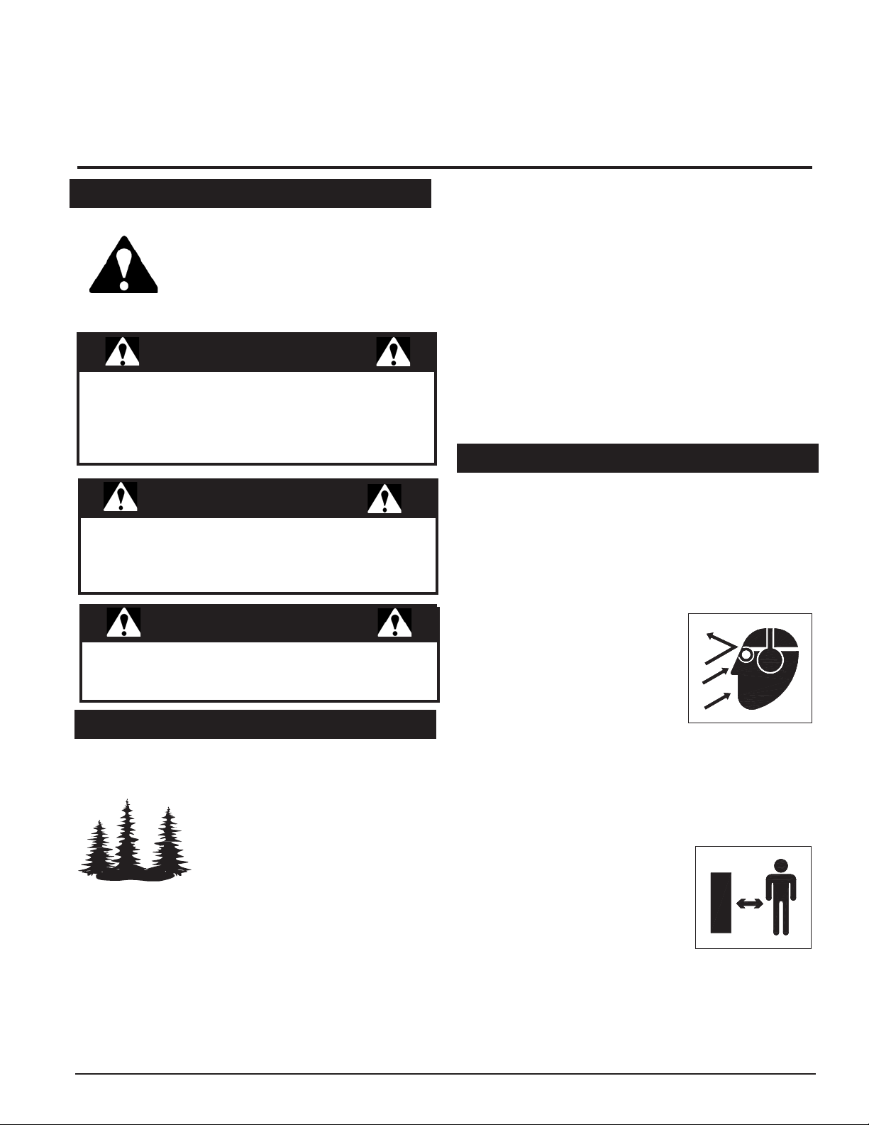
Obtain and wear safety glasses
4.
and use hearing protection at
all times when operating this
machine.
Avoid wearing loose fitted cloth-
5.
ing. Never operate this machine wearing clothing with
drawstrings that could wrap around or get caught in
the machine.
Do not operate this machine if you are under the
6.
influence of alcohol, medications, or substances that
can affect your vision, balance or judgement. Do not
operate if tired or ill. You must
be in good health to operate this
machine safely.
Do not operate this equipment in
7.
the vicinity of bystanders. Keep
the area of operation clear of all
persons, particularly small children. It is recommended that bystanders keep at least
50 feet (15 meters) away from the area of operation.
Do not allow children to operate this equipment.
8.
Use only in daylight or good artificial light.
9.
Do not run this equipment in an enclosed area.
10.
5" and 8" Skid Steer Chipper Owner's Manual
3
Page 6

SAFETY
Engine exhaust contains carbon monoxide gas, a
deadly poison that is odorless, colorless and tasteless.
Do not operate this equipment in or near buildings,
windows or air conditioners.
Always use an approved fuel container. Do not remove
11.
gas cap or add fuel when engine is running. Add fuel
to a cool engine only.
Do not fill fuel tank indoors. Keep open flames, sparks,
12.
smoking materials and other sources of combustion
away from fuel.
Do not operate machine without shields in place. Fail-
13.
ure to do so may cause serious injury or death.
Keep all guards, deflectors, and shields in good work-
14.
ing condition.
Before inspecting or servicing any part of this machine,
15.
shut off the skid steer, disconnect the hydraulics, remove the ignition key and make sure all moving parts
have come to a complete stop.
Check that all screws, nuts, bolts, and other fasteners
16.
are secured, tightened and in proper working condition
before starting the machine and once every 8 hours
of operation.
Do not transport or move machine while the machine
17.
is operating or running.
1.4 OPERATION SAFETY
1.
Always stand clear of discharge area when operating
this machine. Keep face and body away from feed
and discharge openings.
Keep hands and feet out of feed and discharge open-
2.
ings while machine is operating to avoid serious
personal injury. Stop and allow machine to come to a
complete stop before clearing obstructions.
Set up your work site so you are not endangering traffic
3.
and the public. Take great care to provide adequate
warnings.
Do not climb on machine when operating. Keep proper
4.
balance and footing at all times.
Check cutting chamber to verify it is empty before
5.
starting the machine.
The rotor will continue to rotate when clutch is disen-
6.
gaged. Shut off skid steer, disconnect the hydraulics,
remove the ignition key and make sure all moving parts
have come to a complete stop.
Do not insert branches larger than 3 inches in diameter
7.
for the 74500 and 5 inches in diameter for the 74800
into chipper or machine damage may occur.
When feeding material into machine, do not allow
8.
metal, rocks, bottles, cans or any other foreign material
to be fed into the machine.
Ensure debris does not blow into traffic, parked cars,
9.
or pedestrians.
Keep the machine clear of debris.
10.
Do not allow processed material to build up in the dis
11.
charge area. This may prevent proper discharge and can
result in kickback of material through the feed opening.
Shut off machine immediately if the machine becomes
12.
clogged, the cutting mechanism strikes any foreign object,
or the machine starts vibrating or making an unusual
noise. Shut off the skid steer, disconnect the hydraulics,
remove the ignition key and make sure all moving parts
have come to a complete stop. After machine stops:
Inspect for damage.
A.
Replace or repair any damaged parts.
B.
Check for and tighten any loose parts.
C.
On electric start models, disconnect cables from bat-
13.
tery before doing any inspection or service.
Check blade bolts for proper torque after every 8 hours of
14.
operation. Check blades and rotate or resharpen daily or
as required to keep blades sharp. Failure to do so may
cause poor performance, damage or personal injury and
will void the machine warranty.
1.5 FEED ROLLER SAFETY
The feed roller can cause serious injury or death. Keep
1.
hands, feet and clothing away from the feed roller
chipper blades.
Never climb onto the feed chute when the unit is op-
2.
erating or running.
Do not overreach. Keep proper balance and footing
3.
at all times.
Never allow passengers to ride on the feed chute.
4.
When feeding material into the feed roller:
5.
Wear eye, face and hearing protection.
A.
Release material and stand to side of feed chute.
B.
When inspecting or servicing the feed roller, secure
6.
the feed roller in the raised position using the lock-up
pin located on the roller slide.
1.6 MAINTENANCE AND STORAGE SAFETY
Before inspecting, servicing, storing, or changing
1.
an accessory, shut off the skid steer, disconnect the
hydraulics, remove the ignition key and make sure all
moving parts have come to a complete stop.
Replace any missing or unreadable safety decals.
2.
Refer to the parts manual for part numbers when
ordering safety decals from an area dealer.
Allow machine to cool before storing in an enclosure.
3.
Detach the machine from the skid steer and store the
4.
machine out of reach of children and where fuel vapors
will not reach an open flame or spark.
Never store this machine with fuel in the fuel tank
5.
inside a building where fumes may be ignited by an
open flame or spark. Ignition sources can be hot water
and space heaters, furnaces, clothes dryers, stoves,
electric motors, etc.
-
4
5" and 8" Skid Steer Chipper Owner's Manual
Page 7

SAFETY
1.7 SAFETY DECALS
See Section 1.8 for decal locations. Familiarize yourself with all of the safety and operating decals on the machine and the
associated hazards. See the engine owners manual or contact the engine manufacturer for engine safety instructions and
decals. Make certain that all safety and operational decals on this machine are kept clean and in good condition. Refer to the
parts catalog if you need a replacement decal. Decals that need replacement must be applied to their original locations.
1
2
3
PN 12010
PN 13711-00
PN 16085
5
6
7
PN 17423
PN 17837
PN 17846
9
8
PN 14049-00
PN 12589
4
PN 16558
5" and 8" Skid Steer Chipper Owner's Manual
5
Page 8
SAFETY
2
1.8 SAFETY DECAL LOCATIONS
The numbers below correspond to the decals in Section 1.7. Familiarize yourself with all of the safety and operational
decals on the machine and the associated hazards. See the engine owners manual or contact the engine manufacturer
for engine safety instructions and decals. Make certain that all safety and operating decals on this machine are kept
clean and in good condition. Refer to the parts catalog if you need a replacement decal. Decals that need replacement
must be applied to their original locations.
6
5" and 8" Skid Steer Chipper Owner's Manual
Page 9
2
Assembly
Section
WARNING
Before inspecting or servicing any part of this machine,
shut off skid steer, disconnect the hydraulics, remove
ignition key and make sure all moving parts have come
to a complete stop.
IMPORTANT
If any bolts or nuts are dropped in the machine, be
sure to remove them before starting the machine.
Remove items from the shredder area by removing
the discharge screen.
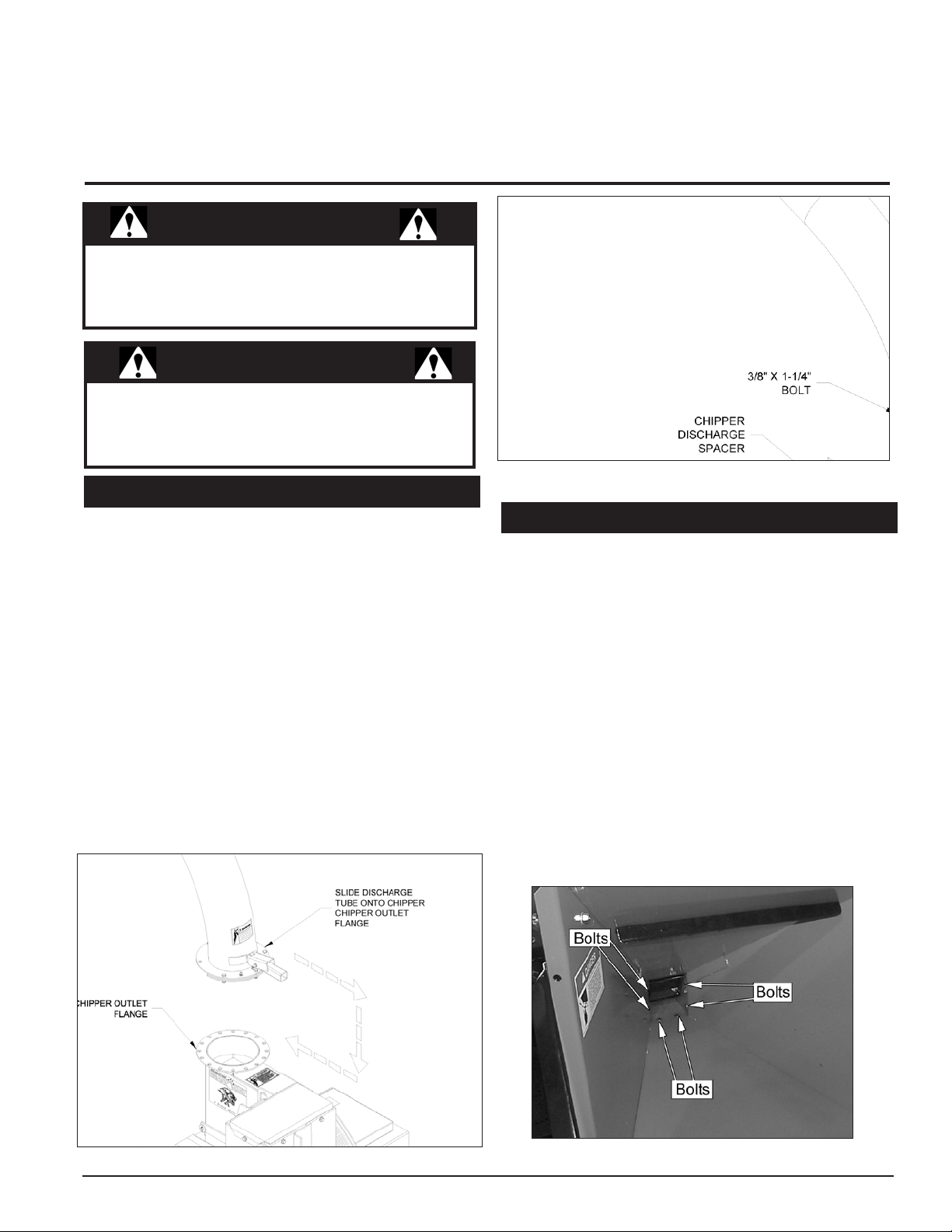
2.1 INSTALLING DISCHARGE TUBE
Remove the skid steer chipper from the shipping pallet.
1.
Lightly grease the chipper outlet flange.
2.
Position the discharge tube over the chipper outlet
3.
flange and slide on using the tube latch (Figure 2.1).
Install the retaining rings with the hardware provided
4.
in the owner's kit (Figure 2.2).
Tighten the bolts so the discharge tube does not rock
5.
on the flange. Do not over tighten the bolts as the
flange will distort.
Lift the latch on the handle of the discharge tube and
6.
position the tube in the desired position.
Release the latch making sure it locks in one of the
7.
holes on the chipper flange.
Add one shot of grease to the grease zerk on the discharge
8.
flange. Rotate the discharge tube to spread grease.
Figure 2.2 - Securing Discharge Tube
2.2 MOUNTING THE CHUTE
2.2.1 MOUNTING THE CHUTE TO THE ROLLER
SUPPORT
The chipper chute must be mounted to the roller support
weldment. On the 74800 the chute is held in place with 8
bolts, on the 74500 the chute is held in place with 6 bolts.
Both models use a chute support.
Place the chute on the roller support weldment. Have
1.
someone assist if necessary.
Align the chute with the mounting holes.
2.
Insert all 6 or 8 (depending on model) 3/8” carriage
3.
bolts into the mounting holes. The 74800 is mounted
with 8 bolts. The 74500 is mounted with 6 bolts. It may
be helpful to align the holes with a punch.
Place washers and nuts on the opposite side of the
4.
bolts and tighten to proper torque.
Figure 2.1 - Attaching Discharge Tube
5" and 8" Skid Steer Chipper Owner's Manual
Figure 2.3 - Mounting the Chute to the Roller Support.
7
Page 10

ASSEMBLY
2.2.2 MOUNTING THE CHUTE SUPPORT:
Make sure the chute is mounted to the roller support
1.
weldment.
Place the chute support underneath the chute.
2.
The side of the chute support with the two mounting
3.
holes is orientated towards the chipper base.
Attach the chipper chute to the base with the provided
4.
3/8” bolts, washers and nuts. It may help to slightly lift
the chipper chute.
Align the other hole of the chipper chute support with
5.
the hole in the chipper chute.
Insert the other 3/8” bolt , washer, and nut. Tighten to
6.
proper torque.
2.3 MOUNTING THE FOUR-POSITION VALVE
Place the 4 position valve on the chipper chute over
1.
the three pre-drilled mounting holes.
From the inside of the chipper chute, using the 5/16”
2.
x 3/4” bolts, and washers, thread the bolts into the
four-position valve.
Tighten 5/16” hardware to proper torque.
3.
Attach the valve control lever according to Figure 2.6.
4.
Tighten the 5/16” bolt to the proper torque.
5.
Figure 2.4 - Mounting the Chipper Chute Support.
Figure 2.5 - Mounting the Four Position Valve.
Figure 2.6
Connecting the Valve Control Lever to the 4 Position Valve.
8
5" and 8" Skid Steer Chipper Owner's Manual
Page 11

3
Section
Features & Controls
FEED ROLLER RATE CONTROL
The feed roller speed is adjustable with a hand crank
located below the chipper feed table. Use a slower feed
roller speed when feeding large branches into the chipper.
Increase the feed roller speed when feeding small branches
into the chipper. Turning the crank counter-clockwise
decreases the feed roller speed. Turning the crank
clockwise increases the feed roller speed.
CONTROL ARM
The control arm has four positions and is used to engage
the feed roller. The four positions are: reverse, stop,
forward, reverse.
5" and 8" Skid Steer Chipper Owner's Manual
DISCHARGE DEFLECTOR
The discharge deflector can be used to aim the spray of
wood chips from the chipper.
DISCHARGE LOCK
The discharge lock serves to lock the rotating discharge
tube. The lock is disengaged by pressing down on the
discharge handle. The discharge tube is then free to pivot.
To engage the lock, release the handle and center the
locking pin on a hole in the chipper outlet flange.
CHUTE EXTENSION TRAY
The chute extension tray is lowered by releasing the
latches. The extension tray then pivots down.
9
Page 12

4
Section
Operation
As with any other piece of outdoor power equipment,
getting the feel for how your machine operates and
getting to know the best techniques for particular jobs are
important to overall good performance.
CHIPPING OPERATION
The chipping operation takes place on the rear of the
machine, where hardened steel chipper blades are
mounted on a rotating rotor assembly. Material fed into
the chipper chute is sliced into small chips and propelled
out through a discharge tube.
WARNING
Before operating your machine, be sure you read and
understand all safety, controls and operating instructions
in this Owner/Operators manual and on your machine.
Failure to follow these instructions can result in serious
injury or property damage.
4.1 HYDRAULIC FLOW RATES
HYDRAULIC FLOW RATES
MINIMUM MAXIMUM
74500 15 gallons/min 22 gallons/min
74800 25 gallons/min 38 gallons/min
Kill the engine and exit the machine to push down the
5.
wedges using the universal skid steer mount levers
(Figures 4.1 and 4.2). On automated models, stay in
the machine and engage the wedges.
WARNING
The wedges must extend through the holes in the
mounting frame of the chipper to securely fasten the
chipper to the universal skid steer mount. Failure to
secure wedges can allow attachment to come off and
cause injury or death.
WARNING
Exceeding the recommended flow rates can cause
severe damage and void the chipper warranty!
4.2 MOUNTING CHIPPER TO SKID STEER
The chipper can be mounted to the skid steer in two
locations. The recommended location is with the feed
chute sitting at the front of the loader. However, if space
is a concern, the unit can be mounted with the feed table
sitting to the left of the machine.
Tilt the universal skid steer mount forward.
1.
Make sure that the wedges are fully raised.
2.
Drive the skid steer forward until the top edge of the
3.
coupler is completely under the top flange on the
chipper.
Tilt the unit backward until the chipper is slightly off
4.
the ground.
10
5" and 8" Skid Steer Chipper Owner's Manual
Figure 4.1 - Connecting the Skid Steer
Figure 4.2 - Securing the Wedges
Page 13

4.3 INSTALL FLUSH FACE COUPLERS
WARNING
Hydraulic lines may be under pressure due to testing
done at the factory.
The skid steer chipper is equipped to attach to flush face
couplers (Figure 4.3). The chipper is shipped with -12 sized
hydraulic couplers fitted on the hoses. A tie wrap is used to
indicate the pressure line. Be sure to connect the hydraulic
hoses to the proper ports.
If the skid steer is fitted with anything other than -12 sized
flush face couplers on the main lines, it will be necessary
to replace the couplers supplied with the chipper.
The chippers are also equipped with a case drain hose. The
case drain is used to eliminate pressure on the chipper’s
hydraulic motor. The motor is rated for 250 to 300 psi of
back pressure.
OPERATION
Most high flow skid steer loaders are equipped with a case drain
line. Standard flow skid steer loaders typically are not. If the
back pressure is over 300 psi, a case drain line will have
to be added. Contact your skid steer dealer for details.
IMPORTANT
NOT ADDING A CASE DRAIN LINE VOIDS THE
CHIPPER WARRANTY!
TO CONNECT:
Before connecting, make sure to relieve the hydraulic
1.
pressure in the skid steer using the skid steer system.
Remove dirt and debris from the surface of the couplers.
2.
Visually check the couplers for damage; replace if
3.
damage is found.
Install the male coupler into the female coupler. Full
4.
connection is made when the ball release sleeve slides
forward on the female coupler.
Turn the sleeve so that it is rotated away from the lock-
5.
ing pin to prevent accidental disconnection.
Repeat the procedure for all hoses, including the
6.
smaller case drain hose.
Figure 4.3 - Installed Couplers
TO DISCONNECT:
Relieve the hydraulic pressure in the skid steer using
1.
the skid steer system.
Rotate the ball sleeve so the grooves are aligned with
2.
the pins in the female coupler.
Retract the sleeve on the female coupler until the
3.
couplers disconnect.
Repeat the procedure for all hoses.
4.
5" and 8" Skid Steer Chipper Owner's Manual
11
Page 14

OPERATION
4.4 HYDRAULIC SCHEMATIC
12
Figure 4.4 - Hydraulic Schematic
5" and 8" Skid Steer Chipper Owner's Manual
Page 15
OPERATION
4.5 PRE-OPERATION
WARNING
Do not attempt to bypass the safety systems of the skid
steer loader.
Wear appropriate eye, face, and hearing protection.
1.
Wear gloves that fit tight against the wrist.
Remove the latch from the side of the feed table.
2.
Lower the chipper feed table.
3.
Check that the feed roller is clear of material.
4.
Place the feed roller control in the “stop” position.
5.
Push down the latch and rotate the discharge chute to
6.
the desired position.
Release the handle and move the chute until it locks
7.
the chute in position.
4.7 STOPPING THE CHIPPER
1.
The operator should disengage the feed roller after all
material has been cleared from the chipper.
The operator should then slow down the engine of the
2.
skid steer to idle and after several seconds disengage
the skid steer hydraulics.
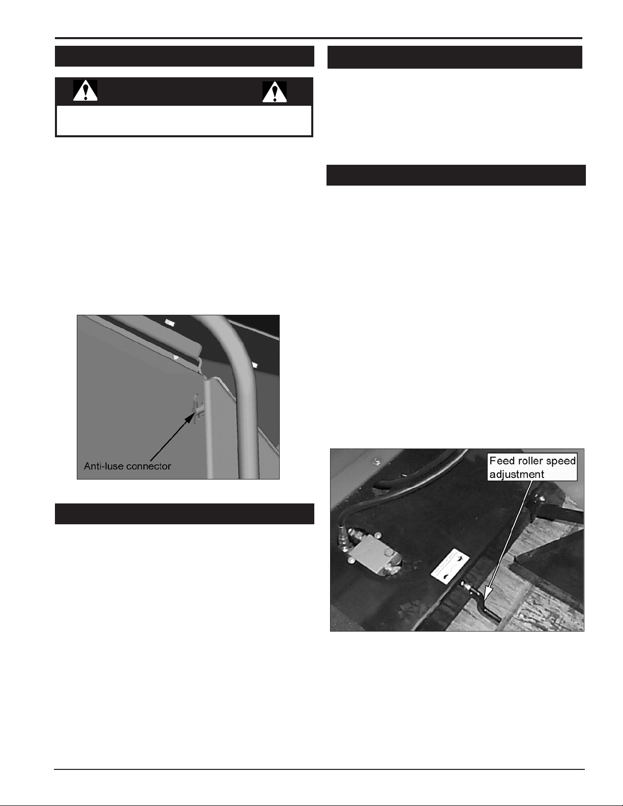
4.8 FEED ROLLER OPERATION
The feed roller control has four positions:
Reverse: Reverses the direction of the feed
A.
roller. Use this function to clear a plugged
feed roller.
Stop: Stops the feed roller.
B.
Forward: Feeds material into the chipper.
C.
Reverse: Reverses the direction of the feed
D.
roller.
The feed roller speed is adjustable with a hand crank located
below the chipper feed table. Use a slower feed roller speed
when feeding large branches into the chipper. Increase the
feed roller speed when feeding small branches into the
chipper. Turning the crank counterclockwise decreases the
feed roller speed. Turning the crank clockwise increases
the feed roller speed.
Figure 4.5 - Anti-Luce Connector
4.6 STARTING THE CHIPPER
Running the skid steer chipper is a one- or two-man
operation. If the system mandates an operator in the
driveseat, two people are needed. The chipper engages
with the hydraulics of the skid steer, as do most skid steer
powered attachments.
Set parking brake.
1.
Ensure the feed roller is in the neutral position.
2.
Engage the hydraulics of the skid steer to supply power
3.
to the unit. The chipper will start to spin.
Place the feed roller in the operating position and bring
4.
the unit up to speed.
The chipper is ready to chip.
5.
5" and 8" Skid Steer Chipper Owner's Manual
Figure 4.6 - Feed Roller Speed Adjustment
13
Page 16
OPERATION
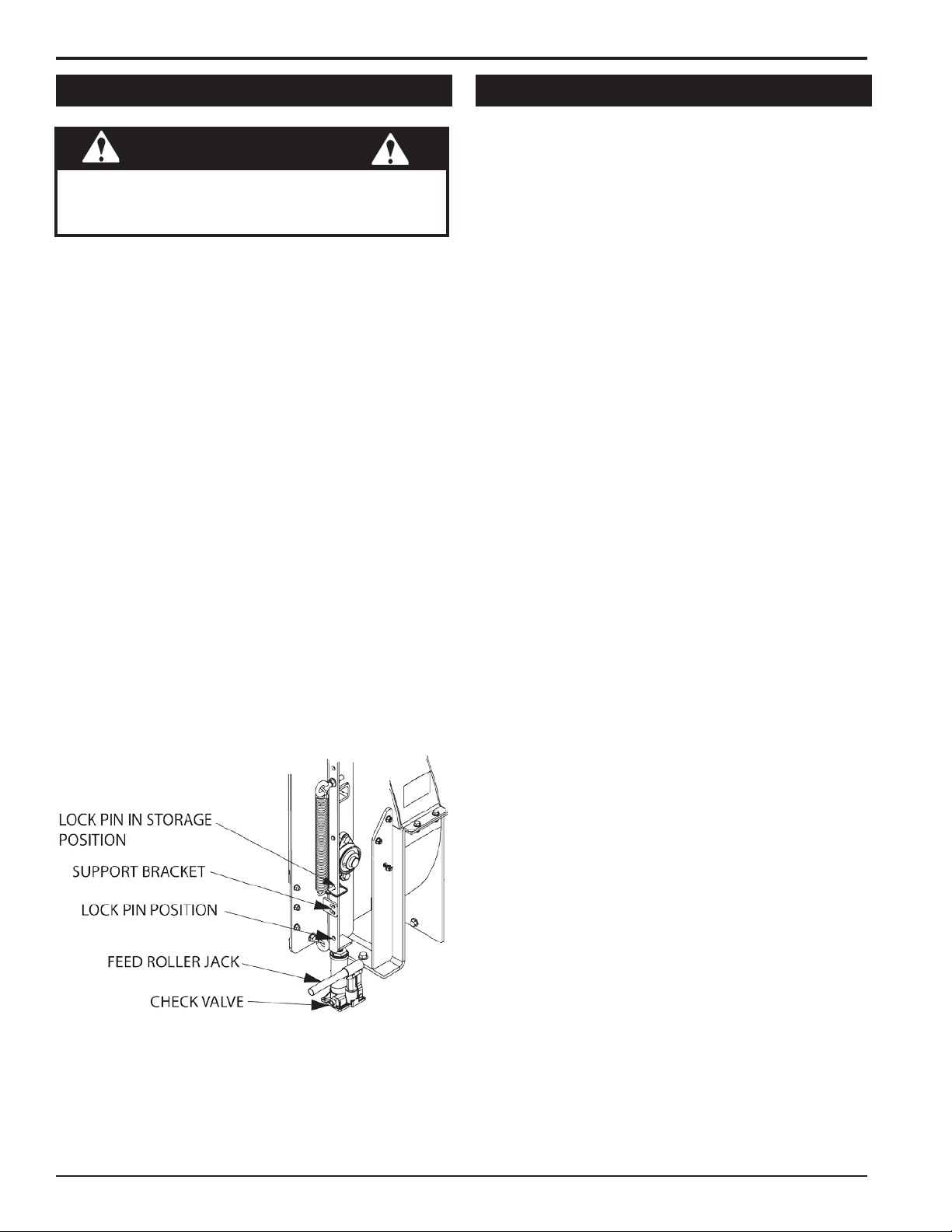
4.9 RAISING THE FEED ROLLER
WARNING
The feed roller must be secured in the up position prior
to servicing the chipper feed area. Failure to do so can
result in serious injury or death.
Before the chipper feed area is serviced, the feed roller
support must be locked in the upright position. To raise the
feed roller, proceed as follows.
Stop skid steer engine, disengage hydraulics, and
1.
allow machine to come to a complete stop.
Turn the check valve located on the bottom of the jack
2.
clockwise, engaging the jack.
Remove the lock pin from its storage position (see
3.
figure below).
Pump the handle to raise the feed roller until the lock
4.
pin position aligns with one of the support bracket
holes.
Secure the position by putting the lock pin through the
5.
support bracket and lock pin position. This will ensure
the feed roller cannot fall from the upright position.
Service or clear the unit of debris.
6.
To lower the feed roller support, remove the lock pin
7.
and then turn check valve counterclockwise to disengage the pump.
Replace lock pin in storage position. LEAVING
8.
THE LOCK PIN IN ANY OTHER POSITION MAY
INTERFERE WITH FEED ROLLER OPERATION.
4.10 CHIPPING GUIDE
The machine chips a variety of materials into a more
readily decomposed or handled condition. The following
guidelines can help you get started.
Run unit at full operating speed before starting to chip
1.
material.
The 74500 is most effective when chipping 3 inch
2.
material. Material that is up to 5 inches in diameter
will fit into the machine, though it may bog the chipper
down. The 74800 is most effective when chipping 5
inch material. Material that is up to 8 inches in diameter
will fit in the machine, though it may bog the chipper
down.
Trim side branches that cannot be bent enough to feed
3.
into the chipper chute. Hold small diameter branches
together in a bundle and feed in simultaneously.
Exclude pieces of metal, rocks, bottles, cans, and
4.
other foreign objects when feeding material into the
machine.
Feed brush from the side of the chipper chute, rather
5.
than from the front. Step aside to avoid being hit by
the brush moving into the chipper.
Do not lean over the chipper chute to push objects
6.
into the cutting device. Use a push stick or brush
paddle.
Never use shovels or forks to feed brush. They can
7.
be chipped, are expensive to replace, and cause
extensive damage. In addition, metal pieces can be
ejected from the chipper chute and cause serious
injury or death.
Never feed brush into the chipper chute with your feet.
8.
14
Figure 4.7 - Feed Roller Lock
5" and 8" Skid Steer Chipper Owner's Manual
Place limb, butt end first, into the chipper chute until
9.
it contacts the chipper blades. The actual feed rate
of the limb into the chipper will depend on the type of
material fed and sharpness of the cutting blades.
Stop the material feeding and allow the engine to
10.
recover if the engine slows to where it may stall.
Remove the branch and rotate it before reinserting it
11.
into the chute if the chipper jams.
Alternately insert and retract the limb or insert continu-
12.
ously at a rate that will not kill the engine.
Chipping dead, dry material will create heat and dull
13.
the chipping blades quickly.
Alternate green material with dry material to lubricate the
14.
chipping blades for longer life and better performance.
The chipping blades will become dull and will require
15.
periodic sharpening. Refer to the Service and Maintenance section for sharpening instructions.
Page 17
5
1/8"
1/4"
Service & Maintenance
Section
5.1 MAINTENANCE SCHEDULE
The items listed in the service and maintenance schedule are to be checked, and if necessary, corrective action taken.
This schedule is designed for units operating under normal conditions. If the unit is operating in adverse or severe usage
conditions it may be necessary for the items to be checked and serviced more frequently.
See engine owners manual for further maintenance and troubleshooting information.
SERVICE AND MAINTENANCE SCHEDULE
FREQUENCY
COMPONENT
NUTS & BOLTS CHECK TORQUE
CHIPPER BLADES
ENTIRE MACHINE CLEAN
ROTOR BEARING GREASE
1
It is a good sign that your chipper blades need sharpening when material stops self feeding.
MAINTENANCE
REQUIRED
CHECK, SHARPEN
IF NEEDED
1
BEFORE
EACH
USE
EVERY
8 HRS
EVERY
25 HRS
EVERY
50 HRS
5.2 CHIPPER BLADES
WARNING
Chipping blades are sharp! Use caution when working
on machine to avoid injury.
The chipper blades will eventually become dull, making
chipping difficult and adding extra strain on the machine.
Poor chipping performance is usually a result of dull chipping
blades. It is recommended that the blades be sharpened
every 5 - 15 hours or if your chipper’s performance has
decreased. Check for the following symptoms and sharpen
the blades if needed.
Severe vibration when feeding material into the chipper.
1.
Small diameter branches do not self-feed.
2.
Chips discharge unevenly or have stringy tails, espe-
3.
cially when chipping green branches.
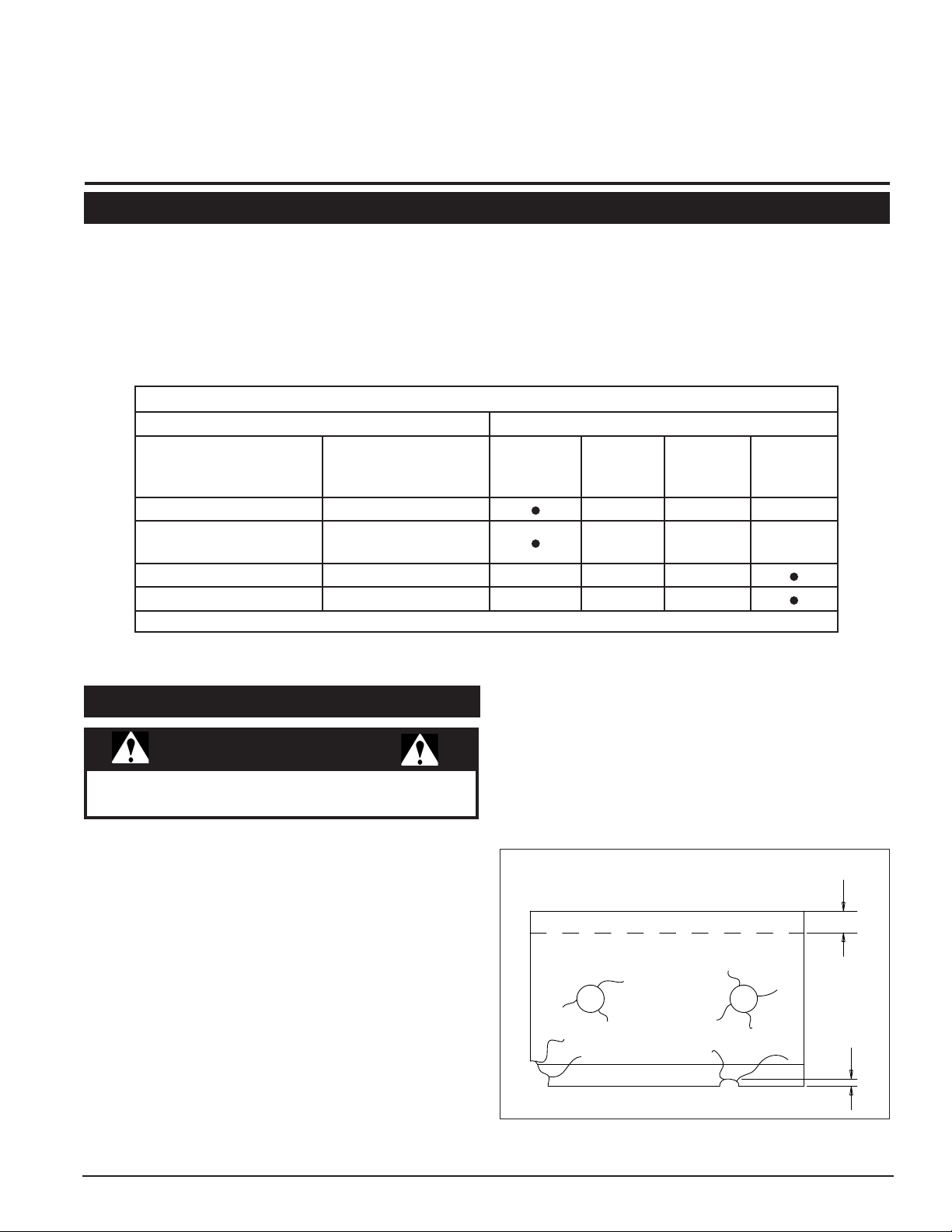
Before you sharpen the chipping blades, check for
permanent damage. Replace the blade if:
There are cracks, broken corners or nicks greater than
1.
1/8" (Figure 5.1).
The base of the cutting edge is worn or has been re-
2.
sharpened so that the edge extends less than 1/16"
above the rotor chipping slot.
Figure 5.1 - Causes for Replacement
5" and 8" Skid Steer Chipper Owner's Manual
15
Page 18
SERVICE & MAINTENANCE
MOUNTING SURFACE
DO NOT GRIND
SHARPENED
SURFACE
SHARPENED
SURFACE
DO NOT GRIND
MOUNTING SURFACE
.25
45˚
MOUNTING SURFACE
DO NOT GRIND
MOUNTING SURFACE
DO NOT GRIND
SHARPENED
SURFACE
SHARPENED
SURFACE
45˚
.38
WARNING
BEFORE INSPECTING OR SERVICING ANY PART OF THIS MACHINE, SHUT OFF POWER SOURCE,
DISENGAGE THE HYDRAULICS AND MAKE SURE ALL MOVING PARTS HAVE COME TO A COMPLETE STOP.
5.3 REMOVING THE BLADES 5.4 SHARPENING THE BLADES
Disconnect the hydraulic hoses from the skid steer.
1.
Position the discharge chute to the side of the chipper.
2.
Remove the two bolts on the chipper housing.
3.
Tip the chute and housing away from the chipper to
4.
expose the rotor and the blades.
Use a pry bar between two of the fan blades to prevent
5.
the chipper from rotating during blade removal and
installation.
Remove the blades making sure not to slip the wrench,
6.
the chipper blades are sharp.
The chipper blades are reversible. If the blades have
7.
not been reversed, flip the blades 180 degrees and
reinstall.
If the chipper blades need to be sharpened refer to
8.
Section 5.4 of the manual.
Inspect all components of the chipper for damage and
9.
replace if necessary.
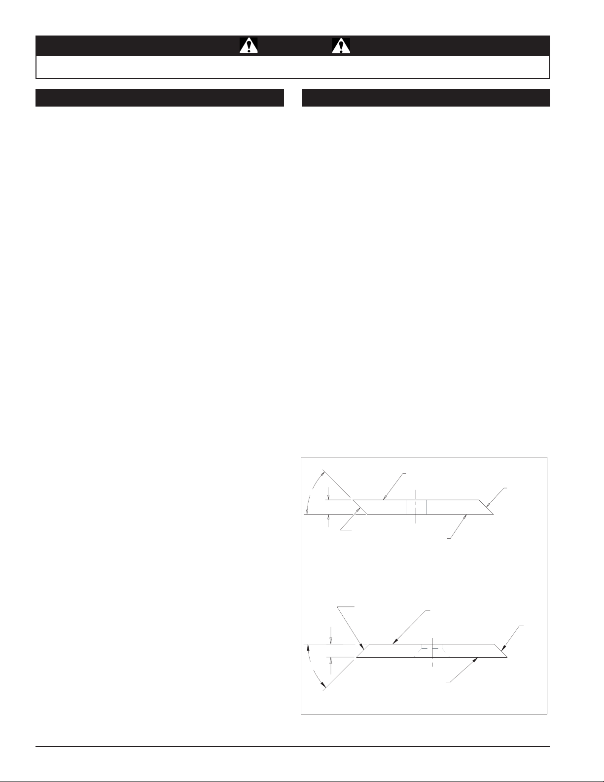
Never sharpen or grind the mounting surfaces of the
•
blades. This will cause the edge to roll and the blade will
be damaged, resulting in poor chipping performance.
Regrind the angled edge of the chipping blades to 45
•
degrees (Figure 5.2).
The blades can be ground on a bench grinder or by
•
a professional.
Make sure some type of fixture is used to correctly hold
•
the blade at the proper angle.
Be careful when grinding so that the blade does not
•
become overheated and change color. This will remove
the heat-treated properties.
Use short grinding times and cool with water or some
•
type of liquid coolant.
Remove an equal amount off each blade to maintain
•
rotor balance.
Small imperfections such as nicks and burrs on the
•
flat side of the blade will not affect the chipping performance of the machine.
For blades that have been repeatedly sharpened,
•
ensure that the sharpened surface extends past the
chipping slot opening. If it does not extend past the
opening, the blades should be replaced.
Model 74500
16
5" and 8" Skid Steer Chipper Owner's Manual
Figure 5.2 - Double Edged Blade
Model 74800
Page 19

SERVICE & MAINTENANCE
WARNING
BEFORE INSPECTING OR SERVICING ANY PART OF THIS MACHINE, SHUT OFF POWER SOURCE,
DISENGAGE THE HYDRAULICS AND MAKE SURE ALL MOVING PARTS HAVE COME TO A COMPLETE STOP.
5.5 INSTALLING THE BLADES
Remove any accumulated material from the blade
1.
pocket and the bottom of the chipper blade.
Reinstall the chipper blades and tighten the bolts to a
2.
torque of 25 Ft-lbs. (74500) or 120 Ft-lbs. (74800).
Check the blade/anvil clearance and adjust if necessary.
3.
Close the chipper housing and secure with removed
4.
bolts to a torque of 25-28 Ft-lbs.
Reconnect machine hydraulics.
5.
5.6 SETTING BLADE CLEARANCE
The chipping blades should clear the anvil by 1/16 to 1/8
inch. To adjust the blade clearance, proceed as follows:
Adjust the anvil by loosening the two (74500) or three
1.
(74800) anvil bolts.
On the 74500, move the anvil assembly in or out by
2.
turning the nuts on the block adjuster weldment.
On the 74800, with the three anvil bolts loosened,
3.
adjust the anvil to the desired position.
If the anvil cannot be moved to specifications due to
4.
wear, rotate the anvil or replace the anvil.
Secure all hardware and adjust to torque.
5.
WARNING
It is important to ensure that the minimum gap between
the chipping anvil and ALL chipping blades is 1/16". All
chipping blades should be rotated until even with the
chipping anvil and then measured. Failure to do so
can result in the chipping blades striking the chipping
anvil causing serious injury or death.
5.7 CLEARING A PLUGGED ROTOR
The feed roller lift jack is used to raise the feed roller if
chipping material becomes wedged in or behind the feed
roller. Raise the feed roller and the chipper housing to
safely remove the material.
Stop skid steer engine, disengage hydraulics, and
1.
allow machine to come to a complete stop.
Position the chipper chute to the side of the chipper.
2.
Remove the two bolts on the chipper blade access
3.
cover.
Tip the cover away from the chipper to expose the
4.
rotor and the blades.
Turn the check valve located on the bottom of the jack
5.
clockwise, engaging the jack.
Remove the lock pin from its storage posistion (see
6.
figure below).
Pump the handle to raise the feed roller until the lock
7.
pin position aligns with one of the support bracket
holes.
Secure the position by putting the lock pin through the
8.
support bracket and lock pin position. This will ensure
the feed roller cannot fall from the upright position.
Clear the unit of debris.
9.
To lower the feed roller support, remove the lock
10.
pin and then turn check valve counterclockwise to
disengage the pump.
Replace lock pin in storage position. LEAVING
11.
THE LOCK PIN IN ANY OTHER POSITION MAY
INTERFERE WITH FEED ROLLER OPERATION.
Lower access cover and reattach the two bolts.
12.
Figure 5.3 - Anvil and Chipper Blade Clearance
5" and 8" Skid Steer Chipper Owner's Manual
Figure 5.4 - Feed Roller Lock
17
Page 20

SERVICE & MAINTENANCE
WARNING
BEFORE INSPECTING OR SERVICING ANY PART OF THIS MACHINE, SHUT OFF POWER SOURCE,
DISENGAGE THE HYDRAULICS AND MAKE SURE ALL MOVING PARTS HAVE COME TO A COMPLETE STOP.
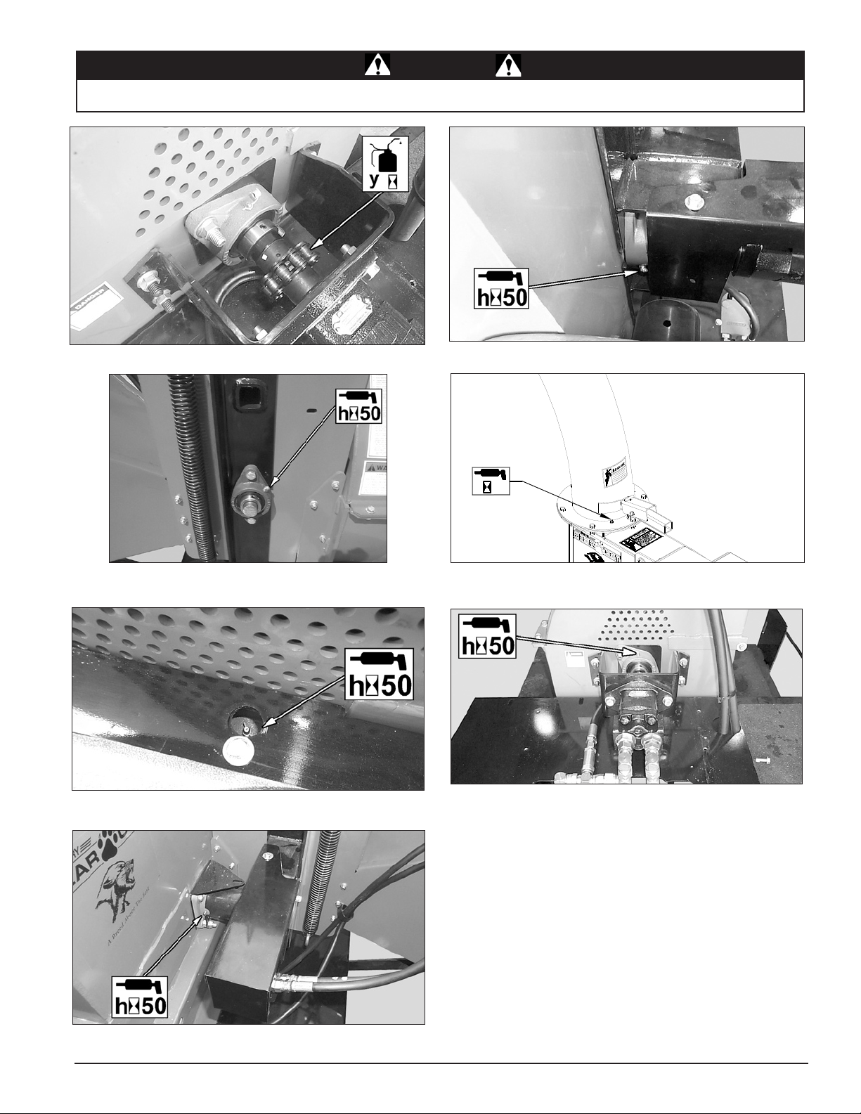
5.8 GREASING BEARINGS AND PIVOTS
Mounted bearings are pre-lubricated at our factory and are
ready for operation.
LUBRICATION: Lubrication of bearings is determined by
operating conditions and environment. Lubricate standard
bearings with a LITHIUM based grease.
GREASING INTERVALS: Bearings in extreme environments
will require more frequent greasing intervals.
GREASE FILL AMOUNTS: It is preferred that experience
dictate fill amounts due to wide variances in applications,
greasing equipment and operating conditions. The
quantities shown in the pictures are recommended
amounts. In most cases, it is best to lube in small amounts,
under low pressure, until a thin bead of fresh grease is
visible at the seal lip area.
Care should be taken when greasing bearings to avoid
overfilling. Overfilling can lead to excessive heat and or
unsealing of the seals. Grease should be introduced in
small increments and under light pressure. Whenever
possible, the bearing should be rotated slowly while grease
is being added to ensure equal distribution throughout the
raceways.
The chipper models described in this manual have several
bearings and pivots that require greasing. Refer to figures
5.5 to 5.11 for greasing intervals and quantities.
NOTE
Polyuria and lithium based greases are not compatible.
Mixing the two grease types may lead to premature
failure.
NOTE
The use of pneumatic grease equipment is not
recommended unless low pressure is assured.
18
5" and 8" Skid Steer Chipper Owner's Manual
Page 21
SERVICE & MAINTENANCE
h
50
WARNING
BEFORE INSPECTING OR SERVICING ANY PART OF THIS MACHINE, SHUT OFF POWER SOURCE,
DISENGAGE THE HYDRAULICS AND MAKE SURE ALL MOVING PARTS HAVE COME TO A COMPLETE STOP.
Figure 5.5 - Oil Yearly Figure 5.6 - Grease every 50 Hours
Figure 5.7 - Grease every 50 Hours
Figure 5.9 - Grease every 50 Hours
Figure 5.8 - Grease every 50 Hours
Figure 5.10
Same Zerk as Figure 5.8, shown with Shield Removed.
Figure 5.11 - Grease every 50 Hours
5" and 8" Skid Steer Chipper Owner's Manual
19
Page 22

6
Troubleshooting
Section
Before performing any of the corrections in this troubleshooting chart, refer to the appropriate information contained in
this manual for the correct safety precautions and operating or maintenance procedures. Contact your nearest dealer
or the factory for service problems with the machine.
PROBLEM POSSIBLE CAUSE REMEDY
1.
Reverse or sharpen blades.
Dull chipper blades.
Hard to feed chipper.
Feed roller does not engage.
Excessive vibration while
running.
1.
Obstructed discharge.
2.
Improper blade clearance.
3.
Low hydraulic flow due to low
1. Move loader engine speed to higher
engine RPM.
Chipper not correctly attached to
1.
skid steer.
Damaged chipper blades.
2.
Use branch or similar object to clear dis-
2.
charge.
Adjust clearance between chipper block
3.
and chipper blades.
1.
RPM.
Check for correct mounting of the chipper
1.
to the skid steer.
Replace damaged blades.
2.
Rotor will not turn.
Does not discharge chips.
Chipper does not seat
properly on the skid steer.
No hydraulic flow.1.
Not enough hydraulic flow.1.
Wedges are not fully extended.
1.
Mud, dirt or stones are lodged
2.
between the chipper and the skid
steer.
Check quick couplers connection. Check
1.
for damaged hose ends and fittings.
Make sure enough flow is provided by the
1.
skid steer.
Retract wedges.
1.
Remove debris from between the chipper
2.
and the skid steer.
20
5" and 8" Skid Steer Chipper Owner's Manual
Page 23

7
"H"
"A"
"I"
"C"
"E"
"F"
"B"
"D"
"G"
Specifications
Section
7.1 SIZE SPECIFICATIONS
MODEL 74500 & 74800 DIMENSIONAL DATA
MODEL A B C D E F G H I
74500 91.9 102.2 56.4 46.0 48.1 49.2 23.3 29.6 6.0
74800 92.2 103.3 59.6 46.0 45.4 56.5 23.6 37.8 8.0
ROTOR SPEED 2000 RPM AT 15 GPM 1500 RPM AT 25 GPM
FRAME MATERIAL 1/4" THICK STEEL CONSTRUCTION 1/4" THICK STEEL CONSTRUCTION
CHUTE SIZE
DRIVE SYSTEM HYDRAULICS HYDRAULICS
SKID-STEER HYDRAULICS STANDARD OR HIGH-FLOW HIGH-FLOW
CHIPPER BLADES 4 BLADES (TOOL STEEL) 4 BLADES (TOOL STEEL)
ROTOR SIZE 20" X 1-1/4", 140 POUNDS 30" X 1-1/4", 275 POUNDS
WEIGHT 1145 LBS. 1525 LBS.
CHIPPER OPENING SIZE*
CONTINUOUS CHIPPING SIZE* 3" (76.2 MM) DIAMETER 5" (127 MM) DIAMETER
DISCHARGE TUBE ROTATING ANGLE RANGE 360 DEGREES 360 DEGREES
*CONTINUOUS CHIPPING SIZE RATING REFERS TO THE SUGGESTED FEEDING SIZE OF LIMBS FOR NORMAL OPERATIONS.
LIMBS UP TO THE CHIPPER OPENING SIZE MAY BE FED, BUT DECREASED PERFORMANCE WILL OCCUR.
5" and 8" Skid Steer Chipper Owner's Manual
SPECIFICATIONS
32" X 36" 32" X 36"
5-1/2" X 7" 9" X 9"
21
Page 24

SPECIFICATIONS
A
SAE - 2
SAE - 5
SAE - 8
A
4.8
8.8
10.9
12.9
7.2 BOLT TORQUE
The tables below are for reference purposes only and their use by anyone is entirely voluntary, unless otherwise noted.
Reliance on their contents for any purpose is at the sole risk of that person and any loss or damage resulting from the
use of this information is the responsibility of that person.
ENGLISH
BOLT DIAMETER
(A)
1/4" 7.5 5.5 11 8 16 12
5/16" 15 11 23 17 34 25
3/8" 27 20 41 30 61 45
7/16" 41 30 68 50 95 70
1/2" 68 50 102 75 149 110
9/16" 97 70 149 110 203 150
5/8" 122 90 203 150 312 230
3/4" 217 160 353 260 515 380
7/8" 230 170 542 400 814 600
1" 298 220 786 580 1220 900
1-1/8" 407 300 1085 800 1736 1280
1-1/4" 570 420 2631 1940 2468 1820
SAE 2 SAE 5 SAE 8
N.m Ft-lb. N.m Ft-lb. N.m Ft-lb.
BOLT TORQUE *
* Torque value for bolts and capscrews
are identified by their head markings.
Torque figures indicated above are valid
for non-greased or non-oiled threads
and heads unless otherwise specified.
Therefore, do not grease or oil bolts or
capscrews unless otherwise specified
in this manual. When using locking
elements, increase torque values by
5%.
METRIC
BOLT DIAMETER
(A)
M3 0.5 0.4 - - - - - -
M4 3 2.2 - - - - - -
M5 5 4 - - - - - -
M6 6 4.5 11 8.5 17 12 19 14.5
M8 15 11 28 20 40 30 47 35
M10 29 21 55 40 80 60 95 70
M12 50 37 95 70 140 105 165 120
M14 80 60 150 110 225 165 260 190
M16 125 92 240 175 350 255 400 300
M18 175 125 330 250 475 350 560 410
M20 240 180 475 350 675 500 800 580
M22 330 250 650 475 925 675 1075 800
M24 425 310 825 600 1150 850 1350 1000
M27 625 450 1200 875 1700 1250 2000 1500
LOCATION ON MACHINE HARDWARE DESCRIPTION
74500 CHIPPER BLADE MOUNTING BOLTS 5/16" X 1-1/4" HEX HD GRADE 8 BOLTS (QTY 8) 25 FT-LBS.
74800 CHIPPER BLADE MOUNTING BOLTS 1/2" X 2-1/2" FLAT HD SKT. (QTY 12) 75 FT-LBS.
4.8 8.8 10.9 12.9
N.m Ft-lb. N.m Ft-lb. N.m Ft-lb. N.m Ft-lb.
BOLT TORQUE *
SPECIAL TORQUE REQUIREMENTS
TORQUE
(UNIFIED INCH)
TORQUE
(METRIC)
27 N.m
101 N.m
22
5" and 8" Skid Steer Chipper Owner's Manual
Page 25

Page 26

Page 27

Page 28

CRARY INDUSTRIES
237 12th St. NW • P.O. Box 849
West Fargo, ND 58078-0849
PH: (701)282-5520 • FAX: (701)282-9522
E-mail: sales@BearCatProducts.com
www.BearCatProducts.com
Manufactured in the
United States of America
by Crary Industries
 Loading...