

Page 1

OWNER
OPERATORS
MANUAL
Towable Truck
Loader
Models
75124
24 HP Truck Loader
73724
24 HP Truck Loader
Skid Mount
Crary Company
A Division of TerraMarc Industries
237 12th St. NW • P.O. Box 849
West Fargo, ND 58078-0849
(701)282-5520 • FAX: (701)282-9522
www.bearcatproducts.com
www.terramarc.com
Manual P/N 13991-00
Rev. 10/01
Page 2

Before you Begin
DEAR BEAR CAT CUSTOMER,
Thank you for purchasing a Crary Bear Cat product. The Bear Cat line is designed, tested, and
manufactured to give years of dependable performance. To keep your machine operating at
peak efficiency, it is necessary to adjust it correctly and make regular inspections. The following
pages will assist you in the operation and maintenance of your machine. Please read and
understand this manual before operating.
If you have any questions or comments about this manual, please call us toll-free at 1-800-247-
7335.
If you have any questions or problems with your machine, please call or write your local
factory-authorized Bear Cat dealer.
PLEASE SEND US YOUR WARRANTY CARD
A warranty card is included in your owner's kit packaged with your machine. Please take the
time to fill in the information requested on the card. When you send your completed card to us,
we will register your machine and start your coverage under our limited warranty.
How to Contact
Bear Cat
A
DDRESS
Crary Bear Cat
237 NW 12th Street
PO Box 849
West Fargo, ND 58078
P
HONE
800-247-7335
701-282-5520
Fax: 701-282-
9522
E
MAIL
opesales@crary.com
service@crary.com
H
OURS
EMISSION INFORMATION
WARNING
WARNING TO ALL CALIFORNIA
AND OTHER STATES OPERATING
OUTDOOR POWER EQUIPMENT
Under California Law and under the
laws of several other states you are
not permitted to operate an internal
combustion engine using hydrocarbon
fuels on any forest covered, brush
covered or grass covered land or on
land covered with grain hay or other
flammable agricultural crop, without an
engine spark arrester in continuous
effective working order.
The engine on your power equipment,
like most outdoor power equipment, is
an internal combustion engine that
burns gasoline, a hydrocarbon fuel.
Therefore, your power equipment must
be equipped with a spark arrester
muffler in continuous effective working
order. The spark arrester must be
attached to the engine exhaust system
in such a manner that flames or heat
from the system will not ignite
flammable material.
Failure of the owner/operator of the
equipment to comply with this
regulation is a misdemeanor under
California law, and may also be a
M-F, 8 a.m. to 5
p.m. Central Time
violation of other state and or federal
regulations, laws, ordinances, or
codes. Contact your local fire marshal
or forest service for specific information
about what regulations apply in your
area.
The standard muffler installed on the
engine is not equipped with a spark
arrester. One must be added before
use if this machine is intended to be
used in an area where a spark arrester
is required by law. Contact the local
authorities if these laws apply to you.
See your authorized engine dealer for
spark arrester options.
I
Truck Loader Operator’s Manual
Page 3

Limited Warranty
Crary Bear Cat Truck Loaders are warranted for 1 year from date of sale for consumers and commercial or
rental operations.
Within the above stated period, Crary Co. will replace any part(s) found to be defective in material and/or
workmanship, after the receipt of the part in our plant. Labor costs to replace these defective parts will be
paid at a Crary established labor rate and time allowed (flat rate) for repair. All transportation charges
incurred in shipping part(s) are the responsibility of the purchaser.
This warranty is void in the case of accidents, failure to perform normal maintenance, or failure to follow
those instructions listed in the service manual. This warranty is also in lieu of all other expressed warranties
and voids any implied warranty as to the merchantability or fitness of the product for a particular purpose
and of any other obligation on the part of Crary Co. Some states do not allow limitations on how long the
implied warranty lasts, so the above limitation may not apply to you.
This warranty applies only to parts or components that are defective, and does not cover necessary repair
due to normal wear, misuse, accidents, or lack of proper maintenance. This includes belts, pulleys, and
chipper blades. Regular routine maintenance of the unit to keep it in proper operating condition is the
responsibility of the owner.
All warranty repair reimbursable under the Crary Co. warranty must be performed by an authorized Bear
Cat service dealer using Bear Cat approved replacement parts. Repair or attempted repair by anyone other
than an authorized Bear Cat service dealer is not reimbursable under the Crary Co. warranty. In addition,
these unauthorized repair attempts may result in additional malfunction, the correction of which is not
covered by warranty.
Crary Co. is not liable for indirect, incidental, or consequential damages in connection with the use of this
product including any cost or expense or providing substitute equipment or service during periods of
malfunction or non-use.
Some states do not allow the exclusion of incidental or consequential damages, so the above exclusion
may not apply to you. This warranty gives you specific legal rights. You may also have other rights that
vary from state to state.
Be sure to note the serial number in any correspondence with Crary Co. or any authorized Bear Cat dealer.
Crary Company
A Division of TerraMarc Industries
237 12th St. NW • P.O. Box 849
West Fargo, ND 58078-0849
(701)282-5520 • FAX: (701)282-9522
www.bearcatproducts.com
www.terramarc.com
Truck Loader Operator’s Manual II
Page 4

Contents
Section Description Page
SERIAL NUMBER DECAL LOCATION ........................................................................................................ 1
SAFETY .................................................................................................................................... 2
1.1 THE SAFETY ALERT SYMBOL ............................................................................ 2
1.2 BEFORE OPERATING .......................................................................................... 2
1.3 BEFORE OPERATING .......................................................................................... 3
1.4 OPERATION SAFETY ........................................................................................... 3
1.5 MAINTENANCE AND STORAGE SAFETY ............................................................ 4
1.6 TOWING SAFETY ................................................................................................. 4
1.7 BATTERY SAFETY ............................................................................................... 4
ASSEMBLY .................................................................................................................................... 5
2.1 ASSEMBLY DIAGRAM.......................................................................................... 5
2.2 ATTACHING THE HITCH ........................................................................................ 6
2.3 ATTACH THE TRAILER WHEELS ......................................................................... 6
2.4 ATTACHING THE VACUUM HOSE TO THE HOSE SUPPORT .............................. 6
2.5 ATTACH THE BLOWER DISCHARGE TUBE ......................................................... 6
2.6 INSTALLING THE BATTERY .................................................................................. 7
OPERATION .................................................................................................................................... 8
3.1 STARTING INSTRUCTIONS: 24 HP ENGINE ........................................................ 8
3.2 VACUUMING ......................................................................................................... 8
3.3 STOPPING ............................................................................................................ 8
3.4 UNPLUGGING ....................................................................................................... 8
SERVICE AND MAINTENANCE .................................................................................................................. 9
4.1 SERVICE AND MAINTENANCE SCHEDULE ........................................................ 9
4.2 DRIVE BELT .......................................................................................................... 9
4.3 FLEX HOSE REPLACEMENT ............................................................................... 9
4.4 TRAILER SERVICE ............................................................................................... 9
4.5 ENGINE MAINTENANCE ..................................................................................... 10
4.6 OIL CHANGING INFORMATION........................................................................... 10
4.7 REFUELING INFORMATION ................................................................................ 10
TROUBLESHOOTING ............................................................................................................................... 11
5.1 GENERAL TROUBLESHOOTING ........................................................................ 11
SPECIFICATIONS .................................................................................................................................. 12
6.1 TRUCK LOADER SPECIFICATIONS .................................................................... 12
6.2 TOWABLE DIMENSION DIAGRAM ..................................................................... 13
6.3 SKID MOUNT DIMENSION DIAGRAM ................................................................. 14
6.4 BOLT TORQUE .................................................................................................. 15
III
Truck Loader Operator’s Manual
Page 5
SERIAL NUMBER LOCATION
Always give your dealer the serial number of your Crary Bear Cat product when ordering parts, requesting service or any
other information.
Please record the serial number in the space provided below and on the warranty and registration card.
SERIAL NUMBER DECAL LOCATION
WARNING
To prevent personal injury or property damage: Disengage the source providing power to the machine and
make sure that all moving parts have come to a complete stop, before obtaining serial number, servicing,
adjusting or repairing.
Serial Number Decal
Fig. #1, Serial number decal location
YXXXXX
Serial Number ________________________
Fig. #2, Serial number decal
REPLACEMENT PARTS
Only genuine Bear Cat replacement parts should be used to repair the machine. Bear Cat replacement parts are available
from your Bear Cat dealer. To obtain prompt, efficient service, remember to give the dealer the correct part description and
serial number of the machine.
Please be sure to provide the following information:
1. The SERIAL NUMBER of your machine.
2. The PART NUMBER of the part.
3. The PART DESCRIPTION.
4. The QUANTITY needed.
Page 1Truck Loader Operator’s Manual
Page 6
Safety
1
Section
1.1 THE SAFETY ALERT SYMBOL
This is the safety alert symbol. It is used in this Owner / Operator’s Manual and on your machine
to alert you to potential hazards.
Whenever you see this symbol, read and obey the safety message that follows it. Failure to obey
the safety message could result in personal injury, death or property damage.
Indicates an imminently hazardous situation that, if not avoided, will result in
DANGER
WARNING
CAUTION
death or serious injury.
Indicates a potentially hazardous situation that, if not avoided, could result in
death or serious injury.
Indicates a potentially hazardous situation that, if not avoided, may result in
minor or moderate injury.
1.2 BEFORE OPERATING
1. Read this Owner / Operator’s
manual. Be completely familiar
with the controls and the proper
use of this equipment.
2. Before inspecting or servicing any
part of the machine, wait for all
parts to stop moving. Be aware that
rotating parts slow down gradually
after power is stopped.
3. Keep safety decals clean and legible. Replace missing or illegible
safety decals.
4. Familiarize yourself with all of the
safety and operating decals on this
equipment and on any of it’s attachments or accessories.
5. Do not allow children or any person unfamiliar with the use of the
unit to use this machine.
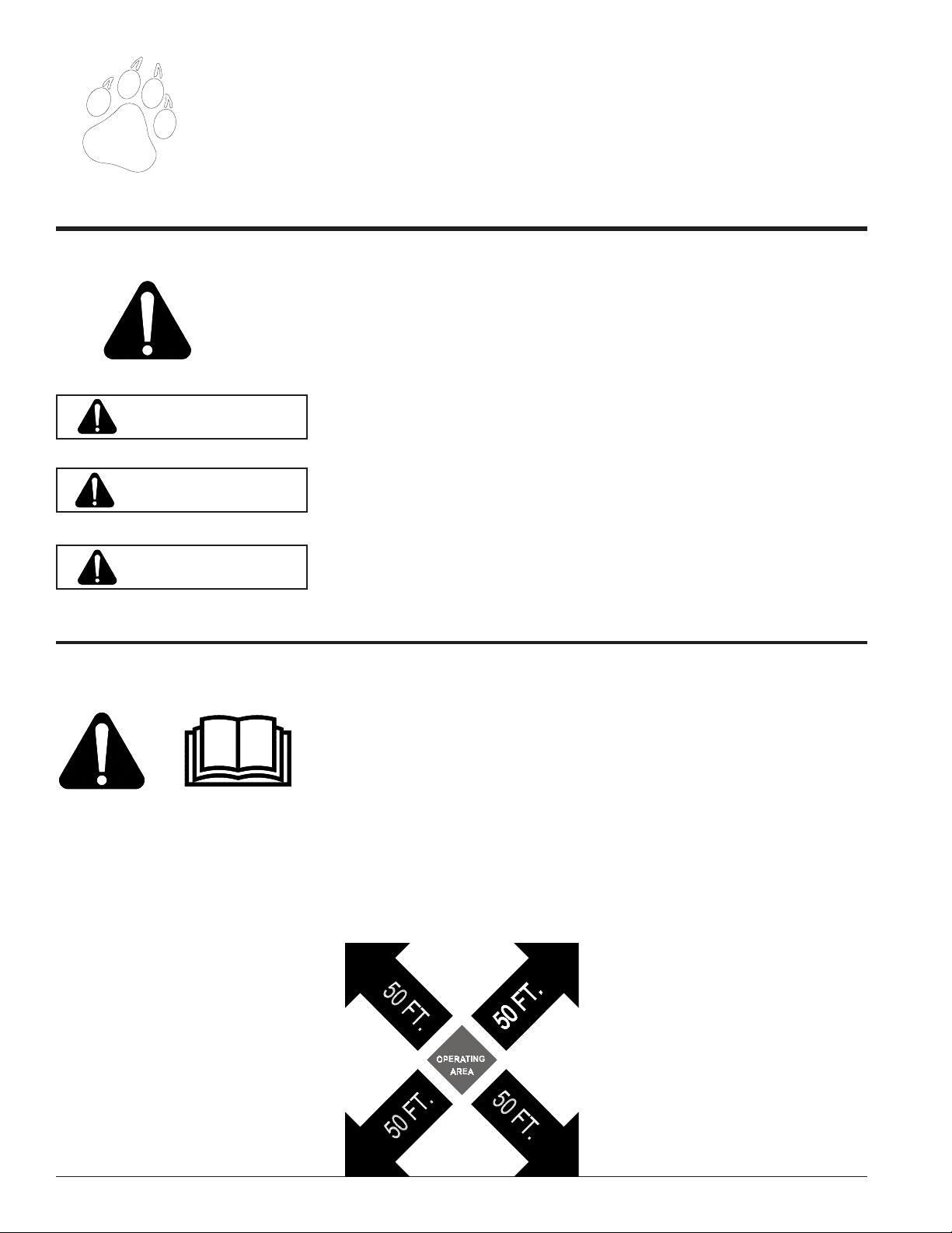
6. Keep the area of operation clear of
all persons, particularly small children. Keep bystanders at least
50 feet (15 meters) away from the
area of operation.
7. Do not run this equipment in an
enclosed area. Do not operate this
equipment in or near buildings,
windows, or air conditioners.
8. If needed, always use an approved
fuel container. Keep open flames,
sparks, smoking materials, and
other sources of combustion away
from fuel.
9. Do not operate this machine if you
are under the influence of alcohol,
medications, or substances that
can affect your vision, balance, and
judgement. Do not operate if tired
or ill. You must be in good health
to operate this machine safely.
Page 2 Truck Loader Operator’s Manual
Page 7

1.3 BEFORE OPERATING
10. Use only in daylight or good artificial light.
11. Wear safety glasses at all times
while operating this machine.
12. Never use without proper guards
in place.
13. Avoid wearing loose fitting clothing. Never operate this machine
wearing clothing with drawstrings
that could wrap around or get
caught in the machine.
Safety
other fasteners for proper tightness
to ensure everything is in proper
working condition once every 10
hours of operation.
15. Keep all guards, deflectors, and
shields in place and in good working condition.
1.4 OPERATION SAFETY
WARNING
Material can kickup or shift suddenly
and cause serious injury or death.
Wear eye and hearing protection.
DANGER
Keep hands, feet and clothing out of
inlets and discharge openings while
machine is operating to avoid serious personal injury.
14. Check that all screws, nuts, bolts,
and other fasteners are properly secured before starting the machine.
Check all screws, nuts, bolts, and
1. Do not allow hands or any part of
body or clothing near any moving
part.
2. Stand clear of the discharge area
when operating this machine.
3. Do not climb on machine when
operating. Keep proper balance
and footing at all times.
4. Keep the machine clear of debris
and other accumulations.
16. Do not transport or move machine
while the engine is running.
5. Set up your work site so you are
not endangering traffic and the public. Take great care to provide adequate warnings.
6. Ensure debris does not blow into
traffic, parked cars, or pedestrians.
7. Check the bolts for correct torque
every 10 hours of operation.
8. Shut off engine and allow machine
to stop completely before clearing
debris if the machine becomes
clogged.
Page 3Truck Loader Operator’s Manual
Page 8

Safety
1.5 MAINTENANCE AND STORAGE SAFETY
NOTE
If equipped, see engine owners
manual or contact the engine manufacturer for engine safety instructions and decals.
1.6 TOWING SAFETY
1. Replace any missing or unreadable safety decals. Refer to the
parts manual for part numbers
when ordering safety decals from
an area Bear Cat dealer.
2. Store the machine out of reach of
children and where potential fuel
vapors will not reach an open flame
or spark.
3. Allow machine to cool before storing in an enclosure.
1. Rotate the discharge tube to face
the opposite direction of the towing vehicle before towing. This prevents the discharge tube from projecting over the trailer wheels and
striking foreign objects.
2. Connect hitch safety chains.
Tighten and secure trailer hitch
bolts. Do not attempt to tow the
trailer if vehicle is not equipped with
a 2” ball.
1.7 BATTERY SAFETY
1. Improper use and care of the battery on electric start models can
result in serious personal injury or
property damage. Always observe
the following safety precautions:
2. Poison/Danger - Causes severe
burns. The battery contains sulfuric acid. Avoid contact with skin,
eyes or clothing. Keep out of
reach of children.
ANTIDOTE-External Contact:
Flush immediately with lots of water.
3. Do not exceed maximum towing
speed, indicated on tire sidewall.
Inflate tires to manufacturers specs
as stated on the tire sidewall.
4. Check wheel lug bolts periodically
to ensure they are tight and secure.
5. Make sure the jack stand on trailer
is in the UP position to clear the
ground during towing. Place the
3. The battery produces explosive
gases. Keep sparks, flame or
cigarettes away. Ventilate area
when charging battery. Always
wear safety goggles when working near battery.
4. The battery contains toxic materials. Do not damage battery case.
If case is broken or damaged,
avoid contact with battery contents.
Neutralize acid spills with a baking soda and water solution. Prop-
jack stand on a level surface and
secure it in the DOWN position before use.
6. Never allow passengers to ride on
the truck loader while the vehicle
is moving, whether the engine is
running or not.
7. If applicable, shut off fuel supply
when towing.
erly dispose of a damaged or wornout battery. Check with local authorities for proper disposal methods.
5. Do not short circuit battery. Severe fumes and fire can result.
6. Before working with electrical wires
or components: disconnect battery ground (negative) cable first.
Disconnect positive cable second.
Reverse this order when reconnecting battery cables.
ANTIDOTE-Internal: Drink large
quantities of water or milk. Follow
with milk of magnesia, beaten egg
DANGER / POISON
or vegetable oil. Call a physician
immediately.
ANTIDOTE-Eye Contact: Flush
with water for 15 minutes. Get
prompt medical attention.
SHIELD EYES
EXPLOSIVE GASES
CAN CAUSE
BLINDNESS OR
INJURY
KEEP OUT OF THE REACH OF CHILDREN. DO NOT TIP. KEEP VENT CAPS TIGHT AND LEVEL.
NO
• SPARKS
• FLAMES
• SMOKING
Page 4 Truck Loader Operator’s Manual
SULFURIC
ACID
CAN CAUSE
BLINDNESS OR
SEVERE BURNS
FLUSH EYES
IMMEDIATELY
WITH WATER
GET
MEDICAL
HELP
FAST
Page 9

Assembly
2
Section
2.0 ASSEMBLY
Your Bear Cat Towable Truck Loader arrives partially
assembled. Refer to the assembly diagram below. Only
the battery and discharge tube need be installed on the
73724. The hose anchor and the vacuum hose is shipped
assembled on all models.
2.1 ASSEMBLY DIAGRAM (75124)
Fig. #3, Assembly diagram
Page 5Truck Loader Operator’s Manual
Page 10

Assembly
2.2 ATTACHING THE HITCH (75124)
WARNING
To prevent personal injury or property damage, sure that
all moving parts have come to a complete stop, before
servicing, adjusting or repairing.
1. Align the hitch pole weldment with the hitch mount on
the truck loader frame (See Fig. #3). Attach the hitch
to the frame using the supplied 1/2" x 4-1/2" bolts and
nuts provided in the owners kit. Tighten to proper torque.
2. Attach the 2" adjustable coupler to the hitch using the
provided 1/2" x 4-1/2" bolts and nuts. Tighten to proper
torque.
3. Attach the hitch jack to the hitch pole weldment.
4. Attach the lighting wiring harness to the hitch pole
weldment and secure.
2.5 ATTACH THE BLOWER DISCHARGE TUBE (BOTH MODELS)
DANGER
Do not operate this unit without the discharge correctly
installed. Flying debris can cause serious personal injury.
1. Attach the blower discharge tube to the mounting flange
on the truck loader frame (See Fig. #3). Half of the
mounting clamp is already attached to the tube.
2. Slide the tube into the flange and tighten the bolts to
secure it.
3. Install the second half of the clamp to the tube and
flange.
4. Grease the chute to allow free rotation. Rotate the tube
360 degrees and lock it in place with the handle to
make sure it is mounted correctly.
5. Do not overtighten the bolts as it will distort the mounting flanges and the discharge tube will not rotate freely.
2.3 ATTACH THE TRAILER WHEELS
(75124)
1. Hold one wheel to a hub and align the wheel lug holes
with the hub lug holes (See Fig. #3).
2. Thread the lug bolts into the holes and tighten to 75 ft.
lbs. Follow a star pattern when tightening lug bolts.
3. Repeat for the remaining wheel.
2.4 ATTACHING THE VACUUM HOSE
TO THE HOSE SUPPORT (BOTH
MODELS)
The vacuum hose as well as the vacuum hose support is
shipped connected to the truck loader. However, the hose
will have to be attached to the support with the provided
chain.
Page 6 Truck Loader Operator’s Manual
Page 11

2.6 INSTALLING THE BATTERY (BOTH MODELS)
Assembly
1. The machine may or may not have been shipped with a
battery. If you did not receive a battery with your machine, you will need to purchase one.
2. Use a battery that meets or exceeds the following speci-
fications:
Battery, Category, Lawn and Garden
BCI Group Size U1
200-250 CCA
7-3/4” X 5-3/16” X 7-5/16”
Suggested Source: Exide Cutting Edge, Type GT-H
3. If you received a battery with your machine, proceed to
the next step.
NOTE
The battery that was shipped with the machine was
shipped dry. The battery will need to be serviced before installation.
4. Remove or destroy any sealing device which may have
been used to close or restrict the vent openings.
6. After filling, battery should be charged to the specifications below and put into service immediately.
Temperature over 60° F:
3 amperes for 4 Hours.
Temperature under 60° F:
3 amperes for 6 Hours.
7. Place charged battery in battery box.
8. Remove key from engine ignition.
9. Install the positive (+) battery cable to the positive (+)
battery terminal using a 5/16 X 1” hex head bolt and 5/
16 nylock nut. An insulating boot is loosely installed
on this cable. Slide the insulating boot over the terminal, making sure that the terminal is completely covered.
10. Install the negative (-) cable on the negative (-) battery
terminal using a 5/16 X 1” hex head bolt and 5/16 nylock
nut. There is no insulating boot for this terminal.
11. Secure battery box cover.
5. Remove battery vent caps and fill cells until baffle plate
is covered with 1.25” of electrolyte at 80° F. Battery
and electrolyte must at a temperature above 60° F, but
preferably not above 100° F.
WARNING
To avoid sparks and a possible explosion or fire due to
a short circuit:
1. Do not touch the positive (+) battery terminal and
any surrounding metal with tools, jewelry or other metal
objects.
2. When installing battery cables, connect positive (+)
cable first and negative (-) cable last.
IMPORTANT
DO NOT ATTEMPT TO START THE ENGINE AT THIS
TIME. Wait until you have read the complete starting
instructions in the Operation Section of this Manual.
Page 7Truck Loader Operator’s Manual
Page 12

3
Operation
Section
3.0 OPERATION
3.1 STARTING INSTRUCTIONS: 24 HP
ENGINE
CAUTION
Release the key if the engine fails to start within 10
seconds. Failure to release starter will overheat and possible damage the starter. Wait 60 seconds before trying
again.
1. Check engine oil level before starting. Add oil if low,
but do not overfill.
2. Refer to Honda Engine Owners Manual for specific starting instructions.
3. Move choke lever to the ON position.
4. Move the throttle approximately 1/2 way.
5. Turn the key and release it when the engine starts,
allow the key to return to the ON position.
6. Release the key if the engine fails to start within 10
seconds. Allow a 60 second cool down period between
starting attempts if the engine does not start. Failure
to follow these guidelines can cause permanent damage to the starter.
7. Shut off the starter immediately if it does not turn over
the engine. Make no further attempts to start the engine until the condition is corrected.
8. Gradually move the choke lever to the OFF position as
the engine warms.
3.2 VACUUMING
The towable truck loader is designed to suck in leaves and
other debris the blow it into a trailer or truck.
4. Be careful when vacuuming around gravel, gardens,
lawn ornaments, etc.
5. Adjust the discharge tube to the desired loading position before starting.
6. Remove snapper pin to release hose inlet from hose
holder weldment.
7. Insert snapper pin into slot in hose holder for safe keeping.
8. Pull flex hose around to the back of the towable truck
loader using the aluminum handles.
9. Point the hose inlet towards the debris to remove; use
a sweeping motion to remove debris from a larger area.
10. Vacuuming radius is approximately nine (9) feet from
the end of the flex hose.
3.3 STOPPING
1. Move the throttle to between half and full throttle.
2. Turn the key to OFF.
3.4 UNPLUGGING
DANGER
The rotor continues to turn for some time after the engine is shut off.
The towable truck loader is designed to be used in fairly dry
conditions. Wet material along with too much debris and
large sticks can plug the rotor or hose. A plugged rotor
bogs down the engine and can possibly stop the engine if
the rotor is severely plugged.
1. Shut off engine and allow rotor to completely stop.
DANGER
The hose inlet vacuums debris as soon as the engine
starts.
1. Keep hands, or any part of body or clothing away from
the hose inlet, discharge chute, or any moving part.
2. Maintain proper balance and footing at all times.
3. Run unit at full operating speed before starting to
vacuum.
Page 8 Truck Loader Operator’s Manual
Remove spark plug wire.
2. Remove the access bolt.
3. Turn the access cover to fit the bolts through the slots.
4. Remove the access cover to allow access to the rotor.
5. Clear debris; verify the rotor is unplugged by turning it
by hand before replacing the access cover and bolt.
Page 13

4
y
g
g
Service & Maintenance
Section
4.0 SERVICE AND MAINTENANCE
4.1 SERVICE AND MAINTENANCE SCHEDULE
Interval
Inspection Items
Check Nuts and Bolts
En
ine Oil
Replace Spark Plu
Air Filter Element
Replace Fuel Filter
Check Drive Belt
Clean Machine
Check
Replace
Check
Clean *
Replace
Before
each use
(*) Service more frequently in dusty conditions
Every 25
hours
Indicates first hours of use
Every 50
hours
Every 100
hours
Every 300
hours
Every 1
ear
4.2 DRIVE BELT
DANGER
The rotor continues to turn for some time after the engine is shut off.
Check the condition of the drive belt annually or after 30
hours of operation, whichever comes first. Replace if
cracked, frayed, or worn.
Changing the drive belt:
1. Shut off engine and allow rotor to completely stop.
2. Remove spark plug wire.
3. Remove bolts holding belt guard in place.
4. Swing belt guard to the side to allow access to the
drive belt.
5. Loosen idler tension spring eyebolt.
6. Remove belt from pulleys.
7. Install new belt.
8. Tighten idler tension spring bolt so there is 1/32" to 1/
16" gap between coils.
9. Swing belt guard back to cover belt and secure with
bolts.
4.3 FLEX HOSE REPLACEMENT
Check the condition of the flex hose frequently. Replace if
split or damaged.
1. Shut off engine and allow rotor to completely stop.
2. Remove spark plug wire.
3. Remove the clamp attaching the hose inlet to the flex
hose.
4. Remove the hose inlet.
5. Remove two (2) bolts from the hose wraps to separate
the flex hose from the swivel boom.
6. Remove the remaining clamp securing the flex hose to
the hose adapter.
7. Install new hose on hose adapter.
8. Complete flex hose replacement by performing steps
1-5 in reverse order.
4.4 TRAILER SERVICE
1. Check wheel bolt torque every 10 hours of towing use.
2. Check air pressure in tires every 10 hours. Fill to 60
PSI.
3. Check and repack wheel bearings with grease every
year.
4. Always connect the safety chains when towing. Check
to ensure trailer hitch bolts are tight and secure.
5. Check trailer lights.
Page 9Truck Loader Operator’s Manual
Page 14

Service and Maintenance
4.5 ENGINE MAINTENANCE
Maintenance is essential in preserving engine life. The
engine oil should be checked prior to each start-up. Regular
oil service period is every season or 50 hrs. under regular
use. The engine oil will have to be changed frequently upon
first use. Service engine according to the maintenance
schedule in your Honda engine owners manual.
4.6 OIL CHANGING INFORMATION
CAUTION
Place truck loader on a level surface prior to filling engine oil.
1. Shut off the engine. Disconnect the spark plug wire
and negative battery terminal.
2. Change oil while the engine is warm.
3. Empty the fuel tank before changing the oil.
4. Drain oil by removing drain plug. Refer to Honda engine owners manual for location.
5. Refill with new SAE recommended oil. See Honda engine owners manual for specific recommendations.
6. Check oil level. Oil should be at FULL mark or upper
limit line.
4.7 REFUELING INFORMATION
DANGER
Gasoline is highly flammable and explosive.
1. Allow engine to cool before refueling.
2. Refuel in a well-ventilated area.
3. Do not fill above the fuel level mark.
4. Clean around fuel fill before removing cap to refuel.
5. Remove cap.
6. Fill engine with clean, fresh gasoline.
7. Replace cap.
Page 10 Truck Loader Operator’s Manual
Page 15

5
g
g
g
g
g
g
g
g
g
gg
g
g
g
gg
g
g
g
g
gg
g
g
g
g
g
g
g
g
g
g
g
g
g
gg
g
Troubleshooting
Section
5.0 TROUBLESHOOTING
5.1 GENERAL TROUBLESHOOTING
Problem
En
ine will not start
ine stalls or stops
En
ine overheats
En
Excessive vibration
while runnin
Rotor will not turn
Probable
Cause
Improper control
s.
settin
Lack of fuel. Fill fuel tank.
Internal en
problems.
Spark plu
disconnected
Dirty, stale, or
contaminated
Plu
Vacuumin
too fast.
Coolin
pu
Improper oil level
Drive system
vibration
Drive belt too loose
or broken.
Plu
ine
as.
ed rotor. Clear rotor.
material
system
ed.
ed rotor. Clear rotor.
Suggested
Remedy
Use proper settin
Contact dealer.
Connect spark plu
as tank with fresh,
Refill
clean, unleaded re
Slow vacuumin
Clean coolin
ine to correct oil
Fill en
level. Refer to Honda
ine operators manual.
en
Check drive belts and
pulleys for bad or worn
Adjust or replace
s
.
ular
asoline.
rate.
fans and fins.
areas.
Excessive belt wear
Trailer swin
Plu
s during
towin
ed discharge
tube
Not usin
Pulley dama
Belt tension too
Tire air pressure not
En
Vacuumin
material into the unit.
correct
belt.
wore
Pulley not in
nment.
ali
loose.
correct
ine speed too
slow.
to much
Contact authorized dealer to
order Bear Cat belts
ed or
Replace pulley.
Ali
n pulley with straight
ed
hten belt or replace
Ti
Check tire sidewall for
inflation limits
Increase en
Vacuum debris at a slower
rate.
e.
ine speed.
Page 11Truck Loader Operator’s Manual
Page 16

6
g
g
g
g
g
Specifications
Section
6.0 SPECIFICATIONS
6.1 TRUCK LOADER SPECIFICATIONS
Specifications
Overall Size 85" x 73" x 97"
Flex Hose Size 12" dia. X 10'
Rotor Size 19.88" x 7"
Dischar
Chute Rotation 360 De
Drive Type Belt
Wei
Wheel Tread 62"
Fuel Tank Capacity 6.6
e Size 8" dia.
rees
Belt Size 2B70
ht (lbs.) 1022 LBS TOWABLE
655 LBS SKID MOUNT
Tires 225/75/15
allons
ine Honda 24 HP gasoline
En
Specifications are subject to change due to design modifications.
Page 12 Truck Loader Operator’s Manual
Page 17

6.2 TOWABLE DIMENSION DIAGRAM
Specifications
Fig.# 4, Dimension diagram
Page 13Truck Loader Operator’s Manual
Page 18

Specifications
6.3 SKID MOUNT DIMENSION DIAGRAM
BEARCAT 73120/73125 TRUCKLOADERS
85.31
85.31
17.31
17.31
32.31
32.31
68.36
63.38
145.25
145.25
12.00
12.00
37.00
37.00
Page 14 Truck Loader Operator’s Manual
48.00
48.00
Page 19

Specifications
6.4 BOLT TORQUE
CHECKING BOLT TORQUE:
The tables shown below give correct torque values for various bolts and capscrews. Tighten all bolts to the torques specified
in chart unless otherwise noted. Replace hardware with the same strength bolt.
SAE - 8SAE - 2ASAE - 5
ENGLISH TORQUE SPECIFICATIONS
Bolt
Diameter
1/4" 7.5 5.5 9.5 9 17 12.5
5/16" 15 11 25 18 35 26
3/8" 27 20 44 33 63 46
7/16" 44 32 70 52 100 75
1/2" 67 50 110 80 150 115
9/16" 95 70 155 115 225 160
5/8" 135 100 215 160 300 225
3/4" 240 175 375 280 550 400
7/8" 240 175 625 450 875 650
1" 360 270 925 675 1300 975
1-1/8" 510 375 1150 850 1850 1350
1-1/4" 725 530 1650 1200 2600 1950
SAE 2 SAE 5 SAE 8
A
Bolt Torque*
METRIC TORQUE SPECIFICATIONS
Bolt
Diameter
M30.50.4-----M432.2-----M554-----M6 6 4.5 11 8.5 17 12 19 14.5
M8 15 11 28 20 40 30 47 35
M10 2921554080609570
M12 50 37 95 70 140 105 165 120
M14 80 60 150 110 225 165 260 190
M16 125 92 240 175 350 255 400 300
M18 175 125 330 250 475 350 560 410
M20 240 180 475 350 675 500 800 580
M22 330 250 650 475 925 675 1075 800
M24 425 310 825 600 1150 850 1350 1000
M27 625 450 1200 875 1700 1250 2000 1500
4.8 8.8 10.9 12.9
Bolt Torque*
Torque figures indicated above are valid for non-greased or non-oiled threads and heads unless otherwise specified. Therefore, do not grease or
oil bolts or capscrews unless otherwise specified in this manual. When using locking elements, increase torque values by 5%.
* Torque value for bolts and capscrews are identified by their head markings.
Page 15Truck Loader Operator’s Manual
Page 20

Crary Company
A Division of TerraMarc Industries
237 12th St. NW • P.O. Box 849
West Fargo, ND 58078-0849
(701)282-5520 • FAX: (701)282-9522
www.bearcatproducts.com
www.terramarc.com
Manufactured in the
United States of America
by Crary Company
 Loading...