

Page 1
Instructions
SUBJECT : 12 BLADE CUTTER UPGRADE
KIT # 76906-00
FITS MODELS : STUMP GRINDERS
SERIAL # 100410 - CURRENT
WARNING
Before inspecting or servicing any part of this machine,
shut off power source and make sure all moving parts
have come to a complete stop.
DISASEMBLING THE EXISTING 6 BOLT /12
BLADE CUTING SYSTEM
NOTE
THIS KIT IS DESIGNED TO UPGRADE ANY
EXISTING STUMP GRINDERS OR 12 BLADE
KITS THAT WERE BUILT WITH THE 6 BOLT
COVER PLATE AND SINGLE SPACER PLATE
SYSTEM. IF YOU HAVE A 4 BLADE CUTTING
SYSTEM AND WANT TO UPGRADE, IT WILL BE
NECESSARY TO ORDER KIT, 12 BLADE RETRO
FIT, PN 76903-00..
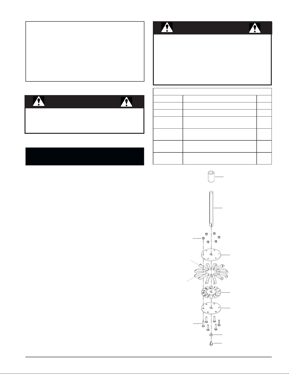
12 BLADE CUTTER UPGRADE KIT, PN 76906-00
PART # DESCRIPTION QTY
15059 BOLT, 3/8 X 1 3/4" CRG 12
15388 NUT, 3/8 NYLOCK 12
76898-12
76899-12
76900-12
76907-00
PLATE, COVER STUMP GRINDER
HEAD
PLATE, SPACER STUMP GRINDER
HEAD
PLATE, DISK STUMP GRINDER
HEAD
INSTRUCTIONS, SG340 CUTTER
UPGRADE
1
2
1
1
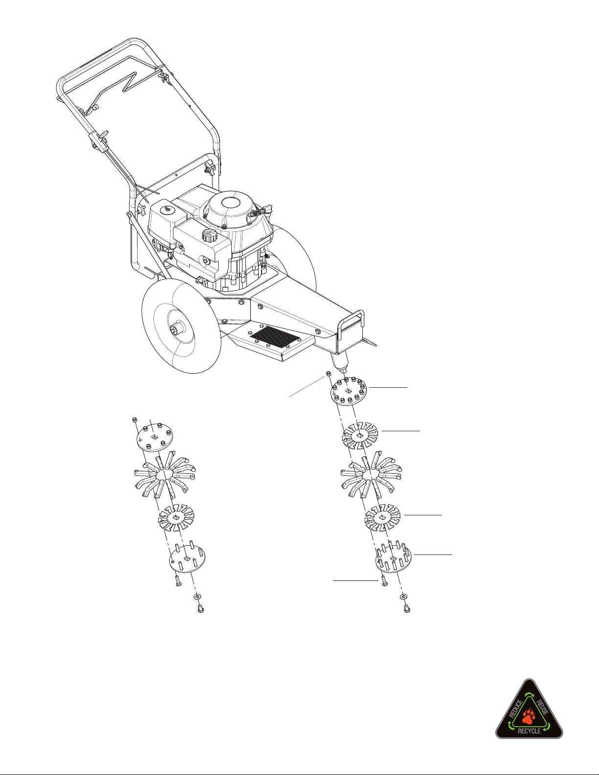
1. Position and secure the machine to best access the
cutter assembly.
2. Loosen and remove the existing 1/2 X 3/4" bolt and
washer from spindle located at the bottom of the cutter
assembly.
3. Remove the plates and blades assembly from the
spindle.
4. Loosen and remove the existing 6 bolts, nuts and
washers in the cutter assembly.
5. Separate the plates, remove the 12 cutting blades and
set blades aside.
6. Discard the three plates
TUBE, SPACER, 1-3/4" X 2.770"
SPINDLE, 12 BLADE RETRO
NUT, 3/8" NYLOCK
PLATE, HEAD DISK
TOOTH, STRAIGHT
TOOTH, CURVED
PLATE, HEAD SPACER
PLATE, HEAD COVER
BOLT, 3/8" X 1-3/4" CRG
INSTRUCTION SHEET
WASHER, 1/2" SAE FLAT
BOLT, 1/2" X 3/4" NF
PN 76907-00
Rev. 092010
Page 2
ASSEMBLING THE 12 BOLT/12 BLADE KIT, UPGRADE CUTTING SYSTEM
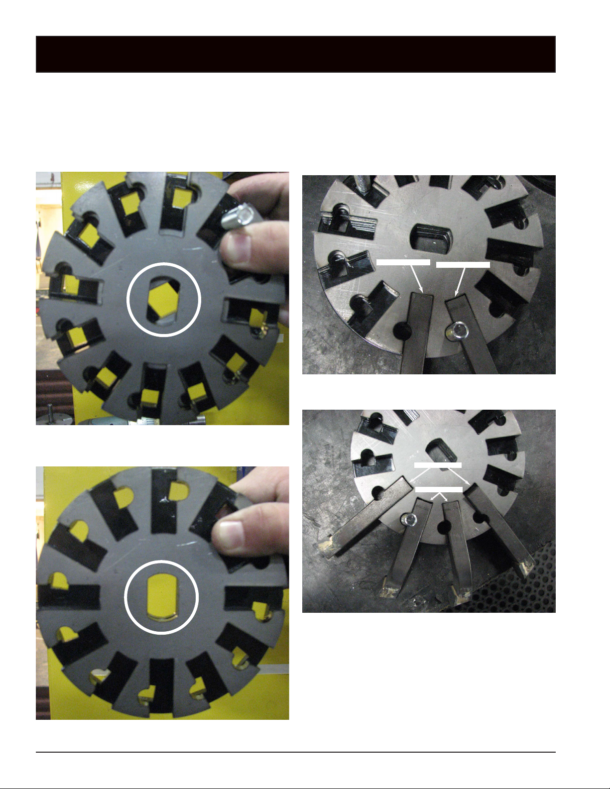
1. Begin by placing the painted bottom plate (76898-12
(with square holes)) on a flat working area.
2. Place the two spacer plates (76899-12) on the bottom
plate and align center spindle hole and 12 bolt holes
of the spacer plates to the spindle hole and bolt hole
of the bottom plate. (See photos below.)
3. Begin placing the cutting blades (removed in step 5 of
the disassembly) into the blade openings of the aligned
space plates. (Placing two of the new 3/8" X 1 3/4"
carriage bolts (15059), up from the bottom, hrough the
hole locations will help keep the plates aligned during
the following steps.)
Straight Blade Inset
Angled Blade Inset
Spacer plates INCORRECTLY
aligned to bottom plate.
Straight Blade Inset
Angled Blade Inset
Spacer plates CORRECTLY
aligned to bottom plate.
INSTRUCTION SHEET
Page 3

NOTE
IT IS IMPORTANT TO NOTE THE SPECIFIC
SEQUENCE AND ORIENTATION THE BLADES
MUST BE IN FOR SUCCESSFUL ASSEMBLY
AND OPERATION OF THE SUTTER SYSTEM.
6. Put all of the remaining bolts into the holes from the
bottom.
7. Place the painted cover plate (76900-12) over and on
to the 12 bolts of the assembly and secure plate into
place using the twelve 3/8" lock nuts (15388).
Top view of spacer plates with blades in place and properly oriented so
the blade tips point in a clockwise direction.
4. There are four straight cutting blades and eight angled
blades.
5. The angled blades are shorter than the straight blades
and are placed next to each other with a straigh blade
placed next. Continue until all 12 blades are in place.
8. Install the cutter assembly on to the spindle, making
sure the angled blades point down. Also make sure the
end of the spindle is flush with the bottom plate and
secure into place using the 1/2 X 3/4" bolt and washer
removed in step 1 of the disassembly. Torque bolt to
70 ft. lbs.
Bottom view of cutter assembly with the
spindle mounted flush to bottom plate.
INSTRUCTION SHEET
Page 4
NUT, 3/8" NYLOCK
BOLT, 3/8" X
1-3/4" CRG
PLATE, HEAD
DISK
PLATE, HEAD
SPACER
PLATE, HEAD
SPACER
PLATE, HEAD
COVER
ECHO BEAR CAT
www.bearcatproducts.com
237 NW 12th Street, West Fargo, ND 58078-0849
Phone: 701.282.5520 • Toll Free: 800.247.7335 • Fax: 701.282.9522
E-mail: service@bearcatproducts.com • sales@bearcatproducts.com
 Loading...