

Page 1

4 inch
MadE WIth pRIdE In thE...
chipper
73413 - 13 hp honda
73413S - 13 hp honda
73420 - 20 hp honda
73420f - 20 hp honda
73420S - 20 hp honda
73454 - pto
owner's manual
73454S - pto
pn: 12127 R011107
Companion to 12128
Page 2

Before You Begin
ManuFaCtuREd By CRaRy InduStRIES
ManuFaCtuREd In u.S.a.
xxxxxx
WESt FaRgo, noRth dakota 58078 u.S.a.
SERIal nuMBER
Dear echo Bear caT cusTomer
thank you for purchasing an ECho Bear Cat product. the ECho Bear Cat line is designed, tested, and manufactured to give years
of dependable performance. To keep your machine operating at peak efciency, it is necessary to adjust it correctly and make regular inspections. the following pages will assist you in the operation and maintenance of your machine. please read and understand
this manual before operating your machine.
If you have any questions or comments about this manual, please call us toll-free at 1-800-247-7335.
If you have any questions or problems with your machine, please call or write your local authorized ECho Bear Cat dealer.
this document is based on information available at the time of its publication. ECho Bear Cat is continually making improvements
and developing new equipment. In doing so, we reserve the right to make changes or add improvements to our product without
obligation for equipment previously sold.
please senD us Your warranTY carD
A warranty card is included in your owner's kit packaged with your machine. Please take the time to ll in the information requested
on the card. When you send your completed card to us, we will register your machine and start your coverage under our limited
warranty.
parTs orDerinG inFormaTion
For service assistance or parts, contact your nearest authorized
ECho Bear Cat dealer or the factory. your nearest authorized
dealer will need to know the serial number of your machine to
provide the most efcient service. See below for information on
how to identify and record the serial number for your machine.
if you need engine service or parts:
For engine service or parts, contact your nearest authorized engine dealer. an authorized engine dealer can handle all parts,
repairs, and warranty service concerning the engine.
serial numBer locaTion
please record the serial number in the space provided and on
the warranty and registration card.
replacemenT parTs
only genuine ECho Bear Cat replacement parts should be
used to repair the machine. Replacement parts manufactured
by others could present safety hazards, even though they may
t on this machine. Replacement parts are available from your
ECho Bear Cat dealer.
Provide the following when ordering parts:
the SERIal nuMBER of your machine.
the paRt nuMBER of the part.
the paRt dESCRIptIon.
the QuantIty needed.
serial numBer
how To conTacT echo Bear caT
addreSS Phone e-mail hourS
237 nW 12th Street
p.o. Box 849
West Fargo, nd 58078
800-247-7335
701-282-5520
Fax: 701-282-9522
© 2006, CRaRy InduStRIES, all RIghtS RESERvEd. pRoduCEd and pRIntEd In thE u.S.a.
opesales@crary.com
service@crary.com
Monday - Friday,
8 am to 5 pm
Central time
Page 3

limiTed WarranTY
this warranty applies to all ag and outdoor power Equipment manufactured by Crary Industries.
Crary Industries warrants to the original owner each new Crary Industries product to be free from defects
in material and workmanship, under normal use and service. the warranty shall extend 1 year from date of
delivery for income producing (commercial) applications and 2 years from date of delivery for non-income
producing (consumer) use of the product. the product is warranted to the original owner as evidenced by a
completed warranty registration on file at Crary Industries. Replacement parts are warranted for (90) days
from date of installation.
The WarranTY regiSTraTion muST be comPleTed and reTurned To crarY induSTrieS
WiThin 10 daYS of deliverY of The ProducT To The original oWner or The WarranTY
Will be void.
In the event of a failure, return the product, at your cost, along with proof of purchase to the selling Crary
Industries dealer. Crary Industries will, at its option, repair or replace any parts found to be defective in material
or workmanship. Warranty on any repairs will not extend beyond the product warranty. Repair or attempted
repair by anyone other than a Crary Industries dealer as well as subsequent failure or damage that may occur
as a result of that work will not be paid under this warranty. Crary Industries does not warrant replacement
components not manufactured or sold by Crary Industries.
this warranty applies only to parts or components that are defective in material or workmanship.
1.
this warranty does not cover normal wear items including but not limited to bearings, belts, pulleys, filters
2.
and chipper knives.
This warranty does not cover normal maintenance, service or adjustments.
3.
this warranty does not cover depreciation or damage due to misuse, negligence, accident or improper
4.
maintenance.
This warranty does not cover damage due to improper setup, installation or adjustment.
5.
this warranty does not cover damage due to unauthorized modifications of the product.
6.
Engines are warranted by the respective engine manufacturer and are not covered by this warranty.
7.
Crary Industries is not liable for any property damage, personal injury or death resulting from the unauthorized
modification or alteration of a Crary product or from the owner’s failure to assemble, install, maintain or operate
the product in accordance with the provisions of the owner’s manual.
Crary Industries is not liable for indirect, incidental or consequential damages or injuries including but not
limited to loss of crops, loss of profits, rental of substitute equipment or other commercial loss.
this warranty gives you specific legal rights. you may have other rights that may vary from area to area.
Crary Industries makes no warranties, representations or promises, expressed or implied as to the performance
of its products other than those set forth in this warranty. neither the dealer nor any other person has any
authority to make any representations, warranties or promises on behalf of Crary Industries or to modify the
terms or limitations of this warranty in any way. Crary Industries, at its discretion, may periodically offer limited,
written enhancements to this warranty.
crarY induSTrieS reServeS The righT To change The deSign and/or SPecificaTionS
of iTS ProducTS aT anY Time WiThouT obligaTion To PreviouS PurchaSerS of iTS
ProducTS.
4 INCH CHIPPER
1
Page 4

Page 5

Table of conTenTS
deScriPTion Page deScriPTion Page
SafeTY .................................................................5
1.1 SaFEty alERt SyMBol ..............................................5
1.2 EMISSIon InFoRMatIon ............................................ 5
1.3 BEFoRE opERatIng ...................................................6
1.4 opERatIon SaFEty .................................................... 6
1.5 pto SaFEty ..................................................................7
1.6 BattERy SaFEty .........................................................7
1.7 MaIntEnanCE/StoRagE SaFEty ............................ 8
1.8 toWIng SaFEty .......................................................... 8
1.9 SaFEty dECal loCatIonS (73413, 73420, 73454) 12
1.10 SaFEty dECal loCatIonS (73413S, 73420S,
73454S) ........................................................................12
1.11 SaFEty dECalS ......................................................... 12
aSSemblY ..........................................................15
2.1 EngInE ModEl aSSEMBly .......................................15
2.1.1 attaCh tRaIlER axlE ................................... 15
2.1.2 attaCh tRaIlER WhEElS ............................. 15
2.1.3 attaCh tRaIlER hItCh .................................15
2.1.4 attaCh ChIppER ChutE ............................... 16
2.1.5 attaCh ExtEnSIon tRay ("S" ModElS) .....16
2.1.6 attaCh BloWER dISChaRgE tuBE ............16
2.1.7 BattERy InStallatIon (73420) ...................17
2.1.8 ChECkIng/addIng MotoR oIl .................... 17
2.1.9 FIllIng thE FuEl tank .................................17
2.2 pto ModEl aSSEMBly ............................................18
2.2.1 attaCh ChIppER ChutE ............................... 18
2.2.2 attaCh ExtEnSIon tRay ("S" ModElS) .....18
2.2.3 attaCh BloWER dISChaRgE tuBE ............18
2.2.4 ConnECt pto ShaFt ....................................19
conTrolS and oPeraTion ...........................20
3.1 EngInE ModEl ContRolS .....................................20
3.1.1 ChIppER ContRolS ......................................20
3.1.2 13 hp honda EngInE ContRolS ............... 21
3.1.3 20 hp honda EngInE ContRolS ............... 21
3.2 pto ModEl ContRolS ............................................ 22
3.3 StaRtIng .................................................................... 23
3.3.1 StaRtIng 13 hp ModElS ..............................23
3.3.2 StaRtIng 20 hp ModElS ..............................23
3.3.3 StaRtIng pto ModElS................................. 23
3.4 StoppIng ...................................................................24
3.4.1 StoppIng EngInE ModElS .........................24
3.4.2 StoppIng pto ModElS ................................ 24
3.5 ChIppIng .....................................................................24
Service & mainTenance ...............................25
4.1 SERvICE & MaIntEnanCE SChEdulE ...................25
4.2 ShaRpEnIng ChIppER BladES ..............................26
4.3 SEttIng BladE ClEaRanCE...................................27
4.4 adJuStIng/REplaCIng dRIvE BElt ...................... 27
4.4.1 EngInE ModEl dRIvE BElt ..........................27
4.4.2 pto ModEl dRIvE BEltS ..............................27
4.5 ClEaRIng pluggEd RotoR ...................................28
4.6 REplaCIng RotoR BEaRIngS ................................28
4.6.1 REplaCIng EngInE ModEl BEaRIngS ......28
4.6.2 REplaCIng pto ModEl BEaRIngS.............28
4.7 gREaSEaBlE BEaRIngS .......................................... 29
4.8 pto luBRICatIon ......................................................29
TroubleShooTing .........................................30
SPecificaTionS ................................................
6.1 ChIppER SpECIFICatIonS .......................................32
6.2 Bolt toRQuE ............................................................. 33
4 INCH CHIPPER
32
3
Page 6

Page 7
1
SafeTY
Section
1.1 SafeTY alerT SYmbol 1.2 emiSSion informaTion
Warning To all california and oTher STaTeS
oPeraTing ouTdoor PoWer eQuiPmenT
under California law and under
the laws of several other states,
you are not permitted to operate
an internal combustion engine
using hydrocarbon fuels on any
forest covered, brush covered
or grass covered land or on land
covered with grain, hay or other ammable agricultural
the owner/operator's manual uses this symbol to alert
you of potential hazards. Whenever you see this symbol,
read and obey the safety message that follows it. Failure
to obey the safety message could result in personal injury,
death or property damage.
cauTion
Indicates a potentially hazardous situation that, if not
avoided, may result in minor or moderate injury.
Warning
Indicates a potentially hazardous situation that, if not
avoided, could result in death or serious injury.
danger
Indicates an imminently hazardous situation that, if not
avoided, will result in death or serious injury.
crops, without an engine spark arrester in continuous effective working order.
the engine on your power equipment, like most outdoor
power equipment, is an internal combustion engine that
burns gasoline (a hydrocarbon fuel). therefore, your
power equipment must be equipped with a spark arrester
mufer in continuous effective working order. The spark
arrester must be attached to the engine exhaust system
in such a manner that ames or heat from the system will
not ignite ammable material.
Failure of the owner/operator of the equipment to comply
with this regulation is a misdemeanor under California law
and may also be a violation of other state and/or federal
regulations, laws, ordinances, or codes. Contact your lo-
cal re marshal or forest service for specic information
about which regulations apply in your area.
The standard mufer installed on the 13 HP Honda
engine is equipped with a spark arrester. The mufer
installed on the 20 hP honda engine is noT equipped
with a spark arrester. one must be added to the 20 hP
engine mufer before using this machine in an area
where a spark arrester is required by law. Contact the
local authorities if these laws apply to you. See your authorized engine dealer for spark arrester options.
4 INCH CHIPPER
5
Page 8
SAFETY
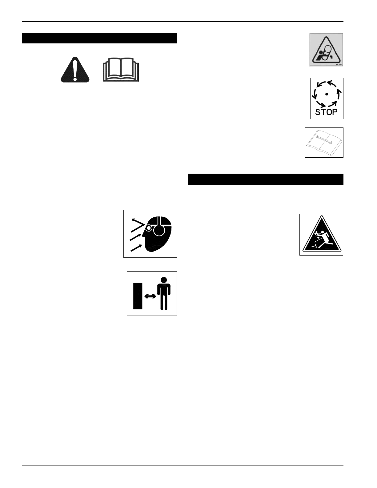
1.3 before oPeraTing
Read and understand this owner/operators manual.
1.
Be completely familiar with the controls and the proper
use of this equipment.
Familiarize yourself with all of the safety and operating
2.
decals on this equipment and on any of its attachments
or accessories.
keep safety decals clean and legible. Replace missing
3.
or illegible safety decals.
obtain and wear safety glasses and use hearing pro-
4.
tection at all times when operating this machine.
avoid wearing loose fitted clothing. never operate this
5.
machine wearing clothing with drawstrings that could
wrap around or get caught in the machine.
do not operate this machine
6.
if you are under the influence
of alcohol, medications, or
substances that can affect your
vision, balance or judgement.
do not operate if tired or ill. you
must be in good health to operate this machine safely.
do not operate this equipment in
7.
the vicinity of bystanders. keep
the area of operation clear of
all persons, particularly small
children. It is recommended that
bystanders keep at least 50 feet
(15 meters) away from the area
of operation.
do not allow children to operate this equipment.
8.
use only in daylight or good artificial light.
9.
do not run this equipment in an enclosed area. Engine
10.
exhaust contains carbon monoxide gas, a deadly poison that is odorless, colorless and tasteless. do not
operate this equipment in or near buildings, windows
or air conditioners.
always use an approved fuel container. do not remove
11.
gas cap or add fuel when engine is running. add fuel
to a cool engine only.
do not fill fuel tank indoors. keep open flames, sparks,
12.
smoking materials and other sources of combustion
away from fuel.
do not operate machine without shields in place. Fail-
13.
ure to do so may cause serious injury or death.
keep all guards, deflectors, and
14.
shields in good working condition.
Before inspecting or servicing any part
15.
of this machine, shut off power source,
disconnect spark plug wire from spark
plug and make sure all moving parts
have come to a complete stop.
Check that all screws, nuts, bolts, and
16.
other fasteners are secured, tightened
and in proper working condition before
starting the machine and once every
8 hours of operation.
do not transport or move machine
17.
while the machine is operating or
running.
1.4 oPeraTion SafeTY
always stand clear of discharge area when operating
1.
this machine. keep face and body away from feed
and discharge openings.
keep hands and feet out of feed and
2.
discharge openings while machine is
operating to avoid serious personal
injury. Stop and allow machine to
come to a complete stop before
clearing obstructions.
Set up your work site so you are not endangering traffic
3.
and the public. take great care to provide adequate
warnings.
do not climb on machine when operating. keep proper
4.
balance and footing at all times.
Check cutting chamber to verify it is empty before
5.
starting the machine.
the rotor will continue to rotate when belt is disen-
6.
gaged.
do not insert branches larger than 4 inches in diameter
7.
into chipper or machine damage may occur.
When feeding material into machine, do not allow
8.
metal, rocks, bottles, cans or any other foreign material
to be fed into the machine.
Ensure debris does not blow into traffic, parked cars,
9.
or pedestrians.
keep the machine clear of debris and other accumula-
10.
tions.
do not allow processed material to build up in the
11.
discharge area. this may prevent proper discharge
and can result in kickback of material through the feed
opening.
6
4 INCH CHIPPER
Page 9

danger / PoiSon
ShIEld EyES
ExploSIvE gaSES
Can CauSE
BlIndnESS oR
InJuRy
no
• SpaRkS
• FlaMES
• SMokIng
SulFuRIC
aCId
Can CauSE
BlIndnESS oR
SEvERE BuRnS
FluSh EyES
IMMEdIatEly
WIth WatER
gEt
MEdICal
hElp
FaSt
kEEp out oF thE REaCh oF ChIldREn. do not tIp. kEEp vEnt CapS tIght and lEvEl.
1.4 oPeraTion SafeTY (conT.)
Shut off machine immediately if the machine becomes
12.
clogged, the cutting mechanism strikes any foreign
object, or the machine starts vibrating or making an
unusual noise. Shut off power source, disconnect
spark plug wire from spark plug and make sure all
moving parts have come to a complete stop. after
machine stops:
Inspect for damage.
a.
Replace or repair any damaged
B.
parts.
Check for and tighten any loose
C.
parts.
on electric start models, disconnect spark plugs before
13.
doing any inspection or service.
Check blade bolts for proper torque after every 8 hours
14.
of operation. Check blades and rotate or resharpen
daily or as required to keep blades sharp. Failure to do
so may cause poor performance, damage or personal
injury and will void the machine warranty.
1.5 PTo SafeTY
Read and follow instructions on pto safety decals.
1.
Stay alert and pay attention when pto is operating.
2.
keep bystanders, especially children, away from pto
3.
driveline.
Check the driveline to ensure it is attached securely
4.
to the power supply.
keep guards and shields in place at all times while
5.
operating. disengage pto, shut off power source,
disconnect spark plug wire from spark plug and make
sure all moving parts have come to a complete stop
before removing guards
or shields.
Clothing worn by opera-
6.
tor must be fairly tight.
never wear loose fitted
jackets, shirts, or pants
when working around
the pto. tie long hair
back or put under a
cap.
SAFETY
Before inspecting or ser-
9.
vicing the pto drive area,
disengage the driveline,
shut off power source,
disconnect spark plug
wire from spark plug and
make sure all moving
parts have come to a
complete stop.
keep hands, feet, and
10.
clothing away from all pto drive parts.
Do not clean, lubricate or adjust the PTO shaft when
11.
it is running.
1.6 baTTerY SafeTY
Improper use and care of the battery on electric start models can result in serious personal injury or property damage. always observe the following safety precautions.
poison/danger - Causes Severe Burns. the battery
1.
contains sulfuric acid. avoid contact with skin, eyes
or clothing. keep out of reach of children.
antIdotE-External Contact: Flush immediately
with lots of water.
antIdotE-Internal: drink large quantities of
water or milk. Follow with milk of magnesia,
beaten egg or vegetable oil. Call a physician immediately.
antIdotE-Eye Contact: Flush with water for 15
minutes. get prompt medical attention.
the battery produces explosive gases. keep sparks,
3.
flame or cigarettes away. ventilate area when charging battery. always wear safety goggles when working
near battery.
the battery contains toxic materials. do not damage
4.
battery case. If case is broken or damaged, avoid
contact with battery contents.
neutralize acid spills with a baking soda and water
5.
solution. properly dispose of a damaged or wornout battery. Check with local authorities for proper
disposal methods.
do not short circuit battery. Severe fumes and fire
6.
can result.
Before working with electrical wires or components,
7.
disconnect battery ground (negative) cable first. disconnect positive cable second. Reverse this order
when reconnecting battery cables.
keep hydraulic hoses, electric cords, chains and other
7.
items from contacting the driveline.
do not exceed the recommended 540 RpM pto op-
8.
erating speed.
4 INCH CHIPPER
7
Page 10

SAFETY
1.7 mainTenance/STorage SafeTY
Before inspecting, servicing, storing, or changing an
1.
accessory, shut off power source, disconnect spark
plug wire from spark plug and make sure all moving
parts have come to a complete stop.
Replace any missing or unreadable safety decals. Re-
2.
fer to the parts manual for part numbers when ordering
safety decals from your chipper dealer.
allow machine to cool before storing in an enclosure.
3.
Store the machine out of reach of children and where
4.
fuel vapors will not reach an open flame or spark.
never store this machine with fuel in the fuel tank
5.
inside a building where fumes may be ignited by an
open flame or spark. Ignition sources can be hot water
and space heaters, furnaces, clothes dryers, stoves,
electric motors, etc.
drain the fuel and dispose of it in a safe manner for
6.
storage periods of three months or more.
1.8 ToWing SafeTY
towing laws may vary in different countries/regions/
1.
states. It is recommended that you contact your local
motor vehicle department for any special rules that
pertain to towing and to know the rules of any country/region/state you may travel through.
Connect hitch safety chains. tighten and secure trailer
2.
hitch bolts. do not attempt to tow the trailer if vehicle
is not equipped with the proper size hitch ball.
Check wheel lug bolts periodically to ensure they are
3.
tight and secure.
Place the jack stand on the trailer in the UP position
4.
to clear the ground while towing. Place the jack stand
on a level surface and secure it in the doWn position
before using.
never allow passengers to ride on the chipper.
5.
If applicable, shut off fuel supply when towing.
6.
8
4 INCH CHIPPER
Page 11

ThiS Page inTenTionallY lefT blanK
4 INCH CHIPPER
9
Page 12
SAFETY
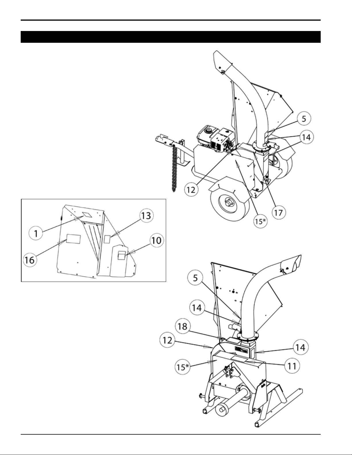
1.9 SafeTY decal locaTionS (73413, 73420, 73454)
See pages 12-13 for numbered decal pictures and descriptions.
* dECal 15, #17423, IS loCatEd on thE dRIvE
BElt ShIEld undERnEath thE BElt guaRd.
10
4 INCH CHIPPER
Page 13

1.10 SafeTY decal locaTionS (73413S, 73420S, 73454S)
See pages 12-13 for numbered decal pictures and descriptions.
SAFETY
* dECal 6, #12174, IS loCatEd on thE dRIvE
BElt ShIEld undERnEath thE BElt guaRd.
4 INCH CHIPPER
11
Page 14

SAFETY
1.11 SafeTY decalS
Safety and instruction decals are located on the chipper frame and engine. Replace any decal that is damaged or unreadable.
Pn 12173
5
do not opERatE thIS EQuIpMEnt In thE vICInIty oF By-
Pn 12010
1
Pn 12168
2
kEEp handS, FEEt and Body
aWay FRoM dRIvEShaFt
WhIlE MaChInE IS opERat
Ing to avoId EntanglEMEnt. opERatE MaChInE at
540 RpM.
-
StandERS. do not alloW
ChIldREn to opERatE thIS
EQuIpMEnt. alWayS Stand
ClEaR oF dISChaRgE aREa
WhEn opERatIng thIS MaChInE. kEEp FaCE and Body
aWay FRoM dISChaRgE aREaS.
Pn 12174
6
do not opERatE MaChInE
WIthout ShIEldS In plaCE.
FaIluRE to do So May CauSE
SERIouS InJuRy oR dEath.
Pn 12169
3
kEEp handS and FEEt
out oF InlEt and
dISChaRgE opEnIngS WhIlE
MaChInE IS opERatIng to
avoId SERIouS pERSonal
InJuRy. alloW MaChInE to
CoME to a CoMplEtE Stop
BEFoRE ClEaRIng oBStRuCtIonS.
Pn 12172
4
REad and undERStand thIS
oWnER/opERatoRS Manual.
BE CoMplEtEly FaMIlIaR WIth
thE ContRolS and thE pRopER uSE oF thIS EQuIpMEnt.
oBtaIn and WEaR SaFEty
glaSSES and uSE hEaRIng
pRotECtIon at all tIMES
WhEn opERatIng thIS Ma
ChInE.
BEFoRE InSpECtIng oR SER
vICIng any paRt oF thIS
MaChInE, Shut oFF poWER
SouRCE, dISConnECt SpaRk
plug WIRE FRoM SpaRk plug
and MakE SuRE all MovIng
paRtS havE CoME to a CoMplEtE Stop.
Pn 12175
7
kEEp handS and FEEt out
oF InlEt and dISChaRgE
opEnIngS WhIlE MaChInE IS
opERatIng to avoId SERIouS pERSonal InJuRy. alloW MaChInE to CoME to
a CoMplEtE Stop BEFoRE
ClEaRIng oBStRuCtIonS.
Pn 12183
8
pRESS ClutCh pEdal
doWn WIth Foot to
dISEngagE BElt WhIlE
StaRtIng EngInE. SloWly
RElEaSE Foot to EngagE
ChIppER BElt aFtER ChIp-
-
-
pER IS RunnIng.
12
4 INCH CHIPPER
Page 15

1.11 SafeTY decalS (conT.)
Pn 12250
9
ChECk BladE BoltS FoR
pRopER toRQuE aFtER EvERy 8 houRS oF opERatIon.
ChECk BladES and RotatE
oR REShaRpEn daIly oR aS
REQuIREd to kEEp BladES
ShaRp. REFER to oWnERS
Manual FoR InStRuCtIonS.
FaIluRE to do So May CauSE
pooR pERFoRManCE, daMagE
oR pERSonal InJuRy and WIll
voId thE MaChInE WaRRanty.
13
SAFETY
Pn 16551
10
REad and undERStand
thIS oWnER/opERatoRS
Manual. BE CoMplEtEly
FaMIlIaR WIth thE
ContRolS and thE
pRopER uSE oF thIS
EQuIpMEnt.
11
Pn 13711-00
Pn 16033
14
15
16
Pn 16558
Pn 17423
Pn 17837
12
Pn 16085
4 INCH CHIPPER
13
Page 16

SAFETY
1.9 SafeTY decalS (conT.)
17
Pn 17846
18
Pn 18443-00
14
4 INCH CHIPPER
Page 17

2
aSSemblY
Section
2.1 engine model aSSemblY
noTe
axle, wheel and hitch assemblies for the 73420F model
are supplied by the distributor and may vary from the
illustrations shown in this manual.
2.1.1 aTTach Trailer axle
Remove the chipper from the shipping crate and place
1.
on a level surface.
Raise the trailer several inches from the ground with a
2.
hoist or jack. Ensure the chipper is well supported.
position the fenders over the axle and secure with
3.
eight 3/8" x 1-1/4" bolts and nylock nuts (Figure 2.1).
tighten to 35 ft-lbs.
align the axle with the mounting brackets on the sides
4.
of the chipper trailer. Secure with four 1/2" x 1-1/4"
bolts, washers and centerlock nuts. tighten to 75
ft-lbs.
2.1.2 aTTach Trailer WheelS
hold one wheel to a hub and align the wheel lug holes
1.
with the hub lug holes.
thread the lug bolts into the holes and tighten to 75
2.
ft-lbs. Follow a star pattern when tightening lug bolts.
Repeat for the remaining wheel.
3.
2.1.3 aTTach Trailer hiTch
attach the adjustable hitch to the hitch channel on the
1.
trailer bottom with three 3/8" x 3-1/2" bolts, washers
and nylock nuts (included in owner's kit).
attach the two safety chains to the hitch pole with a
2.
3/8" x 3-1/2" hex bolt, two washers and a nylock nut
as shown in Figure 2.2.
Slide the 2 inch (50 mm) ball coupler onto the hitch
3.
pole. Bolt the coupler to the pole with two 1/2" x 3" hex
bolts and centerlock nuts.
Secure the jack stand to the hitch pole with a snap
4.
pin.
tighten 1/2" bolts to 75 ft-lbs. and 3/8" bolts to
5.
35 ft-lbs.
Figure 2.1, Attaching the trailer axle
Figure 2.2, Trailer hitch assembly
4 INCH CHIPPER
15
Page 18

ASSEMBLY
2.1 engine model aSSemblY (conT.)
2.1.4 aTTach chiPPer chuTe
use a support or hoist to hold the chipper chute in
1.
place on the chipper frame.
Mount the chute to the chipper housing using six 3/8"
2.
x 1" carriage bolts and nylock nuts.
Warning
do not operate this unit without the chipper chute
correctly installed. Rotating cutting blades can cause
serious personal injury.
2.1.5 aTTach exTenSion TraY ("S" modelS)
attach the extension hinge to the chipper chute with
1.
three 3/8" x 1-1/4" bolts, washers and nylock nuts.
Slide the chute extension tray over the chipper chute.
2.
position the lip of the extension tray behind the lip on
the chipper chute (Figure 2.3). align the three bolt
holes in the chute extension tray with the bolt holes
in the hinge.
Insert three 3/8" x 1" carriage bolts through the tray
3.
and the extension hinge. Secure the bolts with washers and nuts.
Connect the gas spring to the side of the chipper chute
4.
and extension tray with ball studs and 5/16" nylock nuts
as shown in Figure 2.3.
2.1.6 aTTach bloWer diScharge Tube
Slide the blower tube discharge clamp underneath the
1.
mounting flange on the chipper frame.
Install the second half of the spacer and clamp (in-
2.
cluded in owner's kit) to the tube and flange with 3/8"
x 1-1/4" bolts and nylock nuts (Figure 2.4). Rotate the
tube 360 degrees to make sure it is mounted correctly.
lock it in place with the lock lever.
Figure 2.4, Chipper discharge assembly
16
Figure 2.3, Attaching the extension tray ("S" models only)
4 INCH CHIPPER
Page 19

2.1 engine model aSSemblY (conT.)
ASSEMBLY
2.1.7 baTTerY inSTallaTion (73420)
Check battery condition. Charge if needed.
1.
use the battery cover, battery angle bracket, two 5/16"
2.
l-type battery bolts, nylock nuts and washers from the
owner's kit to install the battery between the chipper
frame and engine mount (Figure 2.5).
place the cover over the battery (non-terminal side)
3.
and set on trailer with the cover positioned between
the chipper frame and the battery.
place the angle bracket over the opposite side of the
4.
battery (terminal side).
Run the two battery bolts through the bolt holes in the
5.
bottom of the trailer frame and angle bracket. Secure
with washers and nuts on the tops of the bolts.
Connect the positive battery cable to the positive bat-
6.
tery terminal and the negative cable to the negative
terminal.
2.1.9 filling The fuel TanK
For best results use only clean, fresh, unleaded gasoline
with a pump octane rating of 86 or higher or a research
octane rating of 91 or higher.
purchase gasoline in small quantities and store in
clean, approved containers. do not MIx oIl WIth
gaSolInE.
ethanol
gasohol (up to 10% ethyl alcohol, 90% unleaded gasoline
by volume) is an approved fuel for honda engines. other
gasoline/alcohol blends are not approved.
mTbe
Methyl tertiary Butyl Ether (MtBE) and unleaded gasoline
blends (up to a maximum of 15% MtBE by volume) are
an approved fuel for honda engines. other gasoline/ether
blends are not approved.
methanol
Methanol (up to a maximum of 5% volume) is approved for
honda engines. Methanol blends must contain cosolvents
and corrosion inhibitors to protect the fuel system. gasoline
containing more than 5% methanol may cause engine
problems.
Figure 2.5, Installing the battery
2.1.8 checKing/ adding moTor oil
Check the oil level. If needed, fill the engine with the
type and amount of oil specified in the engine owner's
manual.
To add gasoline
Stop engine, wait for all parts to stop moving and dis-
1.
connect spark plug wire. Remove key from key switch.
allow the engine and muffler to cool for at least three
minutes.
Clean area around fuel fill cap and remove cap.
2.
using a clean funnel, fill fuel tank to 1/2" below bottom
3.
of filler neck to provide space for any fuel expansion.
Install fuel fill cap securely and wipe up any spilled
gasoline.
Warning
Gasoline is highly ammable and its vapors are explo-
sive. To prevent personal injury or property damage:
Store gasoline only in approved containers, in well
ventilated, unoccupied buildings, away from sparks
or flames. do not fill the fuel tank while the engine is
hot or running. Spilled fuel could ignite if it comes in
contact with hot parts or sparks from ignition. do not
start the engine near spilled fuel. never use gasoline
as a cleaning agent.
4 INCH CHIPPER
17
Page 20

ASSEMBLY
2.2 PTo model aSSemblY
2.2.1 aTTach chiPPer chuTe
use a support or hoist to hold the chipper chute in
1.
place on the chipper frame
Mount the chute to the chipper housing using four 3/8"
2.
x 1-1/2" bolts and locknuts.
Warning
do not operate this unit without the chipper chute
correctly installed. Rotating cutting blades can cause
serious personal injury.
2.2.2 aTTach exTenSion TraY ("S" modelS)
attach the extension hinge to the chipper chute with
1.
three 3/8" x 1-1/4" bolts, washers and nylock nuts.
Slide the chute extension tray over the chipper chute.
2.
position the lip of the extension tray behind the lip
on the chipper chute (Figure 2.6). align the four bolt
holes in the chute extension tray with the bolt holes
in the hinge.
Insert four 3/8" x 1" carriage bolts through the tray and
3.
the extension hinge. Secure the bolts with washers
and nuts.
Connect the gas spring to the side of the chipper chute
4.
and extension tray with ball studs and 5/16" nylock nuts
as shown in Figure 2.6.
2.2.3 aTTach bloWer diScharge Tube
Slide the blower tube discharge clamp underneath the
1.
mounting flange on the chipper frame.
Install the second half of the spacer and clamp (in-
2.
cluded in owner's kit) to the tube and flange with 3/8"
x 1-1/4" bolts and nylock nuts (Figure 2.7). Rotate the
tube 360 degrees to make sure it is mounted correctly.
lock it in place with the lock lever.
Figure 2.7, Chipper discharge assembly
18
Figure 2.6, Attaching the extension tray ("S" models only)
4 INCH CHIPPER
Page 21

2.2 PTo model aSSemblY (conT.)
2.2.4 connecT PTo ShafT
attach chipper to tractor with 3 point hitch. Adjust the
1.
machine up and down to find the shortest distance
between the chipper rotor shaft and tractor pto. Stop
the machine in the shortest position.
pull the driveline into two pieces. Connect one end to
2.
the tractor pto and the other end to the chipper rotor
shaft. line up the two halves parallel to each other.
If the shaft of one half extends past the end shield of
the other half as seen in Figure 2.8, you will need to
shorten the driveline. If your driveline is not too long,
skip to step 7.
Measure the distance from the end of the driveline tube
3.
to the bottom of the end shield of the other driveline half
(dimension “a” in Figure 2.8). Measure and mark the
driveline tube 1-9/16” inward from dimension “a.”
ASSEMBLY
Cut the shield tube in the marked position.
4.
5.
using the cut piece of shield tube as your measure
ment, place the cut piece against the end of the shaft.
Mark and cut the shaft.
Repeat step 5 for the other half of the driveline, file both
6.
shaft ends, and slide the two halves back together.
Connect the driveline to the chipper rotor shaft us-
7.
ing the 1/4" key and two set screws contained in the
owner’s kit.
Connect the opposite end of the pto shaft to the
8.
tractor.
-
Figure 2.8, Shortening the driveline
4 INCH CHIPPER
19
Page 22

3
conTrolS and oPeraTion
Section
3.1 engine model conTrolS
3.1.1 chiPPer conTrolS
Trailer hitch: always use 2 inch (50 mm) ball and
1.
safety chains.
Jack stand: always have in up position and clear from
2.
ground when moving. When in use, place in doWn
position on a level surface.
belt guard: never remove guards when in use.
3.
rotor access cover: Remove to expose chipper
4.
blades.
discharge tube: Chipped materials exit through the
5.
rotatable discharge chute.
chipper chute: Feed materials to be chipped through
6.
the chipper chute.
rotor shaft bearing cover: Covers rotor shaft and
7.
front bearing.
adjustable chipping anvil: Adjust to change the size
8.
of chips.
belt engagement pedal: When the pedal is de-
9.
pressed, the drive belt is disengaged. When the pedal
is released, the drive belt is engaged. depress pedal
to start engine.
cauTion
Wear safety glasses at all times when operating the
machine. Do not wear loose tting clothing. The operator should always wear heavy boots, gloves, pants
and shirt. use common sense and practice safety to
protect yourself from branches, sharp objects and
other harmful objects.
noTe
the heavy rotor will continue to turn for some time after
the engine or tractor has been shut off. you can tell
that the rotor has stopped when no noise or machine
vibration is present. Inserting a branch into the chipper
chute to contact the blades will slow the rotor and
shorten stopping time.
20
4 INCH CHIPPER
Figure 3.1, Engine model controls
Page 23

3.1 engine model conTrolS (conT.)
CONTROLS AND OPERATION
noTe
For more detailed engine information, see the engine
owners manual provided with the chipper.
3.1.2 13 hP honda engine conTrolS
engine choke: use when starting a cold engine. push
1.
lever to on position when starting. push to oFF position when engine is running. Full choke may not be
necessary when starting a warm engine. In this case,
partial or no choke may work best.
fuel cut-off switch: push lever to the on position to
2.
start and run engine.
engine throttle: Changes engine speed. push lever
3.
all the way to the on position for full throttle operation.
push the opposite way for engine idle. push all the way
to the oFF position to shut engine off. Refer to engine
manual for further engine operating instructions.
Starter cord: to start, pull the cord until light resistance
4.
is felt and then pull briskly.
engine switch: turn to on position to start and run
5.
engine. to stop, turn to oFF position.
fuel tank: use unleaded gasoline with a pump octane
6.
rating of 86 or higher or a research octane rating of
91 or higher. do not mix with oil. 10 percent ethanol,
15 percent MtBE, or 5 percent methanol blends are
acceptable.
3.1.3 20 hP honda engine conTrolS
engine throttle: Changes engine speed. turn knob
1.
clockwise for full throttle operation. turn knob counterclockwise for engine idle. turn knob fully counterclockwise to shut engine off. Refer to engine manual
for further engine operating instructions.
engine choke: use when starting a cold engine. pull
2.
to on position when starting. push lever to oFF position when engine is running.
Key switch: Release switch from StaRt position as
3.
soon as engine is running. do not crank starter for more
than ten seconds or damage could result.
fuel tank: use unleaded gasoline with a pump octane
4.
rating of 86 or higher or a research octane rating of
91 or higher. do not mix with oil. 10 percent ethanol,
15 percent MtBE, or 5 percent methanol blends are
acceptable.
fuel line: Carries gasoline from fuel tank to engine.
5.
3.2, 13 HP Honda controls
4 INCH CHIPPER
3.3, 20 HP Honda controls
21
Page 24

CONTROLS AND OPERATION
3.2 PTo model conTrolS
Three point hitch connection: Mounts chipper to
1.
tractor three point hitch.
2.
PTo shaft: Connects chipper to tractor pto shaft.
avoid driveline angles over 20 degrees on pto shaft
when unit is in use. notE: Minimum and maximum
telescoping on the pto shaft is 18.11" to 24.49". this
will leave a 6.43" overlap. See Section 2.4 for instructions on checking shaft length.
belt guard: never remove shield while machine is
3.
running.
chipper chute: Feed materials to be chipped through
4.
the chipper chute.
5.
leg stands: never move machine unless the 3 point
is lifted and legs clear the ground.
rotor access cover
6.
blades.
7.
discharge tube
rotatable discharge chute.
adjustable chipping anvil
8.
chips.
rotor shaft bearing cover: Covers rotor shaft and
9.
bearing.
: Remove to expose chipper
: Chipped materials exit through the
: Changes the size of the
cauTion
Wear safety glasses at all times when operating the
machine. Do not wear loose tting clothing. The operator should always wear heavy boots, gloves, pants
and shirt. use common sense and practice safety to
protect yourself from branches, sharp objects and
other harmful objects.
noTe
the heavy rotor will continue to turn for some time after
the engine or tractor has been shut off. you can tell
that the rotor has stopped when no noise or machine
vibration is present. Inserting a branch into the chipper
chute to contact the blades will slow the rotor and
shorten stopping time.
22
Figure 3.4, PTO model controls
4 INCH CHIPPER
Page 25

3.3 STarTing
Warning
Move machine to a clear, level area outdoors before
starting. do not operate machine on a paved, concrete,
or gravel surface. do not operate in the vicinity of
bystanders. Make sure cutting chamber is empty before
starting.
3.3.1 STarTing 13 hP modelS
Before starting, check engine oil level and fill fuel tank
1.
with fresh, clean gasoline use unleaded gasoline with
a pump octane rating of 86 or higher or a research
octane rating of 91 or higher.
Warning
handle gasoline with care. It is highly flammable. always
use an approved container and fill tank outdoors. never
add fuel to a running or hot engine.
CONTROLS AND OPERATION
2.
place the throttle control midway between slow and
fast positions. Move the choke lever to the on position.
notE: When restarting a warm engine after a recent
shut down, it may not be necessary to use a full choke.
If the engine fails to start, move the lever to opEn or
partial choke.
3.
depress belt engagement pedal, which will enable
engine to start. See operation/start-up decal by belt
engagement pedal on machine before starting.
turn the key to the StaRt position. Release the key
4.
as soon as the engine starts. do not crank engine for
more than 10 seconds.
Move choke lever to opEn position.
5.
once engine is running and no choke is needed,
6.
slowly let belt engagement pedal up. this will let the
rotor turn.
If engine kills when engaging the belt, either adjust
7.
choke or increase engine RpM.
3.3.3 STarTing PTo modelS
turn the engine switch to the on position. Make sure
2.
fuel cut-off switch is at the on position.
place the throttle control midway between slow and
3.
fast positions. Move the choke lever to the on posi
tion. notE: When restarting a warm engine after a
recent shut down, it may not be necessary to use a
full choke. If the engine fails to start, move the lever
to Run or partial choke.
4.
depress belt engagement pedal, which will enable
engine to start. See operation/start-up decal by belt
engagement pedal on machine before starting.
pull the starter cord until light resistance is felt and
5.
then pull briskly.
as the engine warms, gradually move the choke lever
6.
to the opEn position.
once engine is running and no choke is needed, slowly
7.
let belt engagement pedal up. this will engage drive
belt, and the rotor will turn.
If engine kills when engaging belt, either adjust choke
8.
or increase engine RpM.
3.3.2 STarTing 20 hP modelS
place tractor transmission in neutral and set parking
1.
brake.
Connect 3 point mounts between the chipper and the
2.
-
tractor. Secure connections with snap pins. Adjust 3
point top link so chipper sits level.
imPorTanT
this chipper is designed to be used with tractor pto's
rated at 15 to 40 horsepower. using this chipper with
pto's above 40 horsepower may cause belt and machine damage in overload conditions
Connect pto shaft to tractor. Make sure you are using
3.
the correct RpM machine.
Start tractor engine and engage pto drive (refer to
4.
tractor owners manual). Increase speed to rated RpM
position.
Warning
do not inspect or work on pto drive area without first
disengaging pto and shutting off tractor.
Before starting, check engine oil level and fill fuel tank
1.
with fresh, clean gasoline use unleaded gasoline with
a pump octane rating of 86 or higher or a research
octane rating of 91 or higher.
4 INCH CHIPPER
23
Page 26

CONTROLS AND OPERATION
3.4 SToPPing
noTe
the heavy rotor will continue to turn for some time after
the engine or tractor has been shut off. you can tell
that the rotor has stopped when no noise or machine
vibration is present. Inserting a branch into the chipper
chute to contact the blades will slow the rotor and
shorten stopping time.
3.4.1 SToPPing engine modelS
Move throttle to slowest position.
1.
depress belt engagement pedal.
2.
turn engine switch to oFF position.
3.
Slowly release the belt engagement pedal to help stop
4.
the rotor.
allow machine to come to a complete stop.
5.
3.4.2 SToPPing PTo modelS
Move tractor throttle to slowest position.
1.
disengage pto lever and shut off tractor engine.
2.
allow machine to come to a complete stop.
3.
3.5 chiPPing
cauTion
obtain and wear safety glasses at all times when
operating the machine. do not wear loose fitting clothing.
the operator should always wear heavy boots, gloves,
pants and shirt. use common sense and practice safety
to protect yourself from branches, sharp objects, and
other harmful objects.
2. Select limbs that are up to 4 inches in diameter. trim
side branches that cannot be bent enough to feed into
the chipper chute. Small diameter branches can be
held together in a bundle and fed in simultaneously.
3. place limb, butt end first, into the chipper chute until it
contacts the chipper blades. the actual feed rate of the
limb into the chipper depends on the type of material
fed and the sharpness of the cutting blades.
4. Never lean over the chute to push objects into the cutting device. use a push stick or brush paddle.
5. never use shovels or forks to push brush. they can
go through the chipper, are expensive to replace, and
cause major damage. In addition, metal pieces can be
shot back like shrapnel to injure or kill the operator or
bystanders.
6. Feed brush from the side of the chute, rather than
from the front. then, step back to avoid being hit by
the brush moving into the chipper.
7. never push brush into the feed chute with your feet.
8. Stop the material feeding and allow the engine to recover if the engine slows to where it may stall.
9. If the chipper jams, remove the branch and rotate it
before reinserting it into the chute. alternately insert
and retract the limb or insert continuously at a rate that
will not kill the engine.
10. Chipping dead, dry material will create heat and dull the
chipping blades quickly. alternate greener material with
dry material to lubricate the chipping blades for longer
life and better performance. When the chipping blades
become dull, they will require sharpening. Refer to the
Service and Maintenance section for more information
on sharpening blades.
Warning
do not leave machine unattended. do not inspect, or
service the machine unless the engine is stopped and
the spark plug is disconnected from its wire.
the chipper is designed to chip a variety of materials into
a more readily decomposing or handled condition. the
following guidelines can be used to help you get started:
Warning
please read and follow all safety instructions in this
manual. Failure to operate the chipper in accordance
with the safety instructions maY reSulT in PerSonal
inJurY!
1. Be sure the unit is at full operating speed before you
start to chip material.
24
4 INCH CHIPPER
Page 27

4
Section
Service & mainTenance
4.1 mainTenance Schedule
the items in the service and maintenance schedule are
to be checked, and if necessary, corrective action taken.
this schedule is designed for units operating under normal conditions. If the unit is operating in adverse or se-
To prevent personal injury or property damage, shut
off power source, disconnect spark plugs, and make
sure all moving parts have come to a complete stop
before servicing, adjusting or repairing.
Warning
vere usage conditions, it may be necessary for the items
to be checked and serviced more frequently. See the engine owners manual for further engine maintenance and
troubleshooting problems.
freQuencY
refer To
comPonenT
aIR ClEanER ChECk and ClEan (1)
aIR IntakE ClEan (1)
EngInE oIl ChangE (1)
FuEl FIltER REplaCE
SpaRk plug ChECk CondItIon/gap
EngInE oIl ChECk
FuEl tank FIll
ChIppER anvIl
ChIppER BladES
all IntERnal and
ExtERnal nutS and
BoltS
BElt CondItIon ChECk
BElt tEnSIon ChECk
gREaSE ZERkS luBE
EntIRE MaChInE ClEan
WhEEl BEaRIngS ChECk and REpaCk
pto CRoSS JouRnalS luBE
pto InnER tuBES luBE
pto ShIEld REtaInIng
BEaRIng
(1) pERFoRM MoRE FREQuEntly undER ExtREMEly duSty CondItIonS.
(2) pERFoRM MoRE FREQuEntly WhEn ChIppIng dRy oR dIRty Wood.
as the chipper limited Warranty states, failure by the owner to perform normal maintenance will void the machine's
warranty. The aggressive, high-speed nature of chipping reQuireS The oWner To Perform The above liSTed
normal mainTenance. Special consideration to maintain and re-torque the chiPPer anvil, chiPPer bladeS,
and all inTernal and exTernal nuTS and bolTS is the sole responsibility of the owner. failure by the owner to
do so shall be cause for denied warranty.
mainTenance
reQuired
ChECk 1/16" to 1/8" ClEaR
anCE and RE-toRQuE to
75 Ft-lBS. (2)
ChECk ShaRpnESS and
RE-toRQuE to 25 Ft- lBS.
(2)
RE-toRQuE pER aSSEMBly
toRQuE ChaRt
luBE
engine
oPeraTor
manual
-
everY 8
hourS
everY
25
hourS
everY
50
hourS
everY
200
hourS
everY
Year
4 INCH CHIPPER
25
Page 28

SERVICE & MAINTENANCE
Warning
Before inspecting or servicing any part of the machine,
shut off power source, disconnect spark plugs, and
make sure all moving parts have come to a complete
stop. the chipping blades are sharp! use care when
working on machine to avoid injury.
4.2 SharPening chiPPer bladeS
chiPPing blade SharPening TiPS
poor chipping performance is usually a result of dull chipping blades. If your chipper's performance has decreased,
check for the following symptoms:
• Severe vibration when feeding material into the chipper.
• Small diameter branches do not self-feed.
• Chips discharge unevenly or have stringy tails–especially when chipping green branches.
the chipper blades will eventually become dull, making
chipping difficult. It is recommended that the chipper blades
are sharpened every 5-15 hours of chipper operation. to
remove the chipping blades for sharpening:
1. Remove the retaining bolt that holds the access cover
(see Figure 4.1) to the main frame assembly.
2. tilt access cover over to allow rotor access. Rotate
the rotor so that the bolts holding a chipping blade are
most accessible.
3. Remove the two 5/16" bolts holding the chipper blade.
Repeat for all four blades. the four chipping blades
have two edges per blade and can be reversed one
time each before sharpening. If both sides have not
been used, remove and reverse the chipping blades.
Reinstall chipping blades and proceed with chipping.
to grind the angled edge of the chipping blade to 45
degrees (see Figure 4.2): grind the blades on a slowspeed wet grinder if possible, or have them sharpened by
a professional. If you use a bench grinder, be careful when
grinding so that the blade material does not get too hot
and change color–this will remove the blade's special heat
treated properties. use short grinding times and cool with
water. try to remove an equal amount from each blade to
maintain balance. Replace the chipping blades and tighten
bolts to 25 ft-lbs. Close cover and replace bolt.
Before you sharpen the chipping blades, check for
permanent damage. Replace the blade if:
• the blade is cracked (especially around the bolt holes)
or the edges are too deeply chipped to be ground
smooth.
• the base of the cutting edge is worn or has been resharpened so that it is too close to the rotor chipping
slot.
Figure 4.2, Sharpening the chipper blades
4.3 SeTTing blade clearance
the four-edged chipping anvil located directly behind the
chipper chute (Figure 4.3) should clear the chipping blades
by 1/16 inch to 3/16 inch. The chipping anvil is adjustable
and reversible.
26
Figure 4.1, Rotor access cover
Figure 4.3, Chipping anvil location
4 INCH CHIPPER
Page 29

4.3 SeTTing blade clearance (conT.)
To adjust chipping anvil:
1. lift rotor access cover and expose rotor. loosen the
two 1/2 inch bolts that hold the chipper anvil to the
frame.
SERVICE & MAINTENANCE
6.
Check belt tension and adjust if needed. The belt deflection at the center of the belt should be 7/16" when
a 20 lb. load is placed against it (see Figure 4.6).
7.
Reinstall belt guard.
8.
depress belt engagement pedal, start engine, engage
drive belt, and test unit. Readjust pulleys if needed.
2. Measure the amount of clearance between chipping
blade and chipping anvil from inside of housing.
3. Adjust inward or outward to desired measurement.
4. tighten bolts on chipping anvil to 75 ft-lbs. Make sure
all blades clear the anvil by 1/16" to 3/16" before operating.
If the chipping anvil edge is damaged or worn unevenly,
remove the two bolts holding the anvil and use one of the
other three edges. Adjust for correct measurement.
4.4 adJuSTing/rePlacing drive belT
Check the condition of the drive belt annually or after every
25 hours of operating, whichever comes first. If the belt is
cracked, frayed, or worn, replace it. To replace or adjust
drive belt, proceed as follows:
4.4.1 engine model drive belT
1.
Shut off engine and disconnect spark plugs.
2.
Remove belt guard.
take the tension off the drive belt by depressing the
3.
belt engagement pedal, loosening the engine bolts,
and sliding the engine back. then, remove the drive
belt from pulleys (Figure 4.4).
Install the new belt on pulleys. Slide engine back into
4.
place and tighten bolts to proper torque.
Check pulley alignment with a straight edge and adjust
5.
if needed.
4.4.2 PTo model drive belTS
1.
disengage pto and shut tractor engine off.
2.
Remove belt guard.
3.
Remove idler pulley by removing its 1/2" x 4-1/2" bolt,
spacers, washer and nut. take the drive belt off the
pulleys (Figure 4.5).
4.
Install the new belts and reinstall idler pulley.
5.
Check pulley alignment with a straight edge and adjust
if needed.
6.
Check belt tension and adjust if needed. The belt deflection at the center of the belt should be 7/16" when
a 20 lb. load is placed against it (see Figure 4.6).
7.
Reinstall belt guard.
8.
Start tractor engine and engage pto drive clutch
(see tractor owner's manual). Increase engine speed
to rated PTO RPM. Test unit and adjust pulleys if
needed.
Figure 4.4, Engine model drive belt
4 INCH CHIPPER
Figure 4.5, PTO model drive belts
Figure 4.6, Belt tension
27
Page 30

SERVICE & MAINTENANCE
4.5 clearing Plugged roTor
Warning
If the machine becomes plugged, shut off power
source, disconnect spark plugs, and allow the machine
to come to a complete stop before cleaning debris. do
not operate the machine without proper guards and
screens in place.
1. Shut off power source and disconnect spark plugs.
2. Remove the retaining bolt holding the access cover to
the main frame assembly and lift up access cover.
3. Clean the debris out of the chipping rotor. turn the
rotor by hand to be sure it is free to rotate.
4. Close rotor access cover and replace bolt.
5. Start engine and engage drive belt to resume operation.
4.6 rePlacing roTor bearingS
4.6.1 rePlacing engine model bearingS
Remove the 3/8 inch retaining bolt holding access
1.
cover to main frame assembly. tilt access cover over
to allow rotor access.
Remove large belt guard.
2.
depress belt engagement pedal, loosen engine bolts
3.
and slide engine to loosen belt tension. then remove
drive belt from pulleys. using the push bolts from the
bushings, remove the bushings and pulleys from the
rotor shaft.
Remove the two 1/2" bolts on each rotor bearing and
4.
remove the roll pin from the rotor shaft.
using an overhead hoist or lifting device, lift the rotor
5.
assembly completely out of the frame. the complete
rotor assembly is 140 lbs.
once the rotor assembly is out of the frame, remove
6.
both bearings and place new bearings on shaft.
Replace roll pin.
7.
use the overhead hoist or lifting device to return the
8.
complete rotor assembly to the chipper frame.
Slide rotor back until the roll pin is tight against the front
9.
bearing. lock the front bearing and install the 1/2" bolts
on each bearing to secure them to the frame. tighten
bolts to 75 ft-lbs. Lock rear bearing. Check and adjust
chipper anvil if needed.
Slide bushing onto shaft with flange against bearing
10.
and lock bushing to shaft. attach large pulley to bushing. Replace drive belts on pulleys, slide engine back
into place, and retighten bolts. Check alignment of
pulleys and belt tension. Adjust if needed.
Replace belt guard and resume operation.
11.
Start engine, engage drive belt, and test unit. Adjust
12.
pulleys and belt tension if needed.
4.6.2 rePlacing PTo model bearingS
Remove the 3/8 inch retaining bolt holding access
1.
cover to main frame assembly. tilt access cover over
to allow rotor access.
Remove large belt guard.
2.
Remove idler pulley and drive belts. using the push
3.
bolts from the bushing, remove the bushing, spacer
and pulley from the rotor shaft.
Remove the two 1/2" bolts on each rotor bearing and
4.
remove the roll pin from the rotor shaft.
using an overhead hoist or lifting device, lift the rotor
5.
assembly completely out of the frame. the complete
rotor assembly is 140 lbs.
once the rotor assembly is out of the frame, remove
6.
both bearings and place new bearings on shaft.
Replace roll pin.
7.
use the overhead hoist or lifting device to return the
8.
complete rotor assembly to the chipper frame.
Slide rotor back until the roll pin is tight against the front
9.
bearing. lock the front bearing and install the 1/2" bolts
on each bearing to secure them to the frame. tighten
bolts to 75 ft-lbs. Check and adjust chipper anvil if
needed. lock rear bearing.
Slide spacer and bushing onto shaft with flange against
10.
bearing and lock bushing to shaft. attach rotor pulley to
bushing. Replace drive belts and reinstall idler pulley.
Check alignment of pulleys and belt tension. Adjust if
needed.
Replace belt guard and resume operation.
11.
Start tractor engine and engage pto drive clutch (see
12.
tractor owner's manual). Increase engine speed to
rated PTO RPM Position. Test unit; readjust pulleys
if needed.
28
4 INCH CHIPPER
Page 31

4.7 greaSeable bearingS
the 4 inch chipper models have greaseable bearings and
pivots that require grease every 25 hours:
• two bearings on the rotor shaft.
• one grease zerk on discharge chute.
4.8 PTo lubricaTion
Every 8 hours, lubricate PTO cross journals. Make
1.
sure grease purges through all bearings (Figure 4.7).
Every 8 hours, lubricate pto inner tubes. pull apart
2.
the telescoping members and add grease with a brush
(Figure 4.7).
Every 8 hours, lubricate the pto shield retaining
3.
bearings. the grease fittings are located by the cone
shields (Figure 4.7).
SERVICE & MAINTENANCE
Figure 4.7, PTO lubrication
4 INCH CHIPPER
29
Page 32

5
TroubleShooTing
Section
Before performing any of the corrections in this troubleshooting chart, refer to the appropriate information contained in
this manual for the correct safety precautions and operating or maintenance procedures. Contact your nearest dealer
or the factory for service problems with the machine.
Problem PoSSible cauSe remedY
Improper control settings. use proper settings.
Spark plug wire is disconnected. Connect loose wire to spark plug.
Spark plug is defective. Replace spark plug.
Engine will not start or is hard
to start.
Engine or disk stalls or stops.
Chipper does not chip.
hard to feed chipper; requires
excessive power to chip.
Engine stalls or belt squeals
when engaging belt.
Material from chipper wraps
around disk shaft.
lack of fuel.
dirty, stale or contaminated fuel.
gas line is obstructed.
Internal engine problems. See your dealer.
Flooded engine.
obstructed discharge.
plugged disk.
Bad spark plug. Inspect spark plug and replace if necessary.
Incorrect choke setting. Change choke setting.
dirty air filter.
dull chipper blades.
drive belts loose or worn.
attempting to feed branches that are too
large.
Broken or missing chipper blade Replace blade.
dull chipper blades.
obstructed discharge.
Improper blade clearance.
Engaging belt too fast. lower engagement handle more slowly.
plugged disk.
Belt tension too loose. Replace belt or spring.
Stringy, green material bypasses chipper
blades.
dull chipper blades.
Improper blade clearance.
Fill fuel tank.
Refill tank with fresh, clean fuel.
Remove gas line at carburetor and check for ob-
struction. drain gas tank and refill with fresh, clean
gasoline.
put throttle control in run position and crank engine
several times to clear out excess gas.
Use branch or similar object to clear discharge.
Clear disk. Feed material more evenly.
Clean or replace air filter.
Rotate or sharpen blades.
Replace drive belts, or increase spring tension.
limit branch size to 6 inches in diameter.
Rotate or sharpen blades.
Use branch or similar object to clear discharge.
Adjust clearance between the chipper blades and
anvil.
Clear disk. Feed material more evenly.
Rotate branch or material when feeding to cut completely.
Sharpen blades.
Adjust clearance between the chipper blades and
anvil.
30
4 INCH CHIPPER
Page 33

TROUBLESHOOTING
Problem PoSSible cauSe remedY
drive system vibration.
Solid object jammed in the unit. Check and remove obstruction.
Excessive vibration while
running.
disk will not turn.
Cannot engage belt.
trailer sways during towing. tire air pressure not correct
disk out of balance.
Chipper blade/anvil clearance is incorrect.
Engine crankshaft is bent or damaged. See Engine Service dealer.
loose or missing bolts on unit. tighten or replace bolts.
drive belt too loose or broken.
obstructed discharge.
plugged disk.
Improper belt installation. Install belt properly.
Improper belt tension. Replace belt or spring.
Check drive belts and pulleys for bad or worn areas.
Check for dull chipper blades.
Inspect disk for broken or missing chipper blades;
replace if needed. Check disk to see if it wobbles.
Check to see if disk is assembled correctly.
Set chipper blade/anvil clearance to recommended
distance (1/16" to 1/8").
Replace belt or spring.
Use branch or similar object to clear discharge.
Clear disk. Feed material more evenly.
Check tire sidewall for inflation limits.
4 INCH CHIPPER
31
Page 34

6
SPecificaTionS
Section
6.1 chiPPer SPecificaTionS
overall Size (l x W x h)
Max. Chipper Cap. (dia.) 4" 4" 4"
Chipper Blade Qty.
Rotor Speed 1825 RpM 1825 RpM 1650 RpM
Rotor Size 20" dia. x 1.25" 20" dia. x 1.25" 20" dia. x 1.25"
Rotor Weight 140 lbs. 140 lbs. 140 lbs.
73413/73413S 73420/73420S 73454/73454S
73" x 52" x 87" 73" x 52" x 87" 48" x 45" x 87"
4 Reversible
tool Steel
4 Reversible
tool Steel
4 Reversible
tool Steel
Rotor Shaft diameter
discharge Size
drive type
Belt Size 2B70 2B70 Bx56 (2)
Weight (lbs.)
Wheel Base 44" 44" n/a
tire Size
Fuel tank Cap. (gal.)
Engine honda 13hp honda 20hp n/a
pto Rating n/a n/a 540 RpM
1.75" 1.75" 1.75"
6" 6" 6"
Belt Belt Belt
780 820 600
5.30-12 5.30-12 n/a
1.75 6.6 n/a
32
4 INCH CHIPPER
Page 35

6.2 bolT TorQue
A
SAE - 2
SAE - 5
SAE - 8
A
4.8
8.8
10.9
12.9
engliSh
bolT TorQue *
bolT diameTer
1/4” 7.5 5.5 9.5 9 17 12.5
5/16” 15 11 25 18 35 26
3/8” 27 20 44 33 63 46
7/16” 44 32 70 52 100 75
1/2” 67 50 110 80 150 115
9/16” 95 70 155 115 225 160
5/8” 135 100 215 160 300 225
3/4” 240 175 375 280 550 400
7/8” 240 175 625 450 875 650
1” 360 270 925 675 1300 975
1-1/8” 510 375 1150 850 1850 1350
1-1/4” 725 530 1650 1200 2600 1950
Sae 2 Sae 5 Sae 8
(n.m.) (ft-lbs.) (n.m.) (ft-lbs.) (n.m.) (ft-lbs.)
SPECIFICATIONS
* torque value for bolts and capscrews are
identified by their head markings.
torque figures indicated are valid for nongreased or non-oiled threads and heads
unless otherwise specified. therefore, do
not grease or oil bolts or capscrews unless
otherwise specified in this manual. When
using locking elements, increase torque
values by 5%.
meTric
bolT diameTer
M3 0.5 0.4 - - - - - M4 3 2.2 - - - - - M5 5 4 - - - - - M6 6 4.5 11 8.5 17 12 19 14.5
M8 15 11 28 20 40 30 47 35
M10 29 21 55 40 80 60 95 70
M12 50 37 95 70 140 105 165 120
M14 80 60 150 110 225 165 260 190
M16 125 92 240 175 350 255 400 300
M18 175 125 330 250 475 350 560 410
M20 240 180 475 350 675 500 800 580
M22 330 250 650 475 925 675 1075 800
M24 425 310 825 600 1150 850 1350 1000
M27 625 450 1200 875 1700 1250 2000 1500
4.8 8.8 10.9 12.9
bolT TorQue *
4 INCH CHIPPER
33
Page 36

Page 37

Page 38

Page 39

Page 40

ECHO Bear Cat
237 nW 12th Street, West Fargo, nd 58078-0849
phone: 701.282.5520 • toll Free: 800.247.7335
Fax: 701.282.9522 •
E-mail: service@crary.com • opesales@crary.com
www.BearCatproducts.com
 Loading...