

Page 1

I
nstruction &
Owners Manual
Towable
Truck
Loader
Models
73125
Crary Company
A Division of TerraMarc Industries
Box 849
West Fargo, ND 58078
(701) 282-5520
FAX: (701) 282-9522
www.crary.com
• (800) 247-7335
73725
Cat. No. 12782
Manual No. 5/01
Page 2

Dear Bear Cat Customer,
Thank you for purchasing a Crary Bear Cat Truck Loader . The Bear
Cat Truck Loader is designed, tested, and manufactured to give years of
dependable performance. T o keep your Truck Loader operating at peak
efficiency , it is necessary to adjust it correctly and make regular inspections.
The following pages will assist you in the operation and maintenance of your
machine. Please read and understand this manual before operating the
T owable Truck Loader .
If you have any questions or comments about this manual, please call
us toll-free at 1-800-247-7335.
If you have any questions or problems with your machine, please
call or write your local factory-authorized Bear Cat dealer.
Please Send Us Your Warranty Card
A warranty card is included in your owners kit packaged with
your product. Please take the time to fill in the information requested
on the card. When you send your completed card to us, we will register
your machine and start your coverage under our limited warranty.
How to Contact
Bear Cat
A
DDRESS
Crary Bear Cat
237 NW 12th Street
PO Box 849
West Fargo, ND
58078
P
HONE
800-247-7335
701-282-5520
Fax: 701-282-9522
E
MAIL
opesales@crary.com
service@crary.com
H
OURS
Owner's Record
Please take a moment to record the
following information about your Truck
Loader. If you need to call for assistance,
please be ready to provide your model and
serial numbers. This information will allow us
(or your dealer) to help you more quickly
when you call.
Model Number
Serial Number
M-F, 8 a.m. to 5 p.m.
Central Time
Serial Number Decal Location
Serial Number Decal
Page 3

Contents
Safety Instructions ........................................................................2
Assembly .......................................................................................6
Operation .......................................................................................8
Service and Maintenance ...........................................................10
Attach the Trailer Wheels ......................................................................... 6
Attach the Hitch .......................................................................................6
Attach the Blower Discharge Tube............................................................6
Conversion to Skid Mount; Attaching optional trailer .................................6
Starting: 25 HP ........................................................................................ 8
Vacuuming ...............................................................................................9
Stopping...................................................................................................9
Unplugging ............................................................................................... 9
Flex Hose Replacement ......................................................................... 1 0
Trailer Service Tips ................................................................................. 10
Engine Maintenance............................................................................... 1 1
Oil Changing Information.........................................................................11
Refueling Information .............................................................................. 11
Inspection Items..................................................................................... 12
Troubleshooting..........................................................................13
Specifications ........................................................................ 14-15
Warranty
1
Page 4

Safety Instructions
Y our safety and the safety of others is important. Valuable safety messages are
provided in this manual and on the machine. Please read these messages carefully .
A safety message alerts to potential hazards that could injure you or others. Each
safety message is preceded by one of three words: DANGER, W ARNING, or
CAUTION.
DANGER
WARNING
CAUTION
Before Operating
You WILL be KILLED or SERIOUSL Y HURT if safety instructions are not
followed.
You CAN be KILLED or SERIOUSL Y HUR T if safety instructions are not
followed.
You CAN be HUR T if safety instructions are not followed.
• Do not operate this equipment before reading and understanding the owners
manual. See engine owners manual for additional safety information.
• Keep safety decals clean and legible.
• Replace missing or illegible safety decals.
• Familiarize yourself and other operators with the equipment operation.
Don’t hurry the learning process or take the unit for granted.
• Do not allow children-or any person unfamiliar with the use of the unit- to
use this machine.
• Do not operate this equipment in the vicinity of bystanders. Keep area
clear of all persons and pets.
• Do not run this equipment in an enclosed area; carbon monoxide is
extremely dangerous. The engine exhaust contains carbon monoxide, a
colorless, odorless, and tasteless gas.
• Always use an approved fuel container . Do not remove gas cap or add fuel
when engine is running. Add fuel to a cool engine only .
• Do not fill fuel tank indoors. Keep open flames, sparks, smoking materials,
and other sources of combustion away from fuel.
2
Page 5

Safety Instructions-Cont.
• Do not operate this machine if you are under the influence of alcohol,
medications, or substances that can affect your vision, balance, and
judgement. Do not operate if tired or ill. Y ou must be in good health to
operate this machine safely .
• Shut off the engine and ensure all moving parts are stopped before
inspecting or servicing any part of the machine.
• Inspect the surrounding area thoroughly before using this machine.
Remove all foreign objects (stones and wire) before operating.
• Use only in daylight or good artificial light.
• Never use without proper guards in place.
• W ear safety glasses at all times while operating this machine. One
pair of safety glasses is provided.
• A void wearing loose fitting clothing. Never operate this machine
wearing clothing with drawstrings that could wrap around or get caught
in the machine.
CAUTION
• Check that all screws, nuts, bolts, and other fasteners are properly
secured before starting the machine. Check all screws, nuts, bolts, and
other fasteners for proper tightness to ensure everything is in proper
working condition once every 10 hours of operation.
• Keep all guards, deflectors, and shields in place and in good working
condition.
• Do not transport or move machine while the machine is running.
The standard muffler installed on the 25 HP engine is not equipped with a spark
arrester . One must be added before use if this machine is intended to be used in
an area where a spark arrester is required by law . Contact the local authorities
if these laws apply to you. See your authorized engine dealer for spark arrester
options.
3
Page 6

Safety Instructions-Cont.
Operation
• Do not allow hands, or any part of body or clothing, near the hose inlet
chamber, dischar ge, or any moving part.
• Exclude pieces of rock and wire when vacuuming material into the machine.
• Shut off engine immediately if the machine starts making an unusual noise or
vibrating. Allow the machine to stop completely . After machine stops:
1. Inspect for damage.
2. Replace or repair any damaged parts.
3. Check for and tighten any loose parts.
• Stand clear of the discharge area when operating this machine.
• Keep your face and body back from the hose inlet.
• Do not overreach. Keep proper balance and footing at all times.
• Keep the engine clear of debris and other accumulations.
• Do not tamper with the engine governor settings on the machine; the
governor controls the maximum safe operating speed and protects the
engine and all moving parts from damage caused by over speed.
• Setting up your loading site so you are not endangered by traffic and the
public is not endangered by your work is critical for safety . T ake great care
to provide adequate warning by way of signage and coning, if diverting
vehicles or pedestrian traffic is necessary .
• A well-prepared traffic plan includes parking off the highway whenever
possible. Cone the work area as soon as the truck loader vehicle
stops. A void sudden traffic stoppage or lane diversion. Do not allow
pedestrians to walk through the work area. Ensure debris or dust do not
blow into traffic, parked cars, or pedestrians.
• Shut off engine and allow machine to stop completely before clearing debris
if the machine becomes clogged.
• Disconnect cables from battery before doing any inspection or service.
4
Page 7

Safety Instructions-Cont.
Safety Rules for Towing
• Rotate the discharge tube to face the opposite direction of the towing
vehicle before towing. This prevents the discharge tube from projecting
over the trailer wheels and striking foreign objects.
• Connect hitch safety chains. Tighten and secure trailer hitch bolts. Do not
attempt to tow the trailer if vehicle is not equipped with a 2” ball.
• Maximum towing speed is 55 MPH. Inflate tires to manufacturers specs. as
stated on the tire sidewall. Check wheel lug bolts periodically to ensure
they are tight and secure.
• Make sure the jack stand on trailer is in the UP position to clear the ground
during towing. Place the jack stand on a level surface and secure it in the
DOWN position before use.
• Never allow passengers to ride on the machine while the vehicle is
moving, whether it is running or not.
Maintenance and Storage
See engine owners
manual or contact the
engine manufacturer
for engine safety
instructions and
decals.
• Shut off fuel supply to engine when towing.
• Disconnect spark plug wire when towing.
• Shut off machine and disconnect the spark plug wire when this
equipment is stopped for service, inspection, storage, or to change
an accessory . Disconnect battery .
• Replace any missing or unreadable safety decals. Refer to the parts
manual for part numbers when ordering safety decals from an area
Bear Cat dealer.
• Store the machine out of reach of children and where fuel vapors
will not reach an open flame or spark.
• Drain the fuel and dispose of it in a safe manner for storage periods of
three months or more.
• Cool machine before storing.
5
Page 8

Assembly
Your T ruck Loader arrives partially assembled. Perform the steps in this
section to assemble. Refer to the assembly diagram on the following page.
Attach the Trailer Wheels (For non-skid loaders)
1. Hold one wheel to a hub and align the wheel lug holes with the hub lug
holes.
2. Thread the lug bolts into the holes and tighten to 75 ft. lbs. Follow a star
pattern when tightening lug bolts.
3. Repeat for the remaining wheel.
Attach the Hitch
1. Insert the adjustable hitch into the hitch channel on the vacuum bottom.
2. Insert a 3/8 x 3-1/2" bolt through the bolt hole in the adjustable hitch.
3. Secure with a washer and nut.
4. Attach 2" adjustable coupler to hitch with two (2) 1/2" x 4-1/2" bolts. Secure
with nuts.
5. Place the jack stand on the side of the hitch and secure with the snap pin.
Attach the Blower Discharge Tube
Do not operate
this unit
without the
discharge
correctly installed. Flying
debris can cause serious
personal injury.
Conversion to Skid Mount or Trailer option
1. Attach the blower discharge tube to the mounting flange on the truck loader
frame. Half of the mounting clamp is already attached to the tube.
2. Slide the tube into the flange and tighten the bolts to secure it.
3. Install the second half of the clamp to the tube and flange.
4. Grease the chute to allow free rotation. Rotate the tube 360 degrees and lock
it in place with the handle to make sure it is mounted correctly .
Block the T owable T ruck Loader up before beginning the conversion to skid
mount.
1. Remove four (4) bolts securing each fender and fender supports to the
vacuum base.
2. Remove four (4) bolts securing the axle to the vacuum base.
3. Remove two (2) bolts securing the hitch to the vacuum base.
4. Detach each taillight with wiring from the vacuum base by removing two
bolts.
5. Load truck loader into trailer, truck, or other loader vehicle and secure.
6. Reverse procedures 5-1 for attaching the optional trailer (P/N 73487-00).
6
Page 9
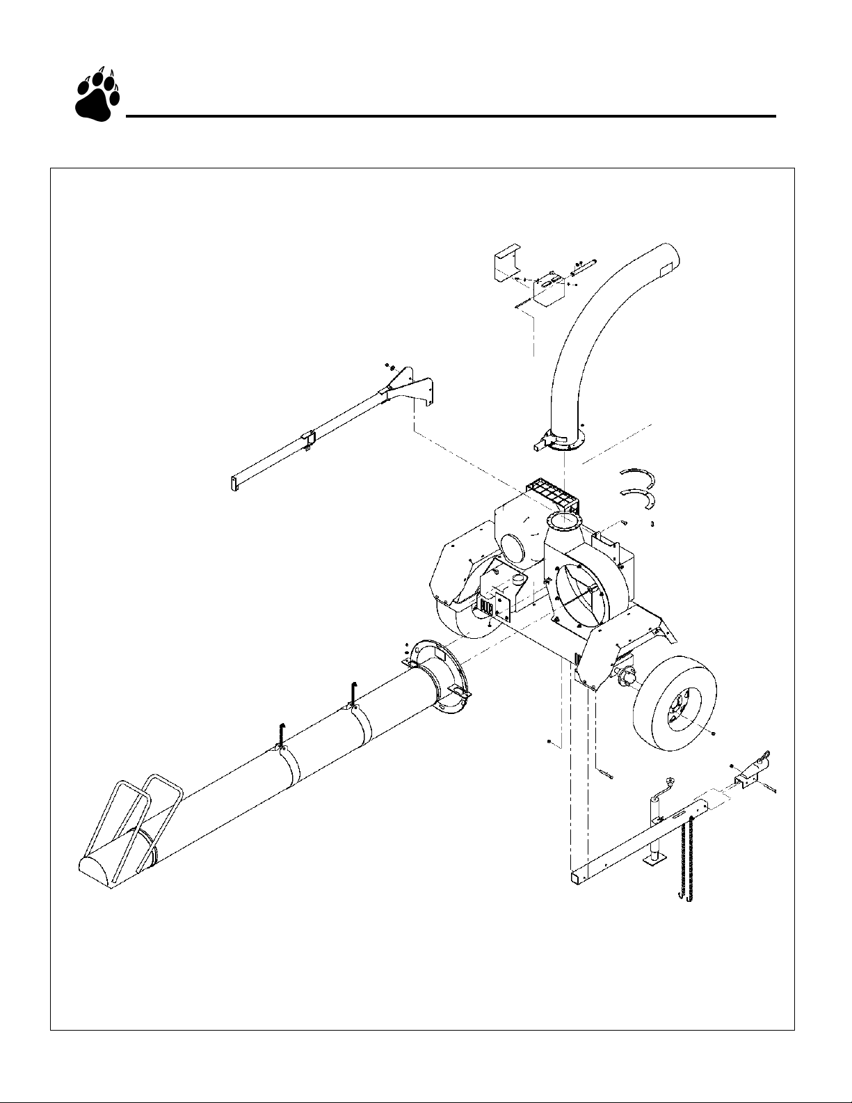
Assembly- Cont.
7
Page 10

Operation
Starting Instructions: 25 HP Engine
NOTE: Normal engine output is 3200 (25 HP) RPMs.
1. Check engine oil level before starting. Add oil if low, but do not overfill.
2. Move choke lever to the ON position. NOTE: the choke may not be needed
if the engine is warm or the air temperature is high.
3. Move the throttle level towards the FAST position approximately 1/2 of the
way.
Release the key if the
engine fails to start
within 10 seconds.
Failure to release starter
will overheat and
possible damage the
starter. Wait 60 seconds
before trying again.
4. Turn the key and release it when the engine starts to allow it to return to the
ON position.
• Release the key if the engine fails to start within 10 seconds. Allow a 60
second cool down period between starting attempts if the engine does not
start. Failure to follow these guidelines can cause permanent damage to the
starter.
• Shut off the starter immediately if it does not turn over the engine. Make no
further attempts to start the engine until the condition is corrected.
5. Gradually move the choke lever to the OFF position as the engine warms.
• Refer to the engine owners manual for additional starting information.
Torque Chart
Standard minimum tightening
torque for normal assembly
applications.
Bolts (SAE GR5)
Size Ft. Lbs.
5/16" 20
3/8" 35
1/2" 75
5/8" 90
Screws
Size Ft. Lbs.
5/16" Set 15
8
Page 11

Operation- Cont.
Vacuuming
The Truck Loader is designed to pick up leaves and other debris then deposit
it in a trailer or truck.
• Keep hands, or any part of body or clothing away from the hose inlet,
discharge chute, or any moving part.
• Maintain proper balance and footing at all times.
• Run unit at full operating speed before starting to vacuum.
• Be careful when vacuuming around gravel, gardens, lawn ornaments, etc.
1. Adjust the discharge tube to the desired loading position before starting.
• The hose inlet vacuums debris as soon as the engine starts.
2. Remove snapper pin to release hose inlet from hose holder weldment.
3. Insert snapper pin into slot in hose holder for safe keeping.
4. Pull flex hose around to the back of the Towable Truck Loader using the
aluminum handles.
Stopping
Unplugging
Danger! The rotor
continues to turn for
sometime after the
engine is shut off.
5. Point the hose inlet towards the debris to remove; use a sweeping motion
to remove debris from a larger area.
• Vacuuming radius is approximately nine (9) feet from the end of the
flex hose.
1. Move the throttle to between half and full throttle.
2. Turn the key to OFF.
• The T owable T ruck Loader is designed to be used in fairly dry conditions.
Wet material along with too much debris and large sticks can plug the
rotor or hose .
• The vacuum loses suction if the flex hose is plugged.
• A plugged rotor bogs down the engine and can possibly stop the engine if
the rotor is severely plugged.
1. Shut off engine and allow rotor to completely stop. Remove spark plug
wire.
2. Remove the access bolt.
3. Turn the access cover to fit the bolts through the slots.
4. Remove the access cover to allow access to the rotor.
5. Clear debris; verify the rotor is unplugged by turning it by hand before
replacing the access cover and bolt.
9
Page 12

Service and Maintenance
Drive Belt
Danger! The rotor
continues to turn for
sometime after the
engine is shut off.
Flex Hose Replacement
Check the condition of the drive belt annually or after 30 hours of operation,
whichever comes first. Replace if cracked, frayed, or worn.
1. Shut off engine and allow rotor to completely stop. Remove spark plug
wire.
2. Remove two bolts holding belt guard in place.
3. Swing belt guard to the side to allow access to the drive belt.
4. Loosen idler tension spring eyebolt.
5. Remove belt from pulleys.
6. Install new belt.
7. Tighten idler tension spring bolt so ther is 1/32" to 1/16" gap between coils.
8. Swing belt guard back to cover belt and secure with bolts.
Check the condition of the flex hose frequently . Replace if split or damaged.
1. Shut off engine and allow rotor to completely stop. Remove spark plug
2. Remove the clamp attaching the hose inlet to the flex hose.
3. Remove the hose inlet.
4. Remove two (2) bolts from the hose wraps to separate the flex hose from the
5. Remove the remaining clamp securing the flex hose to the hose adapter.
6. Install new hose on hose adapter.
7. Complete flex hose replacement by performing steps 1-5 in reverse order.
Trailer Service Tips
1. Check wheel bolt torque every 10 hours of towing use.
2. Check air pressure in tire every 10 hours. Fill to 60 PSI.
3. Check and repack wheel bearings with grease every year.
4. Always connect the safety chains when towing. Check to ensure trailer
5. Check trailer lights.
wire.
swivel boom.
hitch bolts are tight and secure.
10
Page 13

Service and Maintenance- Cont.
Engine Maintenance
Maintenance is essential in preserving engine life. The engine oil should be
checked prior to each start-up. Change oil after first five hours of operation or
within the first month, whichever comes first. Regular oil service period is
every season or 50 hrs. under regular use. Refer to the engine owners manual
for additional oil maintenance information. Service engine according to the
maintenance schedule in your engine owners manual.
Oil Changing Information:
• Shut off the engine. Disconnect the spark plug wire and negative battery
terminal if applicable.
• Change oil while the engine is warm.
• Empty the fuel tank before changing the oil.
• Drain oil by removing drain plug. Refer to engine owners manual for
location.
Place truck loader on a
level surface prior to
filling engine oil.
Refueling Information:
• Refill with new SAE recommended oil.
10W-30, 10W-40, general use if temperature is 0 deg to 100 deg
Kohler “Command”, general use if temperature is 32 deg and above
5W-20, 5W-30, general use if temperature is 32 deg or below
Kohler “Winter”, general use if temperature is 32 deg and below
Please refer to the engine owners manual for specific information regarding engine oil types.
Oil Capacity
25HP Kohler (Model 73725 & 73125) 2.1qts.
• Check oil level. Oil should be at FULL mark or upper limit line.
• Allow engine to cool before refueling.
• Refuel in a well-ventilated area.
• Do not fill above the fuel level mark.
• Clean around fuel fill before removing cap to refuel.
Danger! Gasoline is
highly flammable and
explosive.
Please refer to the engine owners manual for specific fuel recommendations.
Fuel Capacity
25HP Kohler (Model 73725 & 73125) 6.6 gal.
11
Page 14

Service and Maintenance Schedule
Inspection Items
Check Nuts & Bolts (Including Wheels &
Tire Pressure)
Check
Engine Oil
Replace
Replace Spark Plug
Check
Air Filter Element
Replace Fuel Filter
Clean
Replace
Before
Each
Use
Every
10
Hours
Every
25
Hours
Every
50
Hours
*
Interval
Every
100
Hours
Every
200
Hours
Every
300
Hours
**
Every
800
Hours
Every
1
years
Check Drive Belt
Clean Machine
Note: (*) Service more frequently when used in dusty conditions
(**) Replace Paper element type only
Before inspecting or repairing any part of the machine, shut off the engine and make sure all
moving parts have come to a complete stop.
Indicates first hours of use.
12
Page 15

Troubleshooting
Problem Probable Cause Suggested Remedies
1. Engine will not start.
a ) Improper control settings.
b) Lack of fuel.
c) Internal engine problems.
d) Spark plug disconnected.
e ) Dirty, stale, or contaminated
gas.
a) Use proper settings.
b) Fill fuel tank.
c) Contact dealer.
d) Connect spark plug.
e ) Refill gas tank with fresh, clean
unleaded regular gasoline.
2. Engine stalls or stops.
3. Engine overheats.
4. Excessive vibration while
running.
5. Rotor will not turn.
6.Excessive belt wear.
7.Trailer sways during towing.
a) Plugged rotor .
b) V acuuming material too fast
into mchine.
a ) Cooling system plugged.
b) Improper oil level
a) Drive system vibration.
a ) Drive belt too loose or bro-
ken.
b) Plugged rotor .
a ) Not using correct belt.
b) Pulley damaged or wore.
c) Pulley not in alignment.
d) Belt tension too loose.
a) T ire air pressure not correct.
a ) Clear rotor.
b) Slow vacuuming rate.
a ) Clean cooling fan and fins.
b) Fill engine to correct oil level.
Refer to the engine owners manual.
a ) Check drive belts and pulleys for bad or
worn areas.
a ) Adjust or replace.
b) Clear rotor .
a) Contact authorized dealer to order Bear
Cat belts.
b) Replace pulley .
c) Align pulley with straight edge.
d) T ighten belt or replace.
a) Check tire sidewall for inflation limits.
8.Plugged discharge tube.
a) Engine speed too slow .
b) V acuuming too much
material into unit.
a) Increase engine speed.
b) V acuum debris at a slower rate.
13
Page 16

Specifications
Overall Size: 85" x 73" x 97"
Flex Hose Size: 12" dia. x 10ft.
Rotor Size: 19.88" x 7"
Discharge Size: 8" dia.
Chute Rotation: 360 deg.
Drive Type: Belt
Belt Size: 2B70
Weight (lbs.): 1022 lbs. (25 HP T owable)
Wheel Tread: 62"
Tires: 225/75/15
Fuel T ank Capacity (gal.): 6.6
Engine: 25hp gasoline
Specifications are subject to change due to design modifications.
14
Page 17

Specifications
15
Page 18

Limited Warranty
Crary Bear Cat Truck Loaders models 73725 and 73125 are warranted for one year from date of
sale for consumers and one year from the date of sale for commercial or rental operations.
Within the above stated period, Crary Co. will replace any part(s) found to be defective in material
and/or workmanship, after the receipt of the part in our plant. Labor costs to replace these defective parts
will be paid at a Crary established labor rate and time allowed (flat rate) for repair. All transportation
charges incurred in shipping part(s) are the responsibility of the purchaser .
This warranty is void in the case of accidents, failure to perform normal maintenance, or failure
to follow those instructions listed in the service manual. This warranty is also in lieu of all other
expressed warranties and voids any implied warranty as to the merchantability or fitness of the
product for a particular purpose and of any other obligation on the part of Crary Co. Some states do
not allow limitations on how long the implied warranty lasts, so the above limitation may not apply
to you.
This warranty applies only to parts or components which are defective, and does not cover
necessary repair due to normal wear, misuse, accidents, or lack of proper maintenance. This includes belts, pulleys, and flex hose. Regular routine maintenance of the unit to keep it in proper
operating condition is the responsibility of the owner.
All warranty repair reimbursable under the Crary Co. warranty must be performed by an authorized Bear Cat service dealer using Bear Cat approved replacement parts. Repair or attempted repair
by anyone other than an authorized Bear Cat service dealer is not reimbursable under the Crary Co.
warranty. In addition, these unauthorized repair attempts may result in additional malfunction, the
correction of which is not covered by warranty.
Crary Co. is not liable for indirect, incidental, or consequential damages in connection with the
use of this product including any cost or expense or providing substitute equipment or service during
periods of malfunction or non-use.
Some states do not allow the exclusion of incidental or consequential damages, so the above
exclusion may not apply to you. This warranty gives you specific legal rights. You may also have
other rights which vary from state to state.
Be sure to note the vacuum serial number in any correspondence with Crary Co. or any authorized Bear Cat dealer. The serial number is located on the vacuum housing.
Page 19

Crary Company
A Division of TerraMarc Industries
Box 849
West Fargo, ND 58078
(701) 282-5520
FAX: (701) 282-9522
www.crary.com
• (800) 247-7335
 Loading...