

Page 1

9 INCH
MADE WITH PRIDE IN THE...
CHIPPERS
72928 - 28 HP DIESEL HYD
72942 - 42 HP HYD
74950 - 50 HP
OW N E R ' S M A N UAL
PN: 16783 R0900
Companion to 12139
Page 2

Before You Begin
MANUFACTURED BY CRARY INDUSTRIES
MANUFACTURED IN U.S.A.
XXXXXX
WEST FARGO, NORTH DAKOTA 58078 U.S.A.
SERIAL NUMBER
DEAR CRARY BEAR CAT CUSTOMER
Thank you for purchasing a Crary Bear Cat product. The Crary Bear Cat line is designed, tested, and manufactured to give years of
dependable performance. To keep your machine operating at peak efciency, it is necessary to adjust it correctly and make regular
inspections. The following pages will assist you in the operation and maintenance of your machine. Please read and understand this
manual before operating your machine.
If you have any questions or comments about this manual, please call us toll-free at 1-800-247-7335.
If you have any questions or problems with your machine, please call or write your local authorized Crary Bear Cat Dealer.
This document is based on information available at the time of its publication. Crary Bear Cat is continually making improvements
and developing new equipment. In doing so, we reserve the right to make changes or add improvements to our product without
obligation for equipment previously sold.
PLEASE SEND US YOUR WARRANTY CARD
A warranty card is included in your owner's kit packaged with your machine. Please take the time to ll in the information requested
on the card. When you send your completed card to us, we will register your machine and start your coverage under our limited
warranty.
PARTS ORDERING INFORMATION
For service assistance or parts, contact your nearest authorized
Crary Bear Cat dealer or the factory. Your nearest authorized
dealer will need to know the serial number of your machine to
provide the most efcient service. See below for information on
how to identify and record the serial number for your machine.
If you need engine service or parts:
For engine service or parts, contact your nearest authorized
engine dealer. An authorized engine dealer can handle all parts,
repairs, and warranty service concerning the engine.
SERIAL NUMBER LOCATION
Please record the serial number in the space provided and on
the warranty and registration card.
REPLACEMENT PARTS
Only genuine Crary Bear Cat replacement parts should be used
to repair the machine. Replacement parts manufactured by oth-
ers could present safety hazards, even though they may t on
this machine. Replacement parts are available from your Crary
Bear Cat dealer.
Provide the following when ordering parts:
The SERIAL NUMBER of your machine.
The PART NUMBER of the part.
The PART DESCRIPTION.
The QUANTITY needed.
SERIAL NUMBER
HOW TO CO NTA CT CR ARY BE AR CAT
ADDRESS PHONE E-MAIL HOURS
237 NW 12th Street
P.O. Box 849
West Fargo, ND 58078
800-247-7335
701-282-5520
FAX: 701-282-9522
opesales@crary.com
service@crary.com
© 2006, CRARY INDUSTRIES, ALL RIGHTS RESERVED. PRODUCED AND PRINTED IN THE U.S.A.
Monday - Friday,
8 am to 5 pm
Central Time
Page 3

LIMITED WARRANTY
This warranty applies to all AG and Outdoor Power Equipment manufactured by Crary Industries.
Crary Industries warrants to the original owner each new Crary Industries product to be free from defects
in material and workmanship, under normal use and service. The warranty shall extend 1 year from date of
delivery for income producing (commercial) applications and 2 years from date of delivery for non-income
producing (consumer) use of the product. The product is warranted to the original owner as evidenced by a
completed warranty registration on file at Crary Industries. Replacement parts are warranted for (90) days
from date of installation.
ThE WARRANTY REgIsTRATIoN MusT bE coMpLETED AND RETuRNED To cRARY INDusTRIEs
WIThIN 10 DAYs of DELIvERY of ThE pRoDucT To ThE oRIgINAL oWNER oR ThE WARRANTY
WILL bE voID.
In the event of a failure, return the product, at your cost, along with proof of purchase to the selling Crary
Industries dealer. Crary Industries will, at its option, repair or replace any parts found to be defective in material
or workmanship. Warranty on any repairs will not extend beyond the product warranty. Repair or attempted
repair by anyone other than a Crary Industries dealer as well as subsequent failure or damage that may occur
as a result of that work will not be paid under this warranty. Crary Industries does not warrant replacement
components not manufactured or sold by Crary Industries.
This warranty applies only to parts or components that are defective in material or workmanship.
1.
This warranty does not cover normal wear items including but not limited to bearings, belts, pulleys, filters
2.
and chipper knives.
This warranty does not cover normal maintenance, service or adjustments.
3.
This warranty does not cover depreciation or damage due to misuse, negligence, accident or improper
4.
maintenance.
This warranty does not cover damage due to improper setup, installation or adjustment.
5.
This warranty does not cover damage due to unauthorized modifications of the product.
6.
Engines are warranted by the respective engine manufacturer and are not covered by this warranty.
7.
Crary Industries is not liable for any property damage, personal injury or death resulting from the unauthorized
modification or alteration of a Crary product or from the owner’s failure to assemble, install, maintain or operate
the product in accordance with the provisions of the Owner’s manual.
Crary Industries is not liable for indirect, incidental or consequential damages or injuries including but not
limited to loss of crops, loss of profits, rental of substitute equipment or other commercial loss.
This warranty gives you specific legal rights. You may have other rights that may vary from area to area.
Crary Industries makes no warranties, representations or promises, expressed or implied as to the performance
of its products other than those set forth in this warranty. Neither the dealer nor any other person has any
authority to make any representations, warranties or promises on behalf of Crary Industries or to modify the
terms or limitations of this warranty in any way. Crary Industries, at its discretion, may periodically offer limited,
written enhancements to this warranty.
cRARY INDusTRIEs REsERvEs ThE RIghT To chANgE ThE DEsIgN AND/oR spEcIfIcATIoNs
of ITs pRoDucTs AT ANY TIME WIThouT obLIgATIoN To pREvIous puRchAsERs of ITs
pRoDucTs.
Page 4

Contents
Section 1: Safety Instructions .....................................................2
1.2 Safety Decals.................................................................................... 4
Section 2: Assembly, Controls, and Operation..........................5
2.1 Assembly.......................................................................................... 5
2.1.1 Attach the Trailer Wheels............................................................. 5
2.1.2 Attach the Pintle Hitch .................................................................. 5
2.1.3 Attach the Chute Support ............................................................. 6
2.1.4 Attach the Chipper Chute............................................................. 6
2.15 Attach the Chute Extension Tray................................................... 6
2.1.6 Connect the Control Cable .......................................................... 6
2.1.7 Attach the Blower Discharge Tube............................................... 7
2.1.8 Adjusting the Hydrostatic Control Cable ..................................... 7
2.1.9 Before Using................................................................................ 8
2.1.10 Hydraulic Fluids ......................................................................... 8
2.1.11 Prepare Hydraulic System......................................................... 8
2.2 Identification ......................................................................................9
2.3 Operation ........................................................................................ 1 0
2.3.1 Starting: 28 & 50 HP Kubota Model ...........................................10
2.3.3 Starting: 42 HP Ford Model........................................................ 11
2.4 Chipping ..........................................................................................12
2.5 Stopping Instructions....................................................................... 1 2
2.6 Electronic Feed Sensor .............................................................. 13-16
C
ONTENTS
Section 3: Service and Maintenance ........................................17
3.1 Sharpening Chipper Blades ............................................................. 18
3.1.1 Chipping Blade Sharpening Tips .............................................. 18
3.1.2 Setting Chipping Blade Clearance ............................................ 19
3.1.3 Adjusting Drive Belt.................................................................... 19
3.1.4 Replacing Drive Belt .................................................................. 1 9
3.1.5 Clearing Plugged Rotor............................................................. 2 0
3.1.6 Repairing or Replacing Rotor Bearings ................................... 20
3.1.7 Greaseable Bearings ................................................................ 2 0
3.1.8 Trailer Service Tips ....................................................................20
3.2 Hydraulic Feed Maintenance ........................................................... 2 0
3.3 Hydrostatic Pump Troubleshooting .................................................. 20
Troubleshooting..........................................................................21
Specifications ..............................................................................22
Replacement & Maintenance Chart ..........................................
24
Warranty
1
Page 5

S
ECTION
1
Safety Instructions
This chipper is designed and tested to offer
reasonably safe service. However, failure to
operate it in accordance with the following safety
instructions MAY RESULT IN PERSONAL IN-
JURY!
Before Operating
1. Become familiar with the owners manual before
attempting to operate this equipment. See engine
owners manual for additional safety information.
2. Do not allow children to operate this equipment.
3. Do not operate this equipment in the vicinity of
bystanders.
4. Carbon monoxide can be extremely dangerous in
enclosed areas; do not run the machine in an
enclosed area. The exhaust from the engine contains carbon monoxide, which is colorless, odorless,
and tasteless.
5. Do not allow hands, or any part of body or clothing,
inside the feeding chamber, discharge chute, or near
any moving part.
secured. Once every 10 hours of operation, all
screws, nuts, bolts, and other fasteners should be
checked for proper tightness to insure everything is
in proper working condition.
Operation
One of the critical moments in job safety, as well as
chipper safety, is setting up your chipping site so you are
not endangered by traffic and the public is not
endangered by your work. Great care must be taken to
provide adequate warning by way of signage and coning,
if it is necessary to divert vehicle or pedestrian traffic.
A well-prepared traffic plan should include parking off
the highway whenever possible. The work area should
be coned off as soon as the chipper vehicle is stopped.
A void sudden traf fic stoppage or lane diversion. Do not
allow pedestrians to walk through the work area. Make
sure chips or dust do not blow into traffic, parked cars,
or pedestrians.
1. Before starting the machine, make certain that the
cutting chamber is empty.
6. Before inspecting or servicing any part of the
machine, shut off the engine, and make sure all
moving parts have come to a complete stop.
Preparation
1. Obtain and wear safety glasses at all times while
operating the machine. One pair of safety glasses is
provided with each chipper.
2. A void wearing loose-fitting clothing. Never operate
this machine wearing loose clothing particularly if it
has drawstrings which could wrap around or get
caught in the machine.
3. Operate the machine only on a level surface. Do
not operate the machine on a paved, concrete, or
hard gravel surface. Operating on a hard surface
may cause discharged material to rebound and
kickback. It will also cause increased machine
vibration. Increased vibration may cause the machine to move and will promote premature wear of
parts or loosening of fasteners.
4. Before starting the machine, visually check that all
screws, nuts, bolts, and other fasteners are properly
2. When feeding chipable material into the machine, be
extremely careful to exclude pieces of metal, rocks,
bottles, cans, and other foreign objects.
3. If the cutting mechanism strikes any foreign object
or if the machine should start making an unusual
noise or vibration, immediately shut off the engine,
and allow the machine to come to a complete stop.
After machine stops:
a) Inspect for damage.
b) Replace or repair any damaged parts.
c) Check for and tighten any loose parts.
4. Every 10 hours of operation, check the bolts on the
following for correct torque (75 ft. lbs.):
• Hydraulic feed roller bearing
• Hydraulic motor mounting
• Chipper rotor bearing
• Chipper blades
• Rotor paddles
• Chipper anvil
2
Page 6

S
ECTION
1
Failure to maintain proper fastening torque (75 ft.
lbs.) on bolts for the components listed above may
result in severe damage to the chipper and/or
personal injury .
5. Do not allow processed material to build up in the
discharge area; this may prevent proper discharge
and can result in kickback of material through the
feed opening.
6. Do not attempt to operate the chipper with any of
the guards, deflectors, or shrouds removed. Keep
away from moving parts.
7. Keep all guards, deflectors, and shrouds in good
working condition.
8. Always stand clear of the discharge area when
operating this machine.
9. Keep your face and body back from the feed opening.
10. Do not overreach. Keep proper balance and footing
at all times.
1 1. Do not transport or move machine while the ma-
chine is running.
12. If the machine becomes clogged, shut off engine.
Allow machine to come to a complete stop before
clearing debris.
Additional Safety Rules for Towing
1. Before towing, rotate the discharge tube to face in
the opposite direction of the vehicle that is towing it.
This will prevent the discharge tube from projecting
over the trailer wheels and striking foreign objects.
2. Always connect hitch safety chains. Make sure
trailer hitch bolts are tight and secure. Do not
attempt to attach the pintle hitch to a ball type
vehicle hitch.
3. Maximum towing speed should not exceed 55
M.P.H. Inflate tires to manufactures specs. as
stated on the tire sidewall. Check wheel lug bolts
periodically to be sure they are tight and secure.
4. Make sure that the jack stand on trailer is in the UP
position to clear the ground during towing. Place the
jack stand on a level surface and secure it in the
DOWN position before use.
5. Never allow passengers to ride on the infeed chute
while the vehicle is moving, whether the chipper is
running or not.
Maintenance and Storage
1. When this equipment is stopped for servicing,
inspection, storage, or to change an accessory, make
sure that the key is removed from key switch.
Disconnect battery.
2. Store the machine out of the reach of children and
where fuel vapors will not reach an open flame or
spark. For storage periods of three months or more,
drain the fuel and dispose of it in a safe manner.
Always allow the machine to cool before storing.
The Standard muffler installed on the
chipper engine does not include a spark
arrestor. If this machine is to be used in an
area where a spark arrestor is required by
law, one will have to be added before use.
Contact the local authorities to see if these
laws apply to you. See your authorized engine
dealer for spark arrestor options.
3
Page 7

S
ECTION
1
DANGER
1) Become familiar with the Owners Manual before
attempting to operate this equipment.
2) Do not allow children to operate this equipment. Do
not operate this equipment in the vicinity of
bystanders.
3) Carbon Monoxide can be extremely dangerous in
enclosed areas: do not run the machine in an
enclosed area since the exhaust from the engine
contains carbon monoxide.
4) Do not allow hands or any other part of the body or
clothing inside the feeding chamber, discharge chute,
or near any moving part.
5) Before inspecting or servicing any part of the machine,
shut off power source, disconnect the spark plug wire
from the spark plug and make sure all moving parts
have come to a complete stop.
6) Do not transport this machine while the engine is
running.
7) Avoid wearing loose-fitting clothing.
8) Operate the machine only on a level surface. Keep
proper balance and footing at all times. Do not
operate machine on a paved or gravel surface.
9) Before starting the machine, check that all screws,
nuts, bolts and other fasteners are properly secured;
make certain that the cutting chamber is empty. Do
not operate without guards or screens in place.
10) When feeding shreddable material into the equipment,
be extremely careful that pieces of metal, rocks,
bottles, cans or other foreign objects are not included.
11) Obtain and wear safety glasses at all times while
operating machine.
12) If the cutting mechanism strikes any foreign object, or
if the machine should start making any unusual noise
or vibration, immediately shut off the engine and allow
the machine to stop. Disconnect the spark plug wire
from the spark plug and take the following steps:
1) Inspect for damage;
2) Replace or repair any damaged parts;
3) Check for and tighten any loose parts.
13) Keep the engine clean of debris and other
accumulations. Do not tamper with engine governor
settings.
14) Do not allow processed material to build up in the
discharge area; this may prevent proper discharge
and can result in kickback of material through the
discharge opening.
15) Keep all guards and deflectors in place and in good
working condition. Replace any damaged decals.
16) Always stand clear of the discharge area when
operating this machine. Keep face and body back
from the feed opening.
17) If the machine becomes clogged, shut off the engine
(or motor), disconnect the spark plug wire and allow
machine to come to a complete stop before cleaning
debris.
PN 17846
KNIFE ACCESS COVER
DO NOT REMOVE COVER UNLESS
MACHINE IS STOPPED AND SPARK
PLUG WIRE OR DRIVE SHAFT IS
DISCONNECTED. USE ACCESS FOR
KNIFE INSPECTION OR REPLACEMENT
ONLY. DO NOT OPERATE MACHINE
WITH ACCESS COVER REMOVED.
PN 16085
SHIELD HAS BEEN
REMOVED.
DO NOT OPERATE
WITHOUT SHIELD IN
PLACE. SERIOUS
INJURY OR DEATH
MAY OCCUR.
PN 17423
PN 17423
PN 16085
Safety Decals
Safety and instruction decals are located on the chipper frame and engine. Replace any
decal that is damaged or unreadable.
Call dealer for information on decals in Spanish, French, or other languages. For location
of safety decals on the chipper frame, see parts drawings and lists in Parts Manual.
NOTE: For engine safety and instruction decals, see engine owners manual or contact the
engine manufacturer.
PN 17846
PN 16558
PN 12010
PN 16551
4
Page 8
2.1 Assembly
S
ECTION
2
Your chipper may arrive totally or partially assembled. If
your chipper arrives partially assembled, you may need to
perform the steps in this section.
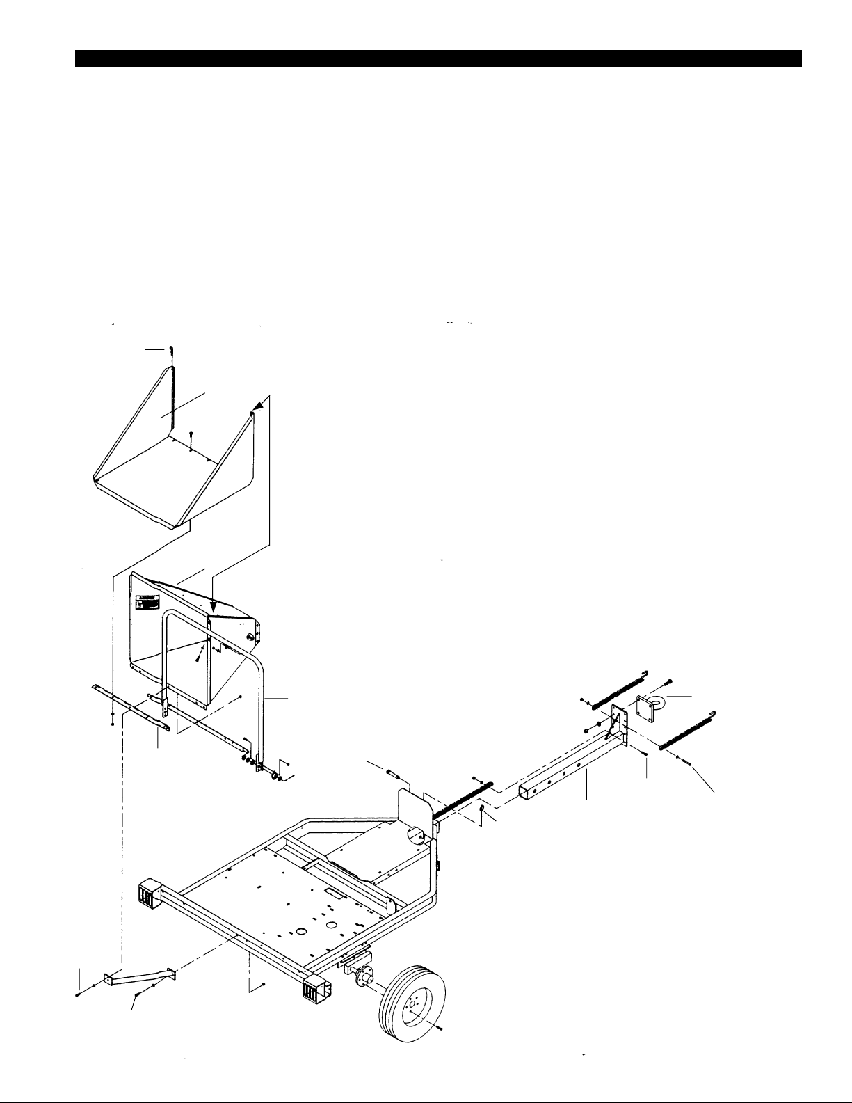
2.1.1 Attach the Trailer Wheels
1. Remove the chipper from its shipping crate. Place the
unit on a level surface before attempting to assemble
it. See the Torque Chart at the bottom of page 8 for
minimum tightening torque of bolts and screws.
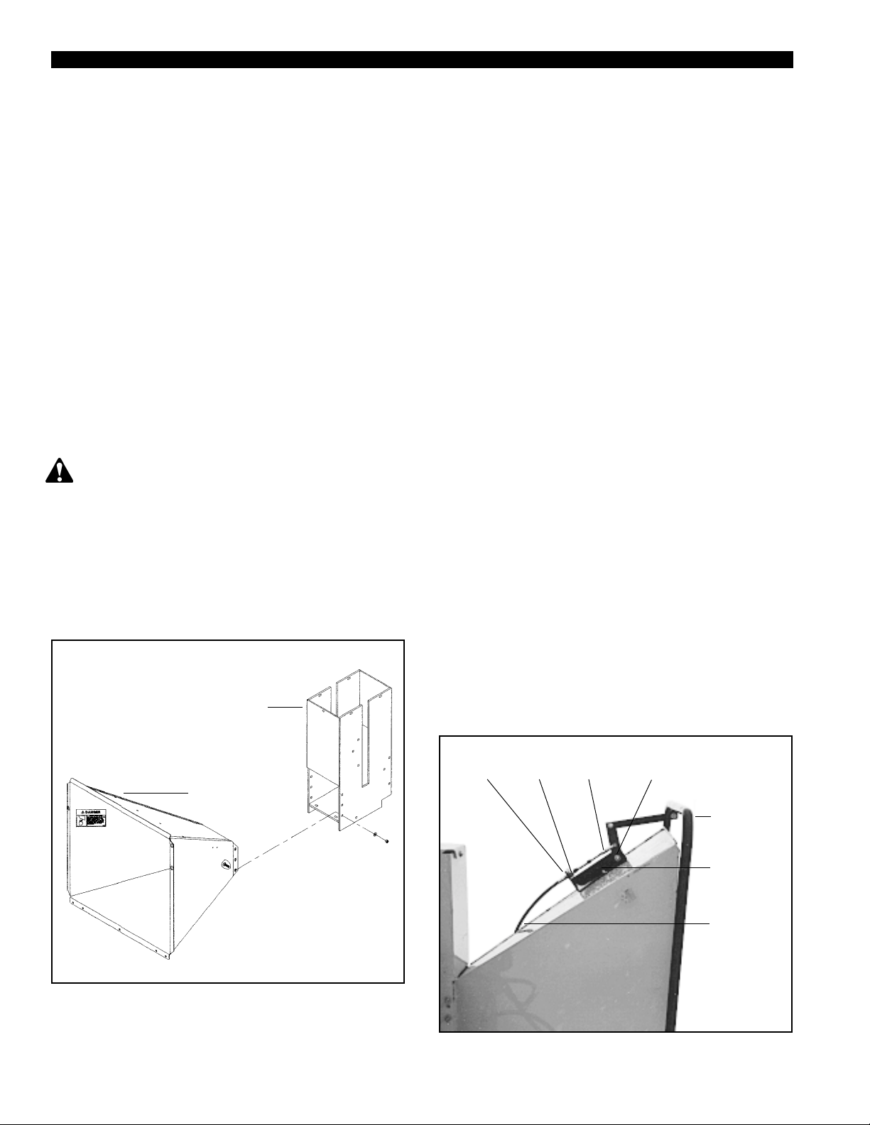
Hairpin Clip
Extension
Tray
Chipper
Chute
Position this lip
behind the lip
on the chipper
chute shown
below. Hold the
extension tray
directly above
the chipper
chute and slide
it downward.
2. Raise the trailer several inches from the ground with a
hoist or jack. Support the chipper securely .
3. Lift one wheel to a hub and align the wheel lug holes
with the hub lug holes (see figure 2.1). Thread the lug
bolts into the holes and tighten the lug bolts to 75 ft.
lbs. Follow a star pattern when tightening the lug
bolts. Repeat this step for the remaining wheel.
2.1.2 Attach the Pintle Hitch
1. Insert the adjustable hitch into the hitch opening in the
chipper trailer. Insert a 3/8" x 2" bolt through the bolt
hole in the adjustable hitch as shown in figure 2.1.
Place the end link in the safety chain welded to the
chipper trailer over the 3/8" bolt end. Secure the chain
with a washer and nut.
2. Attach the pintle hitch eye to the adjustable hitch with
3/8" x 2" bolts, washers, and nuts. T orque the bolts to
90 ft. lbs.
3. Connect the safety chains to the adjustable hitch
3/8" x 1"
Bolt
Extension
Hinge
3/8" x 1-1/4"
Bolt
Feed Control
Lever
Top Link Pin
Figure 2.1
Lynch Pin
Adjustable
Hitch
Weldment
3/8" x 2"
Bolt
Pintle Eye
3/8" x 2-1/2"
Bolt
5
Page 9
S
ECTION
2
weldment as shown in figure 2.1. Use a 3/8" x
2-1/2" bolt, washers, and nut to attach the two
safety chains with hooks as shown.
4. Push the top link pin through the holes in the hitch
and trailer. Secure the top link pin with a lynch pin.
Adjust the hitch to make the chipper trailer as level as
possible when connected to the towing vehicle.
2.1.3 Attach the Chute Support
Attach the chute support to the trailer using one 3/8" x
1-1/4" bolt, washer, and locknut. Refer to figure 2.1.
2.1.4 Attach the Chipper Chute
Do not operate this unit without the chipper chute
correctly installed. Rotating cutting blades can cause
serious personal injury .
Mount the chipper chute to the hydraulic feed using
eight 3/8" x 1" bolts and locknuts. T o insert the top
bolts, you may need to temporarily lift the grab roller
with a pry bar. Use three bolts on each side and two on
the bottom (see figure 2.2).
2.1.5 Attach the Chute Extension Tray
1. After mounting the chute to the hydraulic feed, slide
the chute extension tray over the chipper chute as
shown in figure 2.1. Make sure that you posi-
tion the lip on the extension tray behind the
lip on the chipper chute. Align the five bolt holes
in the chute extension tray with the bolt holes in the
extension hinge.
2. Insert a 3/8" x 1" carriage bolt (included in owners
kit packaged with the chipper) through the two
outside holes on the extension tray and the extension hinge. Secure the bolts with washers and
nuts.
3. Insert one 3/8" x 1" carriage bolt through the end of
the chute support and middle holes on the extension hinge and extension tray. Secure the bolts
with washer and nuts. Secure with hairpin clips.
2.1.6 Connect the Control Cable
1. Remove the clevis assembly from the hydrostatic
control cable end (see figure 2.3). Remove one
nut on the cable end. Insert the cable end into the
hole in the cable anchor weldment. Replace the
nut and the clevis assembly .
2. Attach the clevis assembly to the center hole on
the feed control lever.
3. Adjust the cable detent ball to hold the control arm
is in the forward position or neutral position
detents.
2.1.9 Before Using
Hydraulic
Feed
Insert cable
through hole
Chipper
Chute
Clevis
AssemblyNut
Detent
Ball
Feed
Control
Lever
Cable
Anchor
Weldment
Hydrostat
Control
Cable
Figure 2.2
Figure 2.3
6
Page 10

S
ECTION
2
2.1.7 Attach the Blower Discharge Tube
Attach the blower discharge tube to the mounting flange
on the chipper frame (see figure 2.4). Half of the
mounting clamp is already attached to the tube. Slide the
tube into the flange and tighten the bolts to secure it.
Install the second half of the clamp to the tube and
flange. Rotate the tube 360 degrees and lock it in place
with the handle to make sure it is mounted correctly.
Blower Discharge Tube
2.1.8 Adjusting the Hydraulic Feed
Control Cable
Figure 2.5 shows the hydraulic feed control cable
assembly and the detent position slots. The cable is
attached and adjusted from the factory , but it should
be checked and adjusted as needed before use. The
hydraulic feed control lever has three positions:
Forward (lever moved toward the operator)
Neutral (lever in center position)
Reverse (lever moved away from operator; reverse
has no detent position)
When the operator moves the control lever to the
neutral position, the detent ball should be positioned in
the rear detent slot (see figure 2.5). The feed roller
should come to a complete stop when the control
lever is in the neutral position. If it does not stop,
adjust the clevis assembly on the control cable as
follows:
1. If the control lever is in neutral and the roller
creeps forward, the cable is too short; adjust it to
a longer length.
Figure 2.4
Mounting Clamp
Mounting Flange
2. If the roller creeps in a reverse direction, the
cable is too long; adjust it to a shorter length.
3. Adjust the cable as needed to compensate for
cable stretch.
Clevis Assembly
Forward
Detent
Neutral
Detent
Chipper Chute
Adjust cable here as needed.
Figure 2.5
7
Page 11

S
ECTION
2
1. Install battery (not included: use group 22F 300 CCA
min), connect positive and ground battery cables, and
check battery condition. Charge if needed. Note: If
needed, a larger group UB72 battery may be used.
Use caution when connecting battery cables near
fuel. A spark could ignite the fuel and cause a fire.
2. Fill the engine with oil (per instructions in supplied engine manual) and fill the fuel tank with fuel.
Important! See instructions below, for hydrostatic
pump start-up procedure.
2.1.10 Hydraulic Fluids
Handle pressurized hydraulic fluid carefully. Escaping pressurized hydraulic fluid can have sufficient
force to penetrate your skin causing serious injury.
This fluid may also be hot enough to burn. Serious infection or reactions can develop if proper medical treatment
is not administered immediately.
Premium hydraulic fluids containing high quality rust,
oxidation, and foam inhibitors are required. These include
premium turbine oils, API CD engine oils per SAE J183,
M2C33F or G automatic transmission fluids meeting Allison
C-3 or Caterpillar TO-2, and certain specialty agricultural
tractor fluids.
W arning! Do not start engine unless pump is in neutral or detent position on the cable.
4. Start the engine and run at the lowest possible RPM.
5. Loosen the motor fittings until oil bleeds out to
remove air from the system. Retighten fittings.
6. As air is purged from the unit, the oil level in the
reservoir will drop and bubbles may appear in the
fluid. Refill the reservoir as necessary.
7. Run the feed roller in both directions for several
minutes until any remaining air is purged from the
unit. Refill the reservoir as necessary.
8. Shut down the engine, check for and correct any
fluid leaks, and check the reservoir level. Add fluid
if necessary. The hydrostatic pump is now ready for
operation.
Hydrostatic pressure controlled by the crossover relief
valve is factory set at 1750 PSI. A 2000 PSI shim kit is
available for extreme conditions.
2.1.11 Prepare Hydraulic System
Follow this start-up procedure when starting a new
installation or when restarting an installation in which the
hydrostatic pump has been removed from the system.
The flow from the reservoir to the hydrostatic pump and
the flow returning from the hydrostatic pump are always
the same. Hydraulic fluid can flow either direction between
the hydrostatic pump, crossover relief valve, and motor.
1. Before starting the hydrostatic pump, make sure all
system components (reservoir, fittings, etc.) are clean.
2. Fill the reservoir with recommended hydraulic fluid,
which should be filtered before entering the reservoir.
3. The inlet line leading from the reservoir to the charge
pump must be filled before start-up. Loosen the fitting
at the pump on this inlet line until oil bleeds out.
Figure 2.6 Pump-Component Locations
Torque Chart
Standard minimum
tightening torque for normal
assembly applications.
Bolts (SAE GR5)
Size Ft. Lbs.
5/16" 20
3/8" 35
1/2" 75
5/8" 90
Screws
Size Ft. Lbs.
5/16" Set 15
8
Page 12

S
ECTION
2
2.2 Identification
1. Extension Tray: Assists in feeding chipping
material. Folds for towing.
2. Feed Control Lever: Move the arm forward to
increase the feed rate. Push back to reverse the
feed.
3. Chipper Chute: Feeds materials to the chipper
blades for chipping.
4. Discharge Tube: Chipped material exits through
this tube. Tube is adjustable 360 degrees.
5. Drive Belt Shield: Never remove shields when in
use.
6. Control Panel: Contains the key switch, throttle
control, Murphy switch, gauges, and choke control
(gas engine models only).
7. Fuel Tank: Fuel level indicator is located on top.
8. Pintle Hitch: Always use safety chains when
towing chipper.
9. Pivoting Tongue Jack: Always have in UP
position and clear from ground when moving. When
in use, place in DOWN position on a level surface.
Turn handle to raise or lower wheel.
10. Battery: (Not included.) Use group 22F 300 CCA
min.
11. Clutch Foot Pedal: Used to engage rotor assembly
drive belt.
4
NOTE: Your chipper
may be different
3
2
because of design
modifications at the
time of production.
1
5
7
8
11
6
10
9
9
Page 13

S
ECTION
2
2.3 Operation
2.3.1 Starting: 28 & 50 HP Kubota Model
CAUTION: Move machine to a clear, level area
paved, concrete, or gravel surface. Do not operate
in the vicinity of bystanders. Make sure cutting chamber
is empty before starting.
1. Before starting, fill engine with oil to the correct level.
See engine manual for additional starting, operation,
and maintenance instructions.
NOTE: Some oil usage is normal. Check level with each
use.
WARNING: Handle fuel with care. It is highly
flammable. Always use an approved container and
fill tank outdoors.
2. Before starting, fill fuel tank with fresh, clean diesel
fuel. For instructions on bleeding the fuel system on
initial start up or if fuel runs out, see engine manual.
CAUTION: See operation/start-up decal by foot
clutch pedal on machine before starting.
9. Slowly let foot clutch pedal up. This will engage
drive belt and the rotor will turn. If the engine kills
when engaging the drive belt, release foot clutch
pedal more slowly .
10. When clutch is engaged, the foot pedal may vibrate
or shake until the engine and rotor have increased to
full running RPM (3000 RPM).
Do not move chipper during operation.
CAUTION: Obtain and wear safety glasses at all
times when operating the machine. Do not wear
loose fitting clothing. Use common sense and practice
safety to protect yourself from branches, sharp objects
and other harmful objects.
WARNING: Do not leave machine unattended or
attempt any inspection or service unless the engine
is stopped and the key switch is in OFF position.
3. Turn key switch to preheat position. Hold in preheat
position for several seconds until glow plug indicator
light switches off.
4. Push throttle control in until it stops.
5. Depress foot clutch pedal, this will disengage drive belt
and enable engine to start.
6. Push in and hold Murphy switch push-button. Continue to hold Murphy switch in when cranking engine
until engine is running.
7. Activate the starter switch. Release the switch as
soon as the engine starts. Do not crank over for more
than 10 seconds. Release Murphy switch after engine
is running; hold murphy switch in longer if engine
immediately kills after releasing.
Note: The Murphy switch system will shut the engine off
if the oil pressure is too low or if the engine temperature
is too high. If the engine will not run or shuts of for these
reasons, consult your local dealer.
8. Push center throttle control button in. Increase
throttle control to full throttle. Turn throttle control
knob clockwise to achieve maximum RPM.
Throttle
Murphy
Glow Plug
Indicator
No Charge
Indicator
Switch
Hour Meter
(Optional)
Temperature
Gauge
Pressure
Gauge
Key Switch
10
28 & 50 HP Kubota Chipper Control Panel
Page 14

S
ECTION
2
2.3.3 Starting: 42 HP Ford Models
CAUTION: Move machine to a clear, level area out-
doors before starting. Do not operate machine on a
paved, concrete, or gravel surface. Do not operate in the
vicinity of bystanders. Make sure cutting chamber is empty
before starting.
1. Before starting, fill engine with oil to the correct level.
See engine manual for additional starting, operation, and
maintenance instructions.
NOTE: Some oil usage is normal. Check level with each
use.
WARNING: Handle gasoline with care. It is highly
flammable. Always use an approved container and fill
tank outdoors.
2. Before starting, fill fuel tank with fresh, clean unleaded
regular gasoline.
CAUTION: See operation/start-up decal by foot
clutch pedal on machine before starting.
3. Pull choke control out until it stops.
9. Push choke control in after engine is running smoothly .
After a short shutdown, full choke may not be necessary. If engine fails to start, use partial choke.
10. Slowly let foot clutch pedal up. This will engage drive
belt and the rotor will turn. If the engine kills when engaging the drive belt, release foot clutch pedal more
slowly .
1 1. When clutch is engaged, the foot pedal may vibrate or
shake until the engine and rotor have increased to full
running RPM (3000 RPM).
Do not move chipper during operation.
CAUTION: Wear safety glasses at all times when
operating the machine. Do not wear loose fitting clothing. Practice safety to protect yourself from branches, sharp
objects and other harmful objects.
WARNING: Do not leave machine unattended or at-
tempt any inspection or service unless the engine is
stopped and the key switch is in OFF position.
4. Push center throttle control button in. Position the throttle
control 1/3 of the distance between no throttle and full
throttle.
5. Depress foot clutch pedal, this will disengage drive belt
and enable engine to start.
6. Push in and hold Murphy switch push-button. Continue
to hold Murphy switch in when cranking engine until
engine is running.
Note: The Murphy switch system will shut the engine off if
the oil pressure is too low or if the engine temperature is too
high. If the engine will not run or shuts off for these reasons,
consult your local dealer.
7. Activate the starter switch. Release the switch as soon
as the engine starts. Do not operate the starter for periods longer than 10 seconds at a time. If unit does not
stay running, repeat steps 5, 6, and 7 until the engine is
running smoothly. Release the Murphy switch after
engine is running; hold murphy switch in longer if engine immediately kills after releasing.
8. Push center throttle control button in. Increase throttle
control to full throttle. Turn throttle control knob clockwise to achieve maximum operating RPM (3000 RPM).
If needed, the collar on the cable can be rotated to lock
the cable in position.
Choke
Hour Meter
(Optional)
No Charge
Indicator
Temperature
Gauge
Throttle
Murphy
Switch
Pressure
Gauge
Key Switch
Ford Engine Chipper Control Panel
11
Page 15

S
ECTION
2
2.4 Chipping
The Crary Bear Cat chipper is designed to chip a variety
of materials into a more readily decomposing or handled
condition. The following guidelines can be used to help
you get started.
Please read and follow all safety instructions in this
manual. Failure to operate the chipper in accordance with the safety instructions MAY RESULT
IN PERSONAL INJURY!
1. Be sure the unit is at full operating speed before you
start to chip material.
2. Select limbs that are up to 9 inches in diameter. Trim
side branches that cannot be bent enough to feed into
the chipper chute. Small diameter branches can be
held together in a bundle and fed in simultaneously .
3. Feed brush from the side of the infeed chute, rather
than from the front. Then, step aside to avoid being
hit by the brush moving into the chipper.
4. Never lean over the infeed chute to push objects into
the cutting device. Use a push stick or brush paddle.
5. Never use shovels or forks to push brush. They can
go through the chipper, are expensive to replace and
cause major damage. In addition, metal pieces can
come back like shrapnel to injure or kill.
9. If the chipper jams, reverse the feed by moving the
control arm in the reverse direction. Remove the branch
and rotate it before reinserting it into the chute.
Alternately insert and retract the limb or insert
continuously at a rate that will not kill the engine.
Chipping dead, dry material will create heat and dull
the chipping blades quickly. Alternate greener material with dry material to lubricate the chipping blades
for longer life and better performance. When the
chipping blades become dull, they will require periodic
sharpening. Refer to Service and Maintenance,
"Sharpening Chipper Blades."
2.5 Stopping
Instructions
1. Move throttle to slowest position.
2. Depress foot clutch pedal.
3. Turn key switch to off position.
4. Allow machine to come to a complete stop. Release
the foot clutch pedal to help slow the rotor once the
engine has stopped running.
NOTE: The heavy rotor will continue to turn for some
time after the engine. You can tell that the rotor has
stopped when no noise or machine vibration is present.
6. Never push brush into the infeed chute with your
feet.
7. Engage the hydraulic feed by moving the control arm.
Pull the arm toward you to engage the hydraulic feed
(see figure 2.9). In the forward direction, the feed
rate increases as the arm is moved.
8. Place limb, butt end first, into the chipper chute until it
contacts the hydraulic feed roller and is drawn into
the chipper blades. The actual feed rate of the limb
into the chipper will depend on the type of material
fed, and sharpness of the cutting blades.
If the engine slows to where it may stall, push the
control lever inwards to slow or stop the material
feeding and allow the engine to recover. Pull the lever
out to restart feeding when the engine is back to full
speed.
WARNING: Do not leave machine unattended, or
attempt any inspection or service unless the engine is
stopped and the key is removed from key switch.
Reverse
Neutral
Feed Control
Lever
Forward
Figure 2.9
12
Page 16

2.6 Electronic Feed Sensor Installation Insructions
S
ECTION
2
Warning! Shut off the engine and make sure all
moving parts are completely stopped before
inspecting or servicing the machine.
Installation Instructions: All Models
1. Remove drive shaft joint shield ring (PTO only).
2. Remove upper belt guard. * If the serial number is equal
to or greater than X01249, skip to step # 7.
3. Replace sprocket set screw with the 5/16" x 1-1/2" bolt
provided. (See figure 1)
4. Remove the top cover from the Feed Roller Support
unit.
5. Remove the back cover from the LOF A control, center
it 3-1/2" from the top on the front plate of the Feed
Roller Support housing and mark the position of the
holes.
6. Drill four (4) 1/4" holes as marked.
7. Attach the iso-mounts to the controller back plate with
the bolts and nuts provided.
8. Secure the back plate of the controller to the Feed Roller
Support housing with a washer and two (2) M4-0.7 nuts
per bolt.
9. Replace the Feed Roller Support cover.
10. Attach the LOFA control to the back plate.
(See figure 2)
11. Remove outer and inner plugs from the relief valve.
Both plugs are removed using an Allen Wrench. Install
the solenoid cartridge valve and coil. (See figure 3)
12. Secure the sensor bracket with one of the upper bearing bolts and position it so it aligns with the set bolt.
(See figure 4)
13. Position the the proximatey sensor 1/16" - 1/8" from the
head of the bolt.
Figure 1
13
Page 17

S
ECTION
2
14. Replace the belt guard.
Figure 3
14
1/16" - 1/8" GAP
Figure 4
Page 18

Electrical Installation: PTO Models
1. Attach the chipper to the tractor . Connect the Red positive lead to a +12 Volt DC power source on the tractor.
2. Crimp a ring terminal onto the Black, Ground lead.
3. Drill a 3/16" hole in the PTO stand, close to the solenoid
4. Connect the two-pin connector to the top of the valve
coil.
5. Connect the socket connector to the LOFA control.
6. Secure wiring harness with cable ties as appropriate.
valve, and and secure the ground wire with the #10
self-tapping screw provided.
Electrical Installation: Models 620 & 825
1. Crimp a ring terminal onto the Black, Ground lead.
2. Drill a 3/16" hole in the trailer, close to the solenoid
valve, and and secure the ground wire with the #10
self-tapping screw provided.
3. Connect the two-pin connector to the top of the valve
coil.
4. Crimp a spade connector onto the Red wire in the Feed
Sensor harness and connect to the Yellow wire from
the Kohler engine harness .
5. Connect the socket connector to the LOFA control.
6. Secure wiring harness with cable ties as appropriate.
Electrical Installation: Models 928, 942, 950
1. Crimp a ring terminal onto the Black, Ground lead.
2. Drill a 3/16" hole in the trailer, close to the solenoid
valve, and and secure the ground wire with the #10
self-tapping screw provided.
4. Crimp a ring terminal to the Red wire in the Feed Sensor harness and attach to "B" terminal on the back of
the Murphy Switch.
5. Connect the socket connector to the LOFA control.
3. Connect the two-pin connector to the top of the valve
coil.
Electronic Feed Parts List (PN 73244)
PN
12813 Harness, Auto Feed 1
15602 W asher, #6 SAE Flat 4
15640 Nut, M4-0.7 ZP Hex 8
12674 LOFA Hydraulic Control 1
73242-12 Bracket, Proximity Sensor 1
12828 Connector, #10 Insulated Ring 2
12829 Connector, #10 Insulated Fork 3
Description
Qty
.
6. Secure wiring harness with cable ties as appropriate.
PN
12830 Connector, .25 Insulated Male 2
17320 Nyl Cable Tie 4
16967 V alve, Solenoid Cartridge 1
16968 Coil, Solenoid V alve 1
15282 Bolt, 5/16x1-1/2 GR5 Hex 1
15225 Screw, #10x3/4 Hex T ap 1
Description
Qty
.
15
Page 19

Feed Sensor Programming Instructions
Step 1. Initiating Program Mode
1. Hold down the "S" button while turning the engine key to the "on" position until "L" starts to flash on the LCD.
Step 2. Enter Low (L=Low) RPM
The low setting is the RPM speed where the feed roller stops. The "up" arrow increases the RPM setting, while
the "down" arrow decreases the RPM setting. Setting the speed lower causes the engine to lug down more before
the feed roller stops.
1. Hold the appropriate (either up or down) arrow until the desired RPM speed is displayed. (Recommend 1375
rpm.)
2. Push the "S" button once with the desired RPM setting displayed to save.
NOTE: Do not choose a setting equal to or below zero.
Step 3. Enter Normal (N=Normal) RPM
The normal setting is the RPM speed the chipper rotor usually turns.
1. Hold the appropriate (either up or down) arrow until the desired RPM speed is displayed.(Recommend 1500
rpm.)
2. Push the "S" button once with the desired RPM setting displayed to save.
Step 4. Enter High (H=High) RPM
The high setting is not needed with this application.
1. Set to zero to deactivate.
2. Push the "S" button once with zero displayed to save.
Step 5. Enter Return (rEt=Return) RPM
The return setting is the RPM speed where the feed roller restarts. The feed roller should restart before the rotor
reaches "normal" RPM to maximize chipper efficiency. Setting the speed higher allows the engine to recover
more before the feed roller restarts.
1. Hold the appropriate (either up or down) arrow until the desired RPM speed is displayed.(Recommend 1400
rpm.)
2. Push the "S" button once with the desired RPM setting displayed to save.
Step 6. Enter Number of Poles (IPU=Number of Poles)
The number of poles is used to indicate the number of speed pickup devices.
1. Hold the appropriate (either up or down) arrow until one (1) is displayed.
2. Push the "S" button one with one (1) displayed to save.
NOTE: When approaching the end of a log, it might be necessary to manually override the
automatic feed sensor. Be sure to pay attention to the engine speed and feeding of the material.
16
Page 20

3.0 Service and Maintenance
S
ECTION
3
Inspection Items
Check Nuts & Bolts
Engine Oil Level
Change Engine Oil
Replace Oil Filter Cartridge
Check Hydraulic Fluid Level
(3 Gallons)
Replace Air Filter Element
Replace Fuel Filter
Before
Each
Use
Every
10
Hours
Every
25
Hours
Every
50
Hours
Interval
Every
100
Hours
Every
200
Hours
Every
400
Hours
Every
800
Hours
Every
1
years
Check Sharpness of Chipper Blades
Grease Bearings and Pivots
Check Bolts: Chipper Blade, Feed Roller,
Chipper Anvil, Rotor Paddles
Check Drive Belt
Hydraulic Control Cable
(Feed Roller)
Check Water Level
Clean Machine
Indicates first hours of use.
17
Page 21

S
ECTION
3
WARNING: Before inspecting or servicing any part
of the machine, shut off the engine, and make sure
all moving parts have come to a complete stop. The chipping blades are sharp! Use care when working on machine to avoid injury.
WARNING: The rotor assembly has a lock mecha-
nism. When working on the rotor assembly, use the
lock mechanism at all times. Remove the plastic bearing
cover beside the chipper chute. There is a hole in the rotor
shaft and a matching hole in the bracket mounted to the
rotor bearing front side. Install a punch through the rotor
shaft and bracket to lock the rotor in place.
Check the engine oil, and change the oil and filter as recommended in the manual. Service and replace the air
cleaner as recommended.
3.1
Sharpening Chipper Blades
The chipper blades will eventually become dull, making
chipping difficult. The chipper blades are two edged. When
the first edge dulls, flip the blade to use the sharp second
edge. After both edges are dull, sharpen the chipper blades.
It is recommended that the chipper blades are sharpened
every 5-15 hours of chipper operation. To remove the
chipping blades for sharpening:
Use short grinding times and cool with water. T ry to remove
an equal amount off each blade to maintain balance.
Replace the chipping blades and tighten bolts to 75 ft. lbs.
Close cover and replace bolts.
3.1.1 Chipping Blade Sharpening Tips
Poor chipping performance is usually a result of dull chipping
blades. If your chipper's performance has decreased,
check for the following symptoms:
• Severe vibration when feeding material into the chipper.
• Small diameter branches do not self-feed.
• Chips discharge unevenly or have stringy tails–especially when chipping green branches.
Before you sharpen the chipping blades, check for
permanent damage. Replace the blade if:
• The blade is cracked (especially around the bolt holes)
or the edges are too deeply chipped to be ground
smooth.
1. Remove the two 3/8 inch retaining bolts holding access cover to main frame assembly.
2. Tilt access cover over to allow rotor access. Rotate
the rotor so that the bolts holding a chipping blade are
most accessible.
3. Remove the two allen head bolts holding the blade
itself. Repeat for all four blades. The four chipping
blades have two edges per blade and can be reversed
one time each before sharpening. If both sides have
not been used, remove and reverse the chipping blades.
Reinstall chipping blades and proceed with chipping.
T o grind the angled edge of the chipping blade to 45 degrees
(see figure 3.1): Grind the blades on a slow-speed wet
grinder if possible, or have them sharpened by a
professional. If you use a bench grinder, be careful when
grinding so that the blade material does not get too hot and
change color–this will remove the blade's special heat
treated properties.
0.38
Sharpening
Edges
45
Figure 3.1
°°
°
°°
18
Figure 3.2
Page 22

S
ECTION
3
• The base of the cutting edge is worn or has been re-
sharpened so that it is too close to the rotor chipping
slot.
3.1.2 Setting Chipping Blade Clearance
The four chipping blades should clear the chipper anvil
located directly under the chipper chute by 1/16 inch to
1/8 inch. The chipper anvil is adjustable and reversible.
To adjust:
1. Lift rotor access cover and expose rotor (see figure
3.2). Loosen the three 1/2 inch bolts that hold the
chipper anvil to the frame (see figure 3.3).
2. Measure the amount of clearance between chipping
blade and chipper anvil from inside of housing.
3. Adjust inward or outward to desired measurement.
4. Tighten bolts on chipping block to 75 ft. lbs. and
resume operation.
If chipper anvil edge is damaged or worn unevenly,
remove the three bolts holding the anvil and use one of
the other three edges. Adjust for correct measurement.
3.1.3 Adjusting Drive Belt
Check the condition of the drive belt annually or after
every 25 hours of operation, whichever comes first. If
the belt is cracked, frayed, worn, or stretched, replace it.
Only replace belt with original banded type belt, do not use
single type belts. To adjust the belt, proceed as follows:
1. Depress foot clutch pedal. Shut engine off and
disconnect battery cables.
2. Remove large belt guard (three 5/16 inch bolts).
3. Adjust the eyebolt that anchors the idler spring to
adjust the belt tension. Tighten the eyebolt until the
belt deflection at the center of the belt is 7/16" when
a 20 lb. load is placed against the belt (see figure 3.4).
4. Replace belt guard.
5. Start engine and test belt for looseness. Replace the
belt if no adjustment is left.
3.1.4 Replacing Drive Belt
1. Remove large belt guard (three 5/16" bolts).
2. Loosen bolts on hydraulic pump and remove belt.
Chipper Anvil
Rotor Housing
Spacer
3. Lift belt idler pulley off drive belt and remove drive
belt from pulleys.
4. Install new belt on pulleys and lower belt idler.
Check alignment of pulleys and adjust if needed.
5. Check belt tension before start-up. Adjust the
eyebolt that anchors the idler spring to adjust the belt
tension. Tighten the eyebolt until the belt deflection
at the center of the belt is 7/16" when a 20 lb. load is
placed against the belt (see figure 3.4).
7/16" Deflection
(20 lbs.)
Figure 3.3 Figure 3.4
19
Page 23

S
ECTION
3
6. Replace hydraulic pump belt. Readjust hydraulic
pump belt tension by sliding the hydraulic pump in
the mounting slots. Tighten bolts.
7. Replace belt guard.
8. Depress foot clutch pedal, start engine, release foot
clutch pedal to engage belt, and test unit. Readjust
pulleys and belt tension if needed.
3.1.5 Clearing Plugged Rotor
WARNING: If the machine becomes plugged,
depress foot clutch pedal, shut off the engine, and
allow the machine to come to a complete stop before
clearing debris. Do not operate the machine without
proper guards and screens in place.
Feeding too much chipable material at once may plug the
chipper. To clear plugged rotor, proceed as follows:
1. Depress foot clutch pedal and stop engine. Release
foot clutch pedal when engine is stopped.
2. Remove the two 3/8" retaining bolts holding the
access cover to the main frame assembly.
WARNING: The rotor assembly has a lock
mechanism. When working on the rotor assembly ,
use the lock mechanism at all times. Remove plastic
bearing cover under the chipper chute. There is a hole in
the rotor jack shaft and a matching hole in the bracket
mounted to the rotor bearing front side. Install a punch
through the rotor shaft and bracket to lock the rotor in
place.
5. If a rotor bearing needs repair, it is best to remove
the complete rotor assembly from chipper frame.
6. Using an overhead hoist or lifting device, remove the
four 1/2 inch bolts on each rotor bearing and lift the
rotor assembly completely out of the frame. The
complete rotor assembly is 275 lbs.
7. Once the rotor assembly is out of the frame, both
bearings can be removed by a puller and replaced
on the shaft.
8. Use the overhead hoist or lifting device to return the
complete rotor assembly to the chipper frame.
9. Install the four 1/2 inch bolts on each bearing to
secure them to the frame. Tighten bolts to 75 ft. lbs.
3. Lift up rotor access cover.
4. Clean the debris out of the chipper rotor. Turn the
rotor by hand to be sure it is free to rotate.
DANGER: Blades are sharp; avoid contact with
chipper blades.
5. Close rotor access cover and replace bolts.
6. Depress foot clutch pedal, and start engine. Release
foot clutch pedal when engine is running to engage
drive belt. Resume operation.
3.1.6 Repairing or Replacing Rotor
Bearings
1. Remove the two 3/8 inch retaining bolts holding
access cover to main frame assembly. Tilt access
cover over to allow rotor access.
2. Remove large belt guard (three 5/16 inch bolts).
3. Loosen bolts on hydraulic pump and remove hydraulic pump belt. Using the push bolts from the bushing,
remove the bushing and pulley from the rotor shaft.
10. Replace drive belt on pulleys and lower belt idler .
Check alignment of pulleys and adjust engine if
needed.
11. Check belt tension before start-up. Adjust the
eyebolt that anchors the idler spring to adjust the belt
tension. Tighten the eyebolt until the belt deflection
at the center of the belt is 7/16" when a 20 lb. load is
placed against the belt (see figure 3.4, page 15).
12. Close cover and replace bolts.
13. Replace hydraulic pump belt. Readjust hydraulic
pump belt tension by sliding the hydraulic pump in
the mounting slots. Tighten bolts.
14. Replace belt guard and resume operation.
15. Depress foot clutch pedal, start engine, release foot
clutch pedal to engage belt, and test unit. Readjust
pulleys and belt tension if needed.
4. Lift belt idler pulley off drive belt and remove belt
from pulleys. Using the push bolts from the bushing,
remove the bushing and pulley from the rotor shaft.
20
Page 24

S
ECTION
3
3.1.7 Greaseable Bearings and Pivots
The chipper has five greaseable bearings and pivots that
require grease every 50 hours:
• Two bearings on the rotor shaft.
• One greaseable bushing on the foot pedal pivot.
• One grease zerk on idler pivot.
• One grease zerk on discharge chute.
Service engine according to engine manual. Change
engine oil and filter as recommended in manual.
3.1.8 Trailer Service Tips
1. Check wheel bolt torque every 10 hours of towing use.
2. Check air pressure in tires every 10 hours of towing.
3. Check and repack wheel bearings with grease every
12 months.
4. When towing, always connect the safety chains.
Make sure trailer hitch bolts are tight and secure.
5. Check trailer lights.
3.2 Hydraulic Feed Maintenance
NOTE: Check the reservoir daily for proper fluid level,
the presence of water (noted by a cloudy to milky
appearance, or free water in bottom of reservoir), and
rancid fluid odor (excessive heat).
The hydrostatic pump normally does not require regular
fluid changes. The system filter should be changed at
250 hour or annual intervals. The fluid and filter should
be changed and system cleaned if the fluid becomes
contaminated with foreign matter (water, dirt, grease,
etc.) or if the fluid has been subjected to temperature
levels greater than the maximum recommended.
There is a greaseable bearing on each side of the shaft
on the hydraulic feed housing. Grease periodically.
3.3 Hydrostatic Pump Troubleshooting
Symptom
Will not attain normal feed rate.
Will not feed when control arm
is moved.
Feed rate is sluggish under
load.
Hydraulic Feed will not pull in
logs over 4" in diameter, or
continuously stalls or stops.
Probable Cause
Engine not operating at correct speed.
Control linkage damaged or
binding.
Bypass valve stuck partially
open. (Problem in one direction only.)
Control linkage damaged or
not connected.
Drive between engine and
pump damaged.
Pump low on fluid.
Loose drive belt between
engine and pump.
Pump low on fluid.
Large amount of water in hydraulic fluid (evaporates
when hot, resulting in low fluid
level).
Hydraulic system overloading
and causing system to go
over relief.
Suggested Remedy
Repair engine governor.
Repair control linkage.
Repair bypass valve.
Remove foreign material from
valve.
Repair or reconnect control
linkage.
Repair drive (replace broken
belt, repair sheared key, repair splined coupling, etc.).
Refill reservoir. Purge air from
transmission.
Tension drive belt (replace if
necessary).
Refill reservoir. Purge air from
transmission if necessary.
Drain fluid from reservoir and
unit, replace filter element,
and refill with new fluid.
Check relief pressure in system with a pressure gauge
rated to 2500 psi. (System set
by factory at 1750 psi.)
Caution: Hydraulic systems contain
fluid under high pressure. Never check
for leaks with your hands. Relieve
pressure before disconnecting any
hydraulic lines.
Before servicing or
repairing any of the
hydrostatic feed
components (pump,
motor, and/or relief
valve), contact your
dealer or factory
service department.
Warranty on these
items may be void
without prior
authorization.
21
Page 25

T
ROUBLESHOOTING
Troubleshooting
Problem
1. Rotor does not turn
2. Hard to feed chipper
or excessive power
needed to chip
3. Chipper requires
excessive power or
stalls
4. Drive belts squealing
or smoking
5. Vibration while
running
6. Engine dies or runs
poorly
Probable Cause
a) Obstructed
discharge
b) Plugged rotor
a) Obstructed
discharge
b) Dull chipper blades
c) Improper blade
clearance
a) Obstructed
discharge
b) Plugged rotor
c) Green material will
not discharge
a) Plugged rotor
b) Loose or worn belts
a) Drivehead vibration
b) Rotor out of balance
a) Engine problems
Suggested
Remedies
a) Use branch or
similar object to
clear discharge
b) Clear rotor
a) Use branch or
similar object to
clear discharge
b) Sharpen blades
c) Adjust clearance
a) Use branch or
similar object to
clear discharge
b) Clear rotor , feed
material into
shredder more
slowly
c) Alternately feed dry
material, or allow
material to dry
a) Clear rotor
b) Adjust belt tension
or replace belts if
needed
a) Check drive belts
and pulleys for bad
or worn spots.
b) Inspect rotor for
broken or missing
chipper blades and
paddles. Repair if
needed.
c) Check rotor to see if
it wobbles
d) Check to see if rotor
is assembled
correctly
a) Contact local engine
service center
Reference
Service and Maintenance
Service and Maintenance
Service and Maintenance
Service and Maintenance
Service and Maintenance
Engine Manual
22
Page 26

Specifications
S
PECIFICATIONS
Overall Size (LxWxH)
Max. Chipper Cap. (dia.)
Chipper Blade Qty .
Rotor Speed
Rotor Size
Rotor Weight
Rotor Shaft Diameter
Discharge Size
Drive Type
Belt Size
Weight (Lbs.)
Model 72928
119" x 79" x 89"
9"
4 Reversible T ool Steel
1500 RPM
30" Dia. x 1.25"
275 lbs.
1.75"
8"
Belt
3B83
2486
Model 72942
119" x 79" x 89"
9"
4 Reversible T ool Steel
1500 RPM
30" Dia. x 1.25"
275 lbs.
1.75"
8"
Belt
3B85
2540
Model 74950
119" x 79" x 89"
9"
4 Reversible T ool Steel
1500 RPM
30" Dia. x 1.25"
275 lbs.
1.75"
8"
Belt
3B89
2736
Wheel Base
Tire Size
Fuel T ank Cap. (Gal.)
Engine
68"
P215/75R15
18
Kubota 28hp Diesel
68"
P215/75R15
18
Ford 42hp Gasoline
68"
P215/75R15
18
Kubota 50hp Diesel
Specifications are subject to change because of design modifications.
23
Page 27

S
ECTION
3
Replacement & Maintenance Chart
Note: When ordering replacement parts, be sure to identify the
Model and Serial number of the machine.
Replacement Parts Ordered
Date Part Ordered
Date Part Replaced
Replaced By
Checked By
24
Page 28

Declaration of Conformity
The undersigned manufacturer:
Crary Industries, Inc.
237 NW 12
P.O. Box 849
West Fargo, ND 58078-0849
Declares that hereunder specified unit:
CHIPPER
Brand: Crary Bear Cat
Type: Engine driven Chipper
Model Number: 72928S
Complies with the requirements of:
Machinery Directive 2006/42/EC
EN 13525:2005-Forestry Machinery-Wood Chippers -Safety
Emission of Gaseous and Particulate Pollutants Directive 2002/88/EC
EN ISO 12,100, Part 1-Safety of Machinery-Basic Conce pt s, General Principles for Design
EN 982 – Safety of Machinery–Requirements for Fluid Power Systems & their Components-Hydraulics
Noise Emissions Directive 2000/14/EC
-Conformity Assessment Procedure: Annex V
(Use of harmonized standard EN ISO 37 4 4:20 1 0)
Sound Power Level: 95 dB L
Guaranteed Sound Power Level: 112 dB LWA
72928S Serial number Y03136 and up
72928S VIN number 5VJAA00107W000147 and up
West Fargo, ND 58078-0849
June 29, 2011
CRARY INDUSTRIES, INC. The authorized representative in Europe who is authorized to
compile the technical file:
Company: Atlantic Bridge Limited
Address: Atlantic House, PO Box 4800
Earley, Reading RG5 4GB, United Kingdom
______________________________
Arlan Mathias Mr. Phillip Wicks
Senior Project Engineer
PA
th
Street
Data contained in this document pertains only to machines sold in areas that require CE compliance
standards. To identify if your machine is CE compliant, it will have the following CE mark decal:
Page 29

Declaration of Conformity
The undersigned manufacturer:
Crary Industries, Inc.
237 NW 12
P.O. Box 849
West Fargo, ND 58078-0849
Declares that hereunder specified unit:
CHIPPER
Brand: Crary Bear Cat
Type: Engine driven Chipper
Model Number: 74950S
Complies with the requirements of:
Machinery Directive 2006/42/EC
EN 13525:2005-Forestry Machinery-Wood Chippers -Safety
Emission of Gaseous and Particulate Pollutants Directive 2002/88/EC
EN ISO 12,100, Part 1-Safety of Machinery-Basic Conce pt s, General Principles for Design
EN 982 – Safety of Machinery–Requirements for Fluid Power Systems & their Components-Hydraulics
Noise Emissions Directive 2000/14/EC
-Conformity Assessment Procedure: Annex V
(Use of harmonized standard EN ISO 3744:2010)
Sound Power Level: 95 dB L
Guaranteed Sound Power Level: 112 dB LWA
74950S Serial number Y03238 and up
74950S VIN number 5VJAA00157W000136 and up
West Fargo, ND 58078-0849
June 29, 2011
CRARY INDUSTRIES, INC. The authorized representative in Europe who is authorized to
compile the technical file:
Company: Atlantic Bridge Limited
Address: Atlantic House, PO Box 4800
Earley, Reading RG5 4GB, United Kingdom
______________________________
Arlan Mathias Mr. Phillip Wicks
Senior Project Engineer
PA
th
Street
Data contained in this document pertains only to machines sold in areas that require CE compliance
standards. To identify if your machine is CE compliant, it will have the following CE mark decal:
Page 30

Crary Bear Cat
237 NW 12th Street, West Fargo, ND 58078-0849
Phone: 701.282.5520 • Toll Free: 800.247.7335
Fax: 701.282.9522
E-mail: service@crary.com • opesales@crary.com
www.BearCatProducts.com
 Loading...