

Page 1

MADE WITH PRIDE IN THE...
9 INCH
CHIPPER
72928 - 28 HP KUBOTA
72928S - 28 HP KUBOTA
74950 - 50 HP KUBOTA
74950S - 50 HP KUBOTA
CH911DH - 28 HP KUBOTA
CH922DH - 50 HP KUBOTA
OWNER'S MANUAL
Manual P/N 16783
R051107
Companion to P/N 12139
72928 & 74950 VIN: 5VJAA00127W000031 - 5VJAA00117W000571
CH911DH & CH922DH VIN: 5VJAA00127W000255 - 5VJAA00158W000655
Page 2

Before You Begin
MANUFACTURED BY CRARY INDUSTRIES
MANUFACTURED IN U.S.A.
XXXXXX
WEST FARGO, NORTH DAKOTA 58078 U.S.A.
SERIAL NUMBER
DEAR ECHO BEAR CAT CUSTOMER
Thank you for purchasing an ECHO Bear Cat product. The ECHO Bear Cat line is designed, tested, and manufactured to give years
of dependable performance. To keep your machine operating at peak efciency, it is necessary to adjust it correctly and make regular inspections. The following pages will assist you in the operation and maintenance of your machine. Please read and understand
this manual before operating your machine.
If you have any questions or comments about this manual, please call us toll-free at 1-800-247-7335.
If you have any questions or problems with your machine, please call or write your local authorized ECHO Bear Cat Dealer.
This document is based on information available at the time of its publication. ECHO Bear Cat is continually making improvements
and developing new equipment. In doing so, we reserve the right to make changes or add improvements to our product without
obligation for equipment previously sold.
PLEASE SEND US YOUR WARRANTY CARD
A warranty card is included in your owner's kit packaged with your machine. Please take the time to ll in the information requested
on the card. When you send your completed card to us, we will register your machine and start your coverage under our limited
warranty.
PARTS ORDERING INFORMATION
For service assistance or parts, contact your nearest authorized
ECHO Bear Cat dealer or the factory. Your nearest authorized
dealer will need to know the serial number of your machine to
provide the most efcient service. See below for information on
how to identify and record the serial number for your machine.
If you need engine service or parts:
For engine service or parts, contact your nearest authorized engine dealer. An authorized engine dealer can handle all parts,
repairs, and warranty service concerning the engine.
SERIAL NUMBER LOCATION
Please record the serial number in the space provided and on
the warranty and registration card.
REPLACEMENT PARTS
Only genuine ECHO Bear Cat replacement parts should be
used to repair the machine. Replacement parts manufactured
by others could present safety hazards, even though they may
t on this machine. Replacement parts are available from your
ECHO Bear Cat dealer.
Provide the following when ordering parts:
The SERIAL NUMBER of your machine.
The PART NUMBER of the part.
The PART DESCRIPTION.
The QUANTITY needed.
SERIAL NUMBER
HOW TO CONTACT ECHO BEAR CAT
ADDRESS PHONE E-MAIL HOURS
237 NW 12th Street
P.O. Box 849
West Fargo, ND 58078
*Original Instructions
© 2006, CRARY INDUSTRIES, ALL RIGHTS RESERVED. PRODUCED AND PRINTED IN THE U.S.A.
800-247-7335
701-282-5520
FAX: 701-282-9522
sales@bearcatproducts.com
service@bearcatproducts.com
Monday - Friday,
8 am to 5 pm
Central Time
Page 3

LIMITED WARRANTY
This warranty applies to all AG and Outdoor Power Equipment manufactured by Crary Industries.
Crary Industries warrants to the original owner each new Crary Industries product to be free from defects
in material and workmanship, under normal use and service. The warranty shall extend 1 year from date of
delivery for income producing (commercial) applications and 2 years from date of delivery for non-income
producing (consumer) use of the product. The product is warranted to the original owner as evidenced by a
completed warranty registration on file at Crary Industries. Replacement parts are warranted for (90) days
from date of installation.
THE WARRANTY REGISTRATION MUST BE COMPLETED AND RETURNED TO CRARY INDUSTRIES
WITHIN 10 DAYS OF DELIVERY OF THE PRODUCT TO THE ORIGINAL OWNER OR THE WARRANTY
WILL BE VOID.
In the event of a failure, return the product, at your cost, along with proof of purchase to the selling Crary
Industries dealer. Crary Industries will, at its option, repair or replace any parts found to be defective in material
or workmanship. Warranty on any repairs will not extend beyond the product warranty. Repair or attempted
repair by anyone other than a Crary Industries dealer as well as subsequent failure or damage that may occur
as a result of that work will not be paid under this warranty. Crary Industries does not warrant replacement
components not manufactured or sold by Crary Industries.
This warranty applies only to parts or components that are defective in material or workmanship. 1.
This warranty does not cover normal wear items including but not limited to bearings, belts, pulleys, filters 2.
and chipper knives.
This warranty does not cover normal maintenance, service or adjustments.3.
This warranty does not cover depreciation or damage due to misuse, negligence, accident or improper 4.
maintenance.
This warranty does not cover damage due to improper setup, installation or adjustment.5.
This warranty does not cover damage due to unauthorized modifications of the product. 6.
Engines are warranted by the respective engine manufacturer and are not covered by this warranty.7.
Crary Industries is not liable for any property damage, personal injury or death resulting from the unauthorized
modification or alteration of a Crary product or from the owner’s failure to assemble, install, maintain or operate
the product in accordance with the provisions of the Owner’s manual.
Crary Industries is not liable for indirect, incidental or consequential damages or injuries including but not
limited to loss of crops, loss of profits, rental of substitute equipment or other commercial loss.
This warranty gives you specific legal rights. You may have other rights that may vary from area to area.
Crary Industries makes no warranties, representations or promises, expressed or implied as to the performance
of its products other than those set forth in this warranty. Neither the dealer nor any other person has any
authority to make any representations, warranties or promises on behalf of Crary Industries or to modify the
terms or limitations of this warranty in any way. Crary Industries, at its discretion, may periodically offer limited,
written enhancements to this warranty.
CRARY INDUSTRIES RESERVES THE RIGHT TO CHANGE THE DESIGN AND/OR SPECIFICATIONS
OF ITS PRODUCTS AT ANY TIME WITHOUT OBLIGATION TO PREVIOUS PURCHASERS OF ITS
PRODUCTS.
Page 4

TABLE OF CONTENTS
DESCRIPTION PAGE DESCRIPTION PAGE
SAFETY ......................................................................... 1
1.1 SAFETY ALERT SYMBOL ........................................ 1
1.2 BEFORE OPERATING .............................................. 1
1.2 BEFORE OPERATING (CONT.) ............................... 2
1.3 OPERATION SAFETY .............................................. 2
1.4 FEED ROLLER SAFETY .......................................... 2
1.5 BATTERY SAFETY ................................................... 3
1.6 MAINTENANCE/STORAGE SAFETY ....................... 3
1.7 TOWING SAFETY ..................................................... 3
1.8 SAFETY DECAL LOCATIONS ................................. 4
1.9 SAFETY DECALS ..................................................... 5
ASSEMBLY .................................................................... 6
2.1 ATTACH TRAILER WHEELS .................................... 6
2.2 ATTACH PINTLE HITCH ........................................... 6
2.3 ATTACH REAR STABILIZER .................................... 6
2.4 ATTACH CHUTE SUPPORT ..................................... 7
2.5 ATTACH CHIPPER CHUTE ...................................... 7
2.6 ATTACH EXTENSION TRAY ..................................... 7
2.7 CONNECT CONTROL CABLE ................................. 8
2.8 ATTACH DISCHARGE TUBE .................................... 8
2.9 INSTALL THE BATTERY ........................................... 8
2.10 CHECKING/ADDING FLUIDS................................. 9
4.1 MAINTENANCE SCHEDULE.................................. 16
4.2 REPLACEMENT & MAINTENANCE CHART.......... 17
4.3 SHARPENING CHIPPER BLADES ........................ 18
4.4 SETTING BLADE CLEARANCE ............................. 18
4.4 SETTING BLADE CLEARANCE (CONT.) ............... 19
4.5 CLEARING PLUGGED ROTOR ............................. 19
4.6 REPLACING DRIVE BELT ...................................... 19
4.7 REPLACING ROTOR BEARINGS .......................... 20
4.8 HYDRAULIC FEED MAINTENANCE ...................... 20
4.9 GREASEABLE BEARINGS..................................... 20
4.10 TRAILER MAINTENANCE .................................... 20
TROUBLESHOOTING ................................................. 21
5.1 CHIPPER TROUBLESHOOTING ........................... 21
5.2 HYDROSTATIC PUMP TROUBLESHOOTING ....... 22
SPECIFICATIONS ........................................................ 23
6.1 CHIPPER SPECIFICATIONS ................................... 23
6.2 BOLT TORQUE ........................................................ 24
OPERATION ................................................................ 10
3.1 CONTROLS ............................................................ 10
3.2 OPERATION ............................................................11
3.3 HYDRAULIC FEED OPERATION ............................ 12
3.4 CONTROL ARM OPERATION ................................ 13
3.5 SAFETY BAR ("S" MODELS) ................................. 13
3.6 ELECTRONIC FEED SENSOR .............................. 14
3.7 LOFA CONTROL PROGRAMMING ........................ 15
SERVICE & MAINTENANCE ....................................... 16
Page 5
1
Section
SAFETY
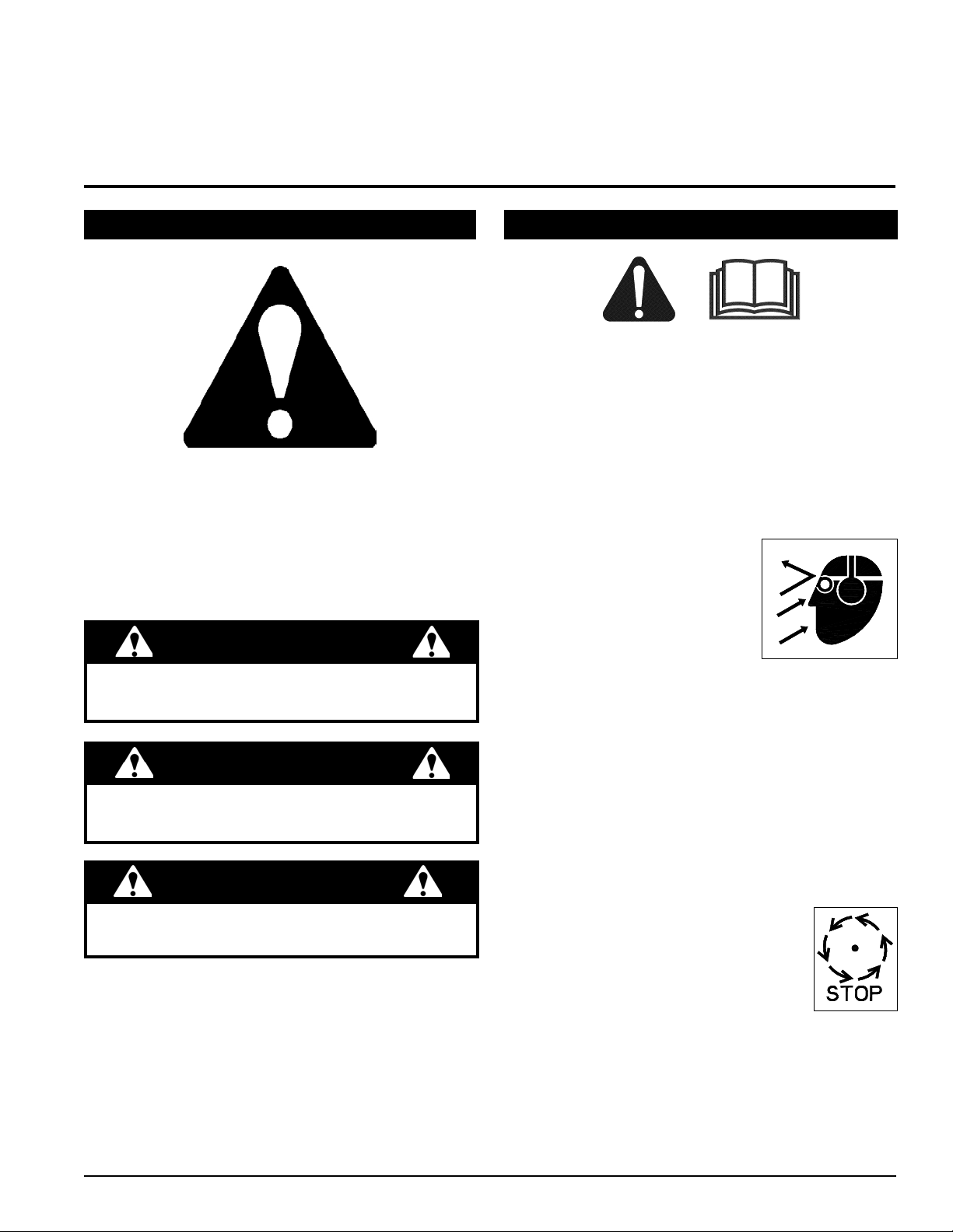
1.1 SAFETY ALERT SYMBOL
The Owner/Operator's manual uses this symbol to alert
you of potential hazards. Whenever you see this symbol,
read and obey the safety message that follows it. Failure
to obey the safety message could result in personal injury,
death or property damage.
CAUTION
Indicates a potentially hazardous situation that, if not
avoided, may result in minor or moderate injury.
WARNING
Indicates a potentially hazardous situation that, if not
avoided, could result in death or serious injury.
DANGER
Indicates an imminently hazardous situation that, if not
avoided, will result in death or serious injury.
1.2 BEFORE OPERATING
Read and understand this Owner/Operator's manual. 1.
Be completely familiar with the controls and the proper
use of this equipment.
Familiarize yourself with all of the safety and operating 2.
decals on this equipment and on any of its attachments
or accessories.
Keep safety decals clean and legible. Replace missing 3.
or illegible safety decals.
Obtain and wear safety glasses and use hearing pro-4.
tection at all times when operating this machine.
Avoid wearing loose fitted cloth-5.
ing. Never operate this machine
wearing clothing with drawstrings that could wrap around
or get caught in the machine.
Do not operate this machine if 6.
you are under the influence of alcohol, medications,
or substances that can affect your vision, balance or
judgement. Do not operate if tired or ill. You must be
in good health to operate this machine safely.
Do not operate this equipment in the vicinity of bystand-7.
ers. Keep the area of operation clear of all persons,
particularly small children. It is recommended that
bystanders keep at least 50 feet (15 meters) away
from the area of operation.
Do not allow children to operate this equipment.8.
Use only in daylight or good artificial light.9.
Do not run this equipment in an 10.
enclosed area. Engine exhaust contains carbon monoxide gas, a deadly
poison that is odorless, colorless and
tasteless. Do not operate this equipment in or near buildings, windows or
air conditioners.
Always use an approved fuel container. Do not remove 11.
fuel cap or add fuel when engine is running. Add fuel
to a cool engine only.
Do not fill fuel tank indoors. Keep open flames, sparks, 12.
smoking materials and other sources of combustion
away from fuel.
9 INCH CHIPPER
1
Page 6
SAFETY
WRONG
WRONG
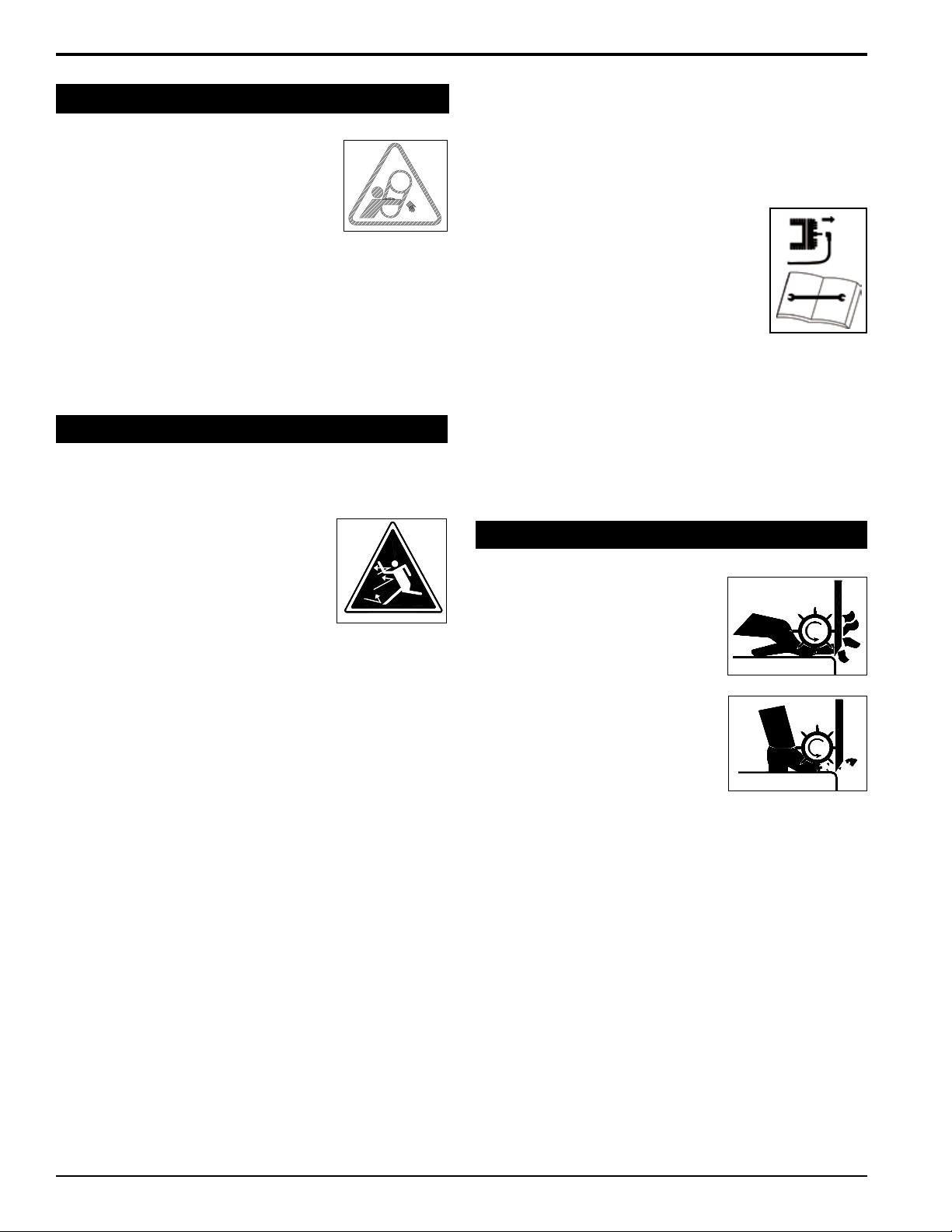
1.2 BEFORE OPERATING (CONT.)
Keep all guards, deflecto rs , and 13.
shields in good working condition.
Before inspecting or servicing any part 14.
of this machine, shut off the machine,
remove the ignition key and make sure
all moving parts have come to a complete stop.
Check that all screws, nuts, bolts, and other fasteners 15.
are secured, tightened and in proper working condition
before starting the machine and once every 8 hours
of operation.
Do not transport or move machine while the machine 16.
is operating or running.
1.3 OPERATION SAFETY
Always stand clear of discharge area when operating 1.
this machine. Keep face and body away from feed
and discharge openings.
Keep hands and feet out of feed and 2.
discharge openings while machine is
operating to avoid serious personal
injury. Stop and allow machine to
come to a complete stop before
clearing obstructions.
Set up your work site so you are not endangering traffic 3.
and the public. Take great care to provide adequate
warnings.
Do not climb on machine when operating. Keep proper 4.
balance and footing at all times.
Check cutting chamber to verify it is empty before 5.
starting the machine.
The disk will continue to rotate when belt is disen-6.
gaged.
Do not insert branches larger than 9 inches in diameter 7.
into chipper or machine damage may occur.
When feeding material into machine, do not allow 8.
metal, rocks, bottles, cans or any other foreign material
to be fed into the machine.
Ensure debris does not blow into traffic, parked cars, 9.
or pedestrians.
Keep the machine clear of debris and other accumu-10.
lations.
Do not allow processed material to build up in the 11.
discharge area. This may prevent proper discharge
and can result in kickback of material through the feed
opening.
Shut off machine immediately if the machine becomes 12.
clogged, the cutting mechanism strikes any foreign
object, or the machine starts vibrating or making an
unusual noise. Shut off the machine, disconnect the
battery, remove the ignition key and make sure all
moving parts have come to a complete stop. After
machine stops:
Inspect for damage.A.
Replace or repair any damaged B.
parts.
Check for and tighten any loose C.
parts.
Disconnect cables from battery and 13.
remove key before doing any inspection or service.
Check blade bolts for proper torque after every 8 hours 14.
of operation. Check blades and rotate or resharpen
daily or as required to keep blades sharp. Failure to do
so may cause poor performance, damage or personal
injury and will void the machine warranty.
1.4 FEED ROLLER SAFETY
The feed ro lle r can cau se 1.
serious injury or death. Keep
hands, feet and clothing away
from the feed roller and chipper
disk blades.
Never climb onto the feed chute 2.
when the unit is operating or
running.
Do not overreach. Keep prop-3.
er balance and footing at all
times.
Never allow passengers to ride 4.
on the feed chute.
When feeding material into the feed roller:5.
Wear eye, face and hearing protection.A.
Release material and stand to side of feed B.
chute.
When inspecting or servicing the feed roller, secure 6.
the feed roller in the raised position using the snap pin
located on the roller slide.
2
9 INCH CHIPPER
Page 7
SAFETY
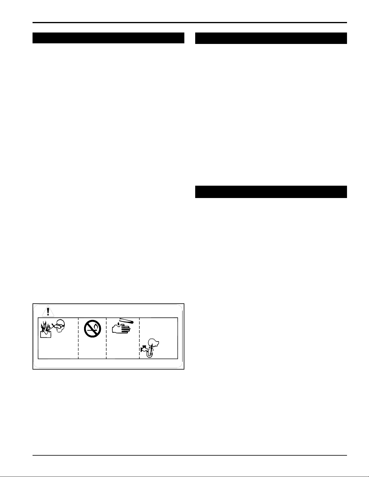
DANGER / POISON
SHIELD EYES
EXPLOSIVE GASES
CAN CAUSE
BLINDNESS OR
INJURY
NO
• SPARKS
• FLAMES
• SMOKING
SULFURIC
ACID
CAN CAUSE
BLINDNESS OR
SEVERE BURNS
FLUSH EYES
IMMEDIATELY
WITH WATER
GET
MEDICAL
HELP
FAST
KEEP OUT OF THE REACH OF CHILDREN. DO NOT TIP. KEEP VENT CAPS TIGHT AND LEVEL.
1.5 BATTERY SAFETY
Improper use and care of the battery on electric start 1.
models can result in serious personal injury or property damage. Always observe the following safety
precautions.
Poison/Danger - Causes Severe Burns. The battery 2.
contains sulfuric acid. Avoid contact with skin, eyes
or clothing. Keep out of reach of children.
ANTIDOTE-External Contact: Flush immediately
with lots of water.
ANTIDOTE-Internal: Drink large quantities of water
or milk. Follow with milk of magnesia, beaten egg
or vegetable oil. Call a physician immediately.
ANTIDOTE-Eye Contact: Flush with water for 15
minutes. Get prompt medical attention.
The battery produces explosive gases. Keep sparks, 3.
flame or cigarettes away. Ventilate area when charging battery. Always wear safety goggles when working
near battery.
The battery contains toxic materials. Do not damage 4.
battery case. If case is broken or damaged, avoid
contact with battery contents.
Neutralize acid spills with a baking soda and water 5.
solution. Properly dispose of a damaged or worn-out
battery. Check with local authorities for proper disposal
methods.
Do not short circuit battery. Severe fumes and fire 6.
can result.
Before working with electrical wires or components, 7.
disconnect battery ground (negative) cable first. Disconnect positive cable second. Reverse this order
when reconnecting battery cables.
1.6 MAINTENANCE/STORAGE SAFETY
Before inspecting, servicing, storing, or changing an 1.
accessory, shut off the machine, disconnect the battery, remove the ignition key and make sure all moving
parts have come to a complete stop.
Replace any missing or unreadable safety decals. Re-2.
fer to the parts manual for part numbers when ordering
safety decals from your chipper dealer.
Allow machine to cool before storing in an enclosure.3.
Store the machine out of reach of children and where 4.
fuel vapors will not reach an open flame or spark.
Never store this machine with fuel in the fuel tank 5.
inside a building where fumes may be ignited by an
open flame or spark. Ignition sources can be hot water
and space heaters, furnaces, clothes dryers, stoves,
electric motors, etc.
1.7 TOWING SAFETY
Rotate the discharge tube to face the opposite direction 1.
of the towing vehicle before towing.
Connect hitch safety chains. Make sure trailer hitch 2.
bolts are tight and secure. Do not attempt to attach
the pintle hitch to a ball type vehicle hitch.
Do not exceed maximum towing speed of 55 miles 3.
per hour. Inflate tires to manufacturer's specifications,
as stated on the tire sidewall. Check wheel lug bolts
periodically to make sure they are secure.
Make sure the jack stand and the rear stabilizer on 4.
trailer are in the UP position to clear the ground during
towing. Place the jack stand on a level surface and
secure it in the DOWN position before use.
Never allow passengers to ride on the chipper.5.
9 INCH CHIPPER
3
Page 8
SAFETY
4*
3
1
2
7
8
9
5
8
6
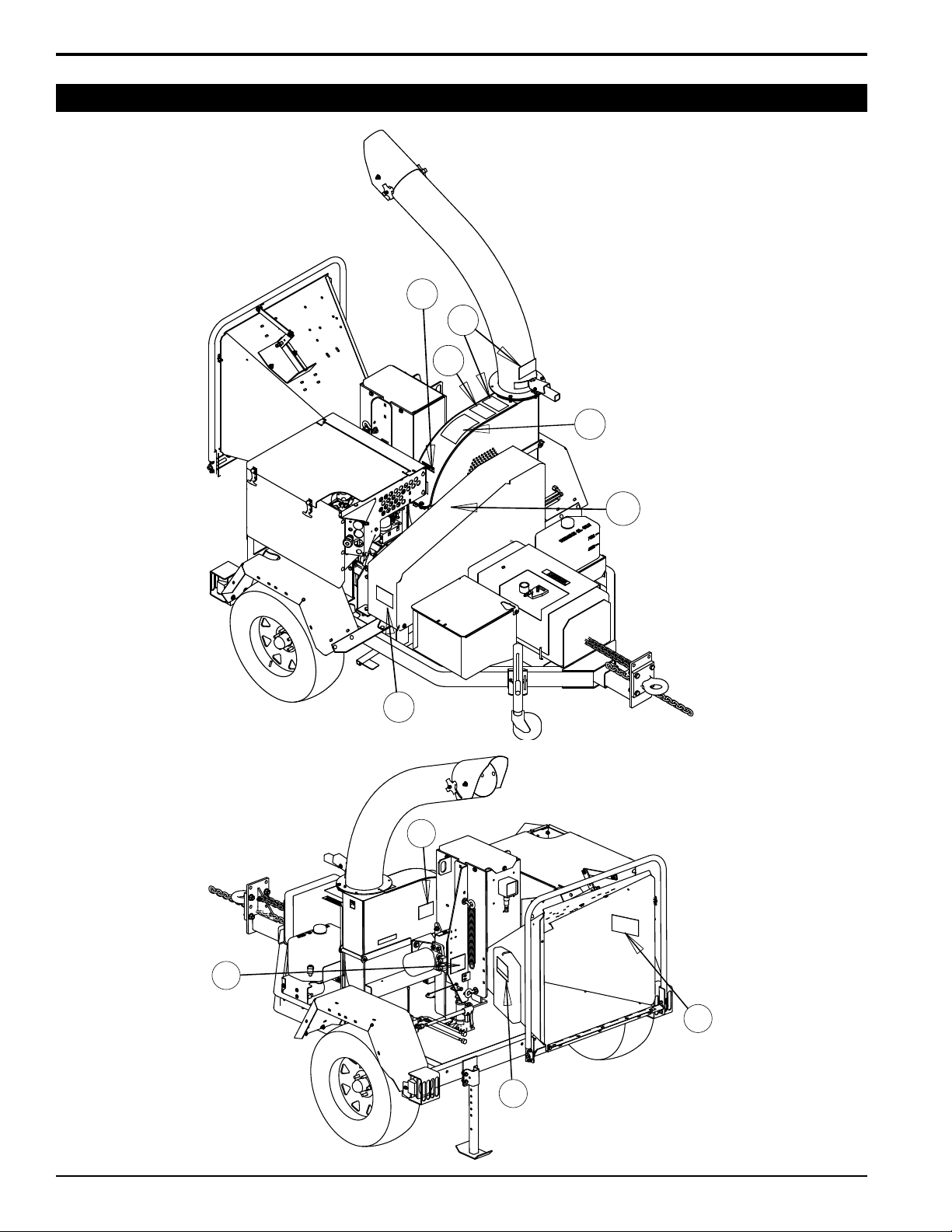
1.8 SAFETY DECAL LOCATIONS
4
9 INCH CHIPPER
Page 9
SAFETY
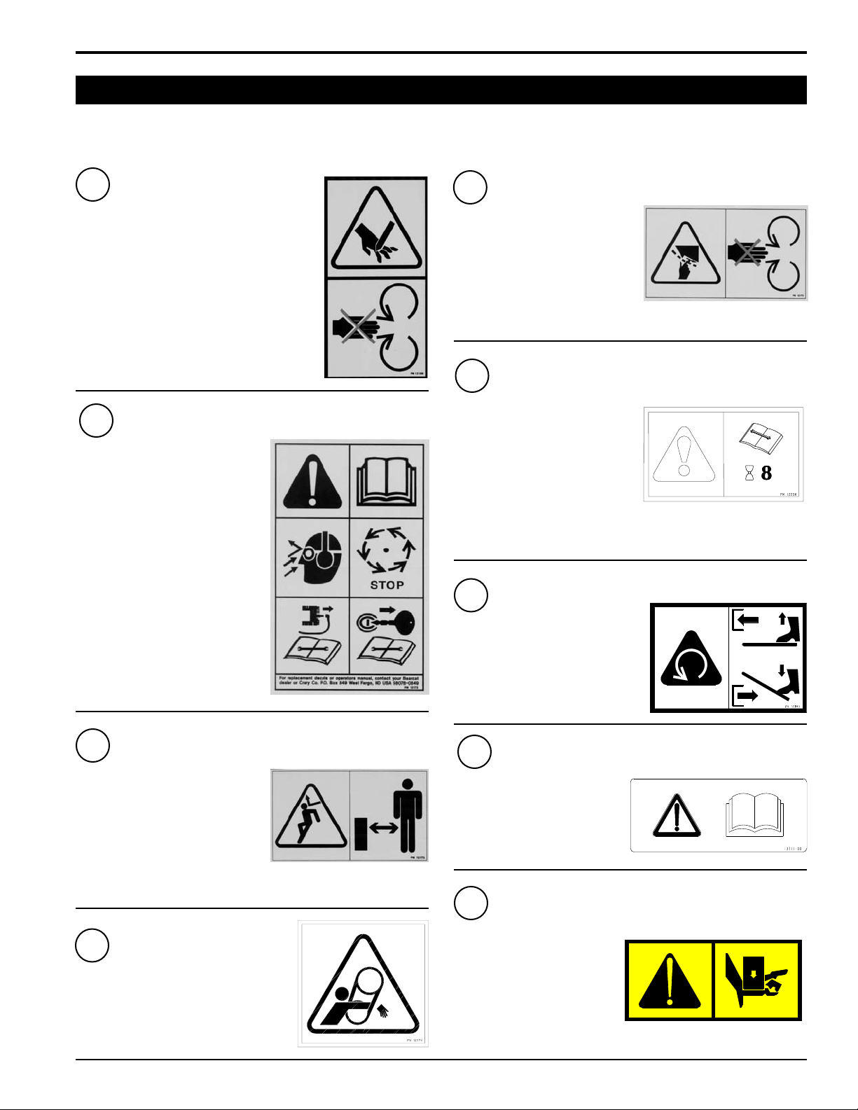
1.9 SAFETY DECALS
Safety and instruction decals are located on the chipper frame and engine. Replace any decal that is damaged or unreadable.
1
KEEP HANDS AND FEET OUT OF INLET AND
DISCHARGE OPENINGS WHILE MACHINE
IS OPERATING TO AVOID SERIOUS PERSONAL INJURY. ALLOW MACHINE TO COME
TO A COMPLETE STOP BEFORE CLEARING
OBSTRUCTIONS.
2
READ AND UNDERSTAND THIS
OWNER/OPERATORS MANUAL.
BE COMPLETELY FAMILIAR WITH
THE CONTROLS AND THE PROPER USE OF THIS EQUIPMENT
OBTAIN AND WEAR SAFETY
GLASSES AND USE HEARING
PROTECTION AT ALL TIMES
WHEN OPERATING THIS MACHINE.
BEFORE INSPECTING OR SERVICING ANY PART OF THIS
MACHINE, SHUT OFF POWER
SOURCE AND MAKE SURE ALL
MOVING PARTS HAVE COME TO
A COMPLETE STOP.
PN 12169
PN 12172
5
KEEP HANDS AND FEET OUT
OF INLET AND DISCHARGE
OPENINGS WHILE MACHINE IS
OPERATING TO AVOID SERIOUS PERSONAL INJURY. ALLOW MACHINE TO COME TO
A COMPLETE STOP BEFORE
CLEARING OBSTRUCTIONS.
6
CHECK BLADE BOLTS FOR
PROPER TORQUE AFTER EVERY 8 HOURS OF OPERATION.
CHECK BLADES AND ROTATE
OR RESHARPEN DAILY OR AS
REQUIRED TO KEEP BLADES
SHARP. REFER TO OWNERS
MANUAL FOR INSTRUCTIONS.
FAILURE TO DO SO MAY CAUSE POOR PERFORMANCE, DAMAGE OR PERSONAL INJURY AND WILL VOID THE MACHINE
WARRANTY.
7
PRESS CLUTCH PEDAL DOWN
WITH FOOT TO DISENGAGE BELT
WHILE STARTING ENGINE. SLOWLY RELEASE FOOT TO ENGAGE
CHIPPER BELT AFTER CHIPPER
IS RUNNING.
PN 12175
PN 12250
PN 12183
3
DO NOT OPERATE THIS EQUIPMENT IN THE VICINITY OF BYSTANDERS. DO NOT ALLOW
CHILDREN TO OPERATE THIS
EQUIPMENT. ALWAYS STAND
CLEAR OF DISCHARGE AREA
WHEN OPERATING THIS MACHINE. KEEP FACE AND BODY
AWAY FROM DISCHARGE AREAS.
4
DO NOT OPERATE MACHINE WITHOUT SHIELDS IN PLACE. FAILURE TO
DO SO MAY CAUSE SERIOUS INJURY
OR DEATH.
PN 12173
PN 12174
8
READ AND UNDERSTAND THIS
OWNER/OPERATORS MANUAL.
BE COMPLETELY FAMILIAR
WITH THE CONTROLS AND THE
PROPER USE OF THIS
EQUIPMENT.
9
FEED ROLLER SUPPORT MUST
BE SECURED IN THE UP POSITION PRIOR TO SERVICING
CHIPPER FEED AREA. FEED
ROLLER CAN FALL AND CAUSE
SEVERE BODILY HARM. CONSULT OWNERS MANUAL FOR
PROPER METHOD OF SECURING FEED ROLLER SUPPORT.
LOWER FEED ROLLER BEFORE OPERATING CHIPPER.
9 INCH CHIPPER
PN 13711-00
PN 18983-00
5
Page 10
2
SAFETY
CHAIN
3/8” x 2-1/2”
BOLT
3/8”
WASHER
5/8” x 4-1/2”
BOLT
PINTLE
RING
5/8” CENTERLOCK
NUTS
5/8”
WASHERS
3/8”
WASHER
3/8”
NYLOCK
NUT
LYNCH
PIN
TOP LINK
PIN
ASSEMBLY
Section
NOTE
Axle and hitch assemblies for "S" models are supplied
by the distributor and may vary from the illustrations
shown below.
2.1 ATTACH TRAILER WHEELS
Remove the chipper from its shipping crate. Place the 1.
unit on a level surface before attempting to assemble
it.
Raise the trailer several inches from the ground with a 2.
hoist or jack. Support the chipper securely.
Lift one wheel to a hub and align the wheel lug holes 3.
with the hub lug bolts. Thread the lug nuts onto the
bolts and tighten them to 75 ft-lbs. Follow a star pattern
when tightening the lug bolts. Repeat this step for the
remaining wheel.
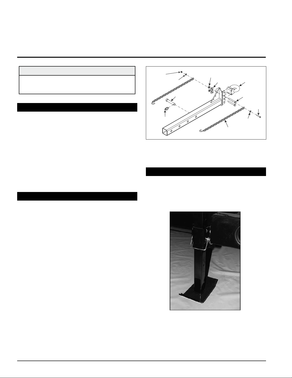
Figure 2.1, Trailer hitch assembly
2.3 ATTACH REAR STABILIZER
2.2 ATTACH PINTLE HITCH
Insert the adjustable hitch into the hitch opening in the 1.
chipper trailer.
Attach the pintle hitch ring to the adjustable hitch with 2.
two 5/8" x 4-1/2" bolts, washers, and centerlock nuts.
Torque the bolts to 160 ft-lbs.
Connect the safety chains to the adjustable hitch 3.
weldment as shown in Figure 2.1. Use a 3/8" x 2-1/2"
bolt, two washers, and a nylock nut to attach the safety
chains.
Push the top link pin through the holes in the hitch and 4.
trailer. Secure the top link pin with a lynch pin.
Adjust the ring on the pintle hitch to make the chipper
trailer as level as possible when connected to the towing
vehicle.
The rear stabilizer (Figure 2.2) is installed by sliding the
stabilizer into the trailer support guide on the rear of the
chipper frame. The stabilizer is secured and adjusted with
the provided snap pin.
Figure 2.2, Rear stabilizer
6
9 INCH CHIPPER
Page 11

CHIPPER
CHUTE
HYDRAULIC
FEED
2.4 ATTACH CHUTE SUPPORT
CHUTE SUPPORT
WELDMENT
3/8” x 2”
BOLT
EXTENSION
TRAY LIP
CHIPPER CHUTE LIP
EXTENSION
HINGE
Attach the chute support to the rear end of the trailer 1.
using one 3/8" x 2" bolt, washer and locknut. Torque
to 35 ft-lbs. Refer to Figure 2.3 for proper positioning
of the weldment.
Figure 2.3, Attaching the chute support
2.5 ATTACH CHIPPER CHUTE
ASSEMBLY
Figure 2.4, Chipper chute assembly
2.6 ATTACH EXTENSION TRAY
Tilt the extension tray up, so the bottom of the tray is 1.
facing outward (Figure 2.5). Slide the extension tray lips
between the extension hinge and chipper chute lips.
Tilt the extension tray down until the tray rests on the 2.
extension hinge, and the extension tray lips contact
the back of the chipper chute lips.
Insert five 3/8" x 1" carriage bolts (included in owner's 3.
kit) through the extension tray and hinge. Secure the
bolts with washers and nylock nuts from the bottom.
Attach the chute support weldment to the middle hole 4.
of the chipper chute by using the existing bolt.
Do not operate this unit without the chipper chute
correctly installed. Rotating cutting blades can cause
serious personal injury.
Use a support or hoist to hold the chipper chute in 1.
place on the hydraulic feed (Figure 2.4).
Attach the chipper chute to the hydraulic feed using 2.
eight 3/8" x 1-1/2" carriage bolts and nylock nuts. Use
three bolts on each side and two on the bottom. To insert the top bolts, rotate the feed roller until the cut-out
in the side of the drum matches the bolt holes.
WARNING
Figure 2.5, Attaching the extension tray
9 INCH CHIPPER
7
Page 12

ASSEMBLY
BLOWER
DISCHARGE
TUBE
MOUNTING FLANGE
SPACER
DISCHARGE CLAMP
LOCK LEVER
INSERT CABLE
THROUGH HOLE
NUT
CLEVIS
ASSEMBLY
DETENT
BALL
CONTROL
ARM
CABLE ANCHOR
WELDMENT
HYDROSTAT
CONTROL
CABLE
FEED
CONTROL
LEVER
2.7 CONNECT CONTROL CABLE
Remove the clevis assembly from the hydrostatic 1.
control cable end (see Figure 2.6). Remove one nut
on the cable end. Insert the cable end into the hole
in the cable anchor weldment. Replace the nut and
clevis assembly.
Attach the clevis assembly to the center hole on the 2.
feed control lever.
Adjust the cable detent ball to contact the detents in 3.
the cable anchor weldment when the control arm is in
the forward or reverse position.
IMPORTANT
See Section 3 for hydrostatic pump start-up procedure.
2.8 ATTACH DISCHARGE TUBE
Attach the blower discharge tube to the chipper frame 1.
mounting flange. Slide the discharge tube clamp underneath the mounting flange (Figure 2.7).
Install the second half of the spacer and clamp (in-2.
cluded in owner's kit) to the tube and flange with 3/8"
x 1-1/4" bolts and nuts. Rotate the tube 360 degrees
to make sure it is mounted correctly. Lock it in place
with the lock pin.
Figure 2.6, Control cable components
Figure 2.7, Attaching the discharge tube
2.9 INSTALL THE BATTERY
The chipper is not shipped with a battery. Use group 1.
22F 300 CCA minimum.
Mount the battery in the battery box located next to 2.
the fuel tank. Connect the positive battery cable to
the positive terminal and the negative cable to the
negative terminal.
IMPORTANT
If any bolts or nuts are dropped in the machine, be
sure to remove them before starting the machine.
8
9 INCH CHIPPER
Page 13

2.10 CHECKING/ADDING FLUIDS
2.10.1 DIESEL FUEL
For best results, use only fresh, clean #2 diesel fuel. An
additive for cold weather may be used to prevent fuel from
turning to a gel.
To add fuel:
Stop engine and wait for all moving parts to come to 1.
a complete stop. Allow the engine and muffler to cool
for at least three minutes.
Clean area around fuel fill cap and remove cap.2.
Using a clean funnel, fill fuel tank to 1/2" below bottom 3.
of filler neck to allow room for expansion.
Replace fuel cap and wipe up any spilled diesel fuel.4.
2.10.2 MOTOR OIL
The machine was shipped with oil in the engine, as it 1.
was tested at the factory.
To determine which type of oil to use, refer to the 2.
engine owner's manual included in the owner's kit of
the chipper.
Remove the oil fill plug.3.
Checking as necessary, add oil to the motor until the 4.
dipstick shows the correct reading. Replace oil fill
plug.
ASSEMBLY
2.10.3 ENGINE COOLANT
You may need to add coolant before you start the diesel
engine. While operating, make sure the uid is between the
full and the low marks. Add if necessary. Refer to Kubota
engine manual for further coolant information.
2.10.4 HYDRAULIC FLUID
The hydraulic fluid tank is located next to the chipper
frame. Premium hydraulic fluids containing high quality rust,
oxidation and foam inhibitors are required. These include
premium turbine oils, API CD engine oils per SAE J183,
M2C33F or G automatic transmission fluids meeting Allison
C-3 or Caterpillar TO-2, and certain specialty agricultural
tractor fluids. See Section 3 for hydrostatic pump start-up
procedure.
9 INCH CHIPPER
9
Page 14

3
3
10
2
1
9
8
7
6
5
4
11
Section
3.1 CONTROLS
OPERATION
Chipper Chute:1. Feeds materials to the chipper blades
for chipping.
Discharge Tube: 2. Chipped material exits through this
tube. It is adjustable 360 degrees.
Rotor Access Cover: 3. Tilts up to expose rotor.
Drive Belt Shield:4. Never remove shields when in
use.
Fuel Tank:5. Fuel level indicator is located on top.
Pintle Hitch: 6. Always use safety chains when towing.
Pivoting Tongue Jack:7. Always have in UP position
and clear from ground when moving. When in use,
place in DOWN position on a level surface. Turn handle
to raise or lower wheel.
Battery Box: 8. Use group 22F 300 CCA min.
Belt Engagement Pedal:9. Used to disengage rotor
assembly drive belt.
Control Panel: 10. Contains the key switch, throttle control, Murphy switch and gauges.
CAUTION
Wear safety glasses at all times when operating the
machine. Do not wear loose tting clothing. The operator should always wear heavy boots, gloves, pants
and shirt. Use common sense and practice safety to
protect yourself from branches, sharp objects and
other harmful objects.
NOTE
The heavy rotor will continue to turn for some time
after the engine has been shut off. You can tell that the
rotor has stopped when no noise or machine vibration
is present. Inserting a branch into the chipper chute
to contact the blades will slow the rotor and shorten
stopping time.
10
Figure 3.1, 9 inch chipper controls
9 INCH CHIPPER
Page 15

3.2 OPERATION
Glow Plug
Indicator
No Charge
Indicator
Throttle
Murphy
Switch
Hour Meter
(Optional)
Temperature
Gauge
Key Switch
Pressure
Gauge
CONTROLS AND OPERATION
CAUTION
Move machine to a clear, level area outdoors before
starting. Do not operate machine on a paved, concrete
or gravel surface. Do not operate in the vicinity of
bystanders. Make sure cutting chamber is empty before
starting.
3.2.1 STARTING
Before starting, fill engine with oil to the correct level. 1.
Some oil usage is normal, so check the level before
each use. See engine manual for additional starting,
operation and maintenance instructions.
WARNING
Handle fuel with care. It is highly flammable. Always use
an approved container and fill tank outdoors. Never add
fuel to a running or hot engine.
Fill fuel tank with fresh, clean diesel fuel. For instruc-2.
tions on bleeding the fuel system on initial start up or
if fuel runs out, see engine manual.
Turn key switch to preheat position. Hold in preheat 3.
position for several seconds until glow plug indicator
light (Figure 3.2) switches off.
Push throttle control in until it stops.4.
Depress belt engagement pedal, which allows engine 5.
to start. See the operation/start-up decal by the belt
engagement pedal before starting.
Push in and hold Murphy switch push-button. Continue 6.
to hold Murphy switch until engine is running.
Activate the starter switch. Release the switch as soon 7.
as the engine starts. Do not crank for more than 10 seconds. Release Murphy switch after engine is running.
Hold Murphy switch in longer if engine immediately
stalls after releasing.
3.2.2 STOPPING
Gradually move throttle to slowest position.1.
Disengage drive belt.2.
Turn key switch to off position.3.
Allow machine to come to a complete stop. Release 4.
the belt engagement pedal to help slow the rotor once
the engine has stopped running.
NOTE
The heavy rotor will continue to turn for some time
after the engine has been shut off. You can tell that the
rotor has stopped when no noise or machine vibration
is present. Inserting a branch into the chipper chute
to contact the blades will slow the rotor and shorten
stopping time.
NOTE
The Murphy switch system will shut the engine off if
the oil pressure is too low or if the engine temperature
is too high. If the engine will not run or shuts off for
these reasons, consult your local dealer.
Push center throttle control button in. Increase throttle 8.
control to full. Turn throttle control knob clockwise to
achieve maximum RPM,
Slowly release belt engagement pedal. This will en-9.
gage the drive belt, and the rotor will turn. If the engine
stalls when engaging the drive belt, release the pedal
more slowly.
9 INCH CHIPPER
Figure 3.2, Chipper control panel
11
Page 16

CONTROLS AND OPERATION
3.2 OPERATION (CONT.)
WARNING
Please read and follow all safety instructions in this
manual. Failure to operate the chipper in accordance
with the safety instructions MAY RESULT IN PERSONAL
INJURY!
3.2.3 CHIPPING
This chipper is designed to chip a variety of materials into
a more readily decomposing or handled condition. The
following guidelines can be used to help you get started.
Be sure the unit is at full operating speed before you 1.
start to chip material.
Select limbs that are up to 9 inches in diameter. Trim 2.
side branches that cannot be bent enough to feed into
the chipper chute. Small diameter branches can be
held together in a bundle and fed in simultaneously.
Feed brush from the side of the chute, rather than 3.
from the front. Then, step aside to avoid being hit by
the brush moving into the chipper.
Never lean over the chute to push objects into the cut-4.
ting device. Use a push stick or brush paddle.
WARNING
Keep face and body away from the feed opening. Do
not over reach. Keep proper balance and footing at all
times.
Never use shovels or forks to push brush. They can 5.
go through the chipper, are expensive to replace, and
cause major damage. In addition, metal pieces can
be shot back like shrapnel to injure or kill the operator
or bystanders.
Never push brush into the chute with your feet.6.
Engage the hydraulic feed by moving the control arm. 7.
Pull the arm toward you to engage the hydraulic feed.
In the forward direction, the feed rate increases as the
arm is moved.
Place branch, butt end first, into the chipper chute until 8.
it contacts the hydraulic feed roller and is drawn into
the chipper blades. The actual feed rate of the branch
into the chipper will depend on the type of material fed
and the sharpness of the cutting blades.
If the engine slows to where it may stall, push the con-9.
trol lever inwards to slow or stop the material feeding
and allow engine to recover. Pull the lever out to restart
feeding when the engine is back to full speed.
If the chipper jams, reverse the feed by pushing the 10.
control arm to reverse direction. Remove the branch
and rotate it before reinserting it into the chute. Alternately insert and retract the limb or insert continuously
at a rate that will not stall the engine.
Chipping dead, dry material will create heat and dull the 11.
chipping blades quickly. Alternate greener material with
dry material to lubricate the chipping blades for longer
life and better performance. When the chipping blades
become dull, they will require sharpening. Refer to the
Service and Maintenance section for more information
on sharpening blades.
WARNING
Do not leave machine unattended. Do not inspect or
service the machine unless the engine is stopped.
3.3 HYDRAULIC FEED OPERATION
3.3.1 FLUIDS
Premium hydraulic fluids containing high quality rust,
oxidation and foam inhibitors are required. These include
premium turbine oils, API CD engine oils per SAE J183,
M2C33F or G automatic transmission fluids meeting Allison
C-3 or Caterpillar TO-2, and certain specialty agricultural
tractor fluids.
CAUTION
Handle pressurized hydraulic fluid carefully. Escaping
pressurized hydraulic fluid can have sufficient force to
penetrate your skin causing serious injury. This fluid
may also be hot enough to burn. Serious infection or
reactions can develop if proper medical treatment is not
administered immediately.
3.3.2 HYDROSTATIC PUMP START UP
Follow this start-up procedure when starting a new
installation or when restarting an installation in which the
hydrostatic pump has been removed from the system.
1. Before starting the hydrostatic pump, make sure all system components (reservoir, fittings, etc.) are clean.
2. Fill the reservoir with recommended hydraulic fluid,
which should be filtered before entering the reservoir.
3. The inlet line leading from the reservoir to the charge
pump must be filled before start-up. Loosen the fitting
on this inlet line until oil bleeds out.
12
4. Start the engine and run at the lowest possible RPM.
9 INCH CHIPPER
Page 17

Feed Control
Lever
Forward
Reverse
Neutral
3.3 HYDRAULIC FEED OPERATION (CONT).
WARNING
Do not start engine unless pump is in neutral or detent
position on the cable.
5. As air is purged from the unit, the oil level in the reservoir will drop and bubbles may appear in the fluid.
Refill the reservoir as necessary.
6. Run the unit in both directions for several minutes until
any remaining air is purged from the unit. Refill the
reservoir as necessary.
7. Check to make sure the feed roller stops when the
control arm is in the neutral position. Adjust the cable
clevis or anchor if the feed roller doesn't stop.
CONTROLS AND OPERATION
Figure 3.4, Control arm operation
3.5 SAFETY BAR ("S" MODELS)
8. Shut down the engine, check for and correct any
fluid leaks, and check the reservoir level. Add fluid
if necessary. The hydrostatic pump is now ready for
operation.
Figure 3.3, Hydrostatic pump components
3.4 CONTROL ARM OPERATION
1. Start the chipper engine. Bring the chipper up to operating speed.
3.5.1 RESETTING THE CHIPPER
The safety bar (See Figure 3.5) located along the chute
extension tray will stop the chipper when pushed in. The
reset button for this bar sits on top of the chipper chute.
When the safety bar has been activated, a red light will
come on signaling that the operator reset button will need
to be pushed before the feed roller will function. If false
trips occur, the reset button can be held in to override the
system. Upon start-up, the safety bar light will be on and
will need to be reset before the feed roller will operate.
3.5.2 LOCKING IN TRAVEL POSITION
The safety bar will lock into travel position. Place the
extension tray in an upright position. Pushing the safety bar
down will lock the bar. To unlock, lower the extension tray
and push in on the safety bar. This will release the flange
and allow the safety bar to move freely.
2. Engage the hydraulic feed by moving the control arm
as shown in Figure 3.4. In the forward direction, the
feed rate increases as the arm is moved.
3. Feed the branch (up to nine inches in diameter).
4. If the chipper jams, reverse the feed by moving the
control arm in the reverse direction. Remove the branch
and rotate it before inserting it into the chute again.
9 INCH CHIPPER
Figure 3.5, Safety bar components ("S" models)
13
Page 18

CONTROLS AND OPERATION
3.6 ELECTRONIC FEED SENSOR
The LOFA control connects to the shaft sensor and solenoid
coil. The sensor (Figure 3.6) should be positioned 1/32"
from the rotor collar bolt. The solenoid coil is attached to
the crossover relief valve (Figure 3.7).
When the system senses that the rotor RPM has dropped
below a certain preset level, it will slow the hydraulic feed.
When the rotor RPM returns to a normal operating level,
the hydraulic feed will return to its previous rate.
Figure 3.6, Proximity sensor
Figure 3.7, Crossover relief valve
14
9 INCH CHIPPER
Page 19

3.7 LOFA CONTROL PROGRAMMING
CONTROLS AND OPERATION
STEP 1. INITIATING PROGRAM MODE
Hold down the “S” button while turning the engine key
to the “on” position until “L” starts to flash on the LCD
(Figure 3.8).
STEP 2. ENTER LOW (L = LOW) RPM
The low setting is the RPM speed where the feed roller
stops. The “up” arrow increases the RPM setting, while
the “down” arrow decreases the RPM setting. Setting the
speed lower causes the engine to lug down more before
the feed roller stops.
Hold the appropriate (either up or down) arrow until 1.
the desired RPM speed is displayed (Recommended
1375 rpm).
Push the “S” button once with the desired RPM setting 2.
displayed to save. Do not choose a setting equal to
or below zero.
STEP 3. ENTER NORMAL
(N = NORMAL) RPM
The normal setting is the RPM speed that the chipper rotor
usually rotates
Hold the appropriate (either up or down) arrow until 1.
the desired RPM speed is displayed (Recommended
1500 rpm).
Push the “S” button once with the desired RPM setting 2.
displayed to save.
STEP 6. ENTER NUMBER OF POLES
(IPU=NUMBER OF POLES)
The number of poles is used to indicate the number of
speed pickup devices.
Hold the appropriate (either up or down) arrow until 1.
(1) is displayed.
Push the "S" button once with one (1) displayed to 2.
save.
NOTE
When approaching the end of a log, it may be necessary
to manually override the automatic feed sensor. Be sure
to pay attention to the engine speed and feeding of
the material.
STEP 4. ENTER HIGH (H = HIGH) RPM
The high setting is not needed with this application.
Set to zero to deactivate.1.
Push the “S” button once with zero displayed to 2.
save.
STEP 5. ENTER RETURN
(RET = RETURN) RPM
The return setting is the RPM speed where the feed roller
restarts. The feed roller should restart before the rotor
reaches “normal” RPM to maximize chipper efficiency.
Setting the speed higher allows the engine to recover more
before the feed roller restarts.
Hold the appropriate (either up or down) arrow until 1.
the desired RPM speed is displayed (Recommended
1400 rpm).
Figure 3.8, LOFA control
9 INCH CHIPPER
15
Page 20

4
Section
SERVICE & MAINTENANCE
4.1 MAINTENANCE SCHEDULE
The items in the service and maintenance schedule are
to be checked, and if necessary, corrective action taken.
This schedule is designed for units operating under normal conditions. If the unit is operating in adverse or severe usage conditions, it may be necessary for the items
to be checked and serviced more frequently. See the engine owners manual for further engine maintenance and
troubleshooting problems.
SERVICE AND MAINTENANCE SCHEDULE
REFER TO
COMPONENT
AIR CLEANER CHECK AND CLEAN (1)
AIR INTAKE CLEAN (1)
ENGINE OIL AND OIL
FILTER
FUEL FILTER REPLACE
WATER LEVEL CHECK
ENGINE OIL CHECK
MAINTENANCE
REQUIRED
CHANGE (1)
ENGINE
OPERATOR
MANUAL
WARNING
To prevent personal injury or property damage, shut
off engine and make sure all moving parts have
come to a complete stop before servicing, adjusting
or repairing.
FREQUENCY
EVERY 8
HOURS
EVERY
25
HOURS
EVERY
50
HOURS
EVERY
250
HOURS
EVERY
YEAR
CHIPPER ANVIL
CHIPPER BLADES
ALL INTERNAL AND
EXTERNAL NUTS AND
BOLTS
BELT CONDITION CHECK
BELT TENSION CHECK
GREASE ZERKS LUBE
ENTIRE MACHINE CLEAN
HYD. OIL FILTER REPLACE
WHEEL BEARINGS CHECK AND REPACK
(1) PERFORM MORE FREQUENTLY UNDER EXTREMELY DUSTY CONDITIONS.
(2) PERFORM MORE FREQUENTLY WHEN CHIPPING DRY OR DIRTY WOOD.
As the Chipper Limited Warranty states, failure by the Owner to perform normal maintenance will void the machine's
warranty. The aggressive, high-speed nature of chipping REQUIRES THE OWNER TO PERFORM THE ABOVE LISTED
NORMAL MAINTENANCE. Special consideration to maintain and re-torque the CHIPPER ANVIL, CHIPPER BLADES,
AND ALL INTERNAL AND EXTERNAL NUTS AND BOLTS is the sole responsibility of the Owner. Failure by the Owner
to do so shall be cause for denied warranty.
CHECK 1/16" TO 1/8" CLEARANCE AND RE-TORQUE TO
75 FT- LBS. (2)
CHECK SHARPNESS AND
RE-TORQUE TO 120 FT-
LBS. (2)
RE-TORQUE PER ASSEMBLY
TORQUE CHART
16
9 INCH CHIPPER
Page 21

SERVICE & MAINTENANCE
4.2 REPLACEMENT & MAINTENANCE CHART
Note: When ordering replacement parts, be sure to identify the model and serial number of the machine.
Replacement Parts Ordered
Date Part
Ordered
Date Part
Replaced
Replaced By Checked By
9 INCH CHIPPER
17
Page 22

SERVICE & MAINTENANCE
MOUNTING SURFACE
DO NOT GRIND
MOUNTING SURFACE
SHARPENED
SURFACE
SHARPENED
SURFACE
45°
.38
ROTOR
HOUSING
4.3 SHARPENING CHIPPER BLADES
WARNING
Before inspecting or servicing any part of the machine,
shut off engine and make sure all moving parts have
come to a complete stop. The chipping blades are sharp!
Use care when working on machine to avoid injury.
WARNING
The rotor assembly has a lock mechanism. When working on the rotor assembly, use the lock mechanism at
all times. Remove plastic bearing cover by the chip-
per chute. There is a hole in the rotor jack shaft and
a matching hole in the bracket mounted to the rotor
bearing front side. Install a punch through the rotor
shaft and bracket to lock the rotor in place.
The chipper blades will eventually become dull, making
chipping difficult. It is recommended that the chipper blades
are sharpened every 5-15 hours of chipper operation. To
remove the chipping blades for sharpening:
CHIPPING BLADE SHARPENING TIPS
Poor chipping performance is usually a result of dull
chipping blades. If your chipper's performance has
decreased, check for the following symptoms:
• Severe vibration when feeding material into the chipper.
• Small diameter branches do not self-feed.
• Chips discharge unevenly or have stringy tails–espe-
cially when chipping green branches.
Before you sharpen the chipping blades, check for
permanent damage. Replace the blade if:
• The blade is cracked (especially around the bolt holes) or
the edges are too deeply chipped to be ground smooth.
• The base of the cutting edge is worn or has been re-sharpened so that it is too close to the rotor chipping slot.
4.4 SETTING BLADE CLEARANCE
The four-edged chipping anvil located directly behind the
chipper chute (Figure 4.2) should clear the chipping blades
by 1/16" to 3/16" inch. The chipping anvil is adjustable and
reversible. It is best accessed by using the feed roller jack
to raise the feed roller.
1. Remove the two retaining bolts holding access cover
to main frame assembly.
2. Tilt access cover over to allow rotor access. Rotate
the rotor so that the bolts holding a chipping blade are
most accessible.
3. Remove the two nuts holding the blade itself. Repeat
for all four blades. The four chipping blades have two
edges per blade and can be reversed one time each
before sharpening. If both sides have not been used,
remove and reverse the chipping blades. Reinstall
chipping blades and proceed with chipping.
To grind the angled edge of the chipping blade to 45
degrees (Figure 4.1): Grind the blades on a slow-speed
wet grinder if possible, or have them sharpened by a
professional. If you use a bench grinder, be careful when
grinding so that the blade material does not get too hot
and change color. This will remove the blade's special heat
treated properties. Use short grinding times and cool with
water. Try to remove an equal amount from each blade to
maintain balance. Replace the chipping blades and tighten
bolts to 120 ft-lbs. Close cover and replace bolts.
Figure 4.2, Chipping anvil location
Stop engine and wait for all moving parts to stop.1.
Lift rotor access cover and expose rotor. 2.
Remove the lock pin from storage position (see 3.
Figure 4.3)
Turn check valve clockwise to engage the pump.4.
Pump the handle to raise the feed roller until the lock pin 5.
position aligns with one of the support bracket holes.
18
Figure 4.1, Sharpening the chipper blades
Secure the position by putting the lock pin through the 6.
support bracket and lock pin position.
Accessing the anvil from under the feed roller, loosen the 7.
three 1/2" bolts that hold the chipper anvil to the frame.
If the chipping anvil edge is damaged or worn unevenly, 8.
remove the anvil and use one of the other three edges.
Adjust anvil inward or outward.9.
9 INCH CHIPPER
Page 23

SERVICE & MAINTENANCE
SPAN LENGTH
FORCE
20 LBS
7/16" DEFLECTION
FEED
ROLLER
JACK
CHECK
LOCK PIN
STORAGE
POSITION
SUPPORT
BRACKET
LOCK PIN
POSITION
4.4 SETTING BLADE CLEARANCE (CONT.)
Tighten bolts on anvil to 75 ft-lbs. Make sure all blades 10.
clear the anvil by 1/16" to 3/16".
Remove lock pin and put it back into its storage po-11.
sition. LEAVING THE LOCK PIN IN ANY OTHER
POSITION MAY INTERFERE WITH FEED ROLLER
OPERATION.
Turn the check valve counterclockwise to disengage 12.
the pump and lower the jack.
4.6 REPLACING DRIVE BELT
Check the condition of the drive belt annually or after every
25 hours of operating, whichever comes first. If the belt is
cracked, frayed, or worn, replace it. To replace or adjust
drive belt, proceed as follows:
Shut off engine.1.
Remove large belt guard.2.
Remove the hydraulic pump belt by loosening the bolts 3.
on the hydraulic pump (Figure 4.4).
Take the tension off the drive belt by depressing the 4.
belt engagement pedal. Remove the drive belt from
pulleys.
Figure 4.3, Feed roller jack
4.5 CLEARING PLUGGED ROTOR
WARNING
If the machine becomes plugged, shut off engine and
allow the machine to come to a complete stop before
cleaning debris.
Stop engine and wait for all moving parts to stop.1.
Remove bolts and lift rotor access cover.2.
Remove the lock pin from storage position (see 3.
Figure 4.3)
Turn check valve clockwise to engage the pump.4.
Pump the handle to raise the feed roller until the lock pin 5.
position aligns with one of the support bracket holes.
Secure the position by putting the lock pin through the 6.
support bracket and lock pin position.
Clean the debris out of the feed roller housing. Turn 7.
the rotor by hand to be sure it is free to rotate.
Remove lock pin and put it back into its storage po-8.
sition. LEAVING THE LOCK PIN IN ANY OTHER
POSITION MAY INTERFERE WITH FEED ROLLER
OPERATION.
Turn the check valve counterclockwise to disengage 9.
the pump and lower the jack.
Close rotor access cover and secure with bolts.10.
Depress belt engagement pedal, start engine, and 11.
resume operation.
9 INCH CHIPPER
Figure 4.4, Drive belt
Install the new drive belt on pulleys.5.
Check pulley alignment with a straight edge and adjust 6.
engine if needed.
Check belt tension and adjust if needed. The belt deflec-7.
tion at the center of the belt should be 7/16" when a 20
lb. load is placed against the belt (see Figure 4.5).
Reinstall hydraulic pump belt. Readjust hydraulic pump 8.
belt tension by sliding the hydraulic pump in the mounting slots. Tighten bolts.
Replace belt guard.9.
Depress belt engagement pedal, start engine, engage 10.
drive belt, and test unit. Readjust pulleys and belt tension if needed.
Figure 4.5, Belt tension
19
Page 24

SERVICE & MAINTENANCE
4.7 REPLACING ROTOR BEARINGS
Remove the two retaining bolts holding the access 1.
cover to main frame assembly. Tilt access cover over
to allow rotor access.
Remove large belt guard.2.
Loosen bolts on hydraulic pump and remove hydraulic 3.
pump belt.
Take the tension off the drive belt by depressing the 4.
belt engagement pedal. Then, remove the drive belt
from pulleys. Using the push bolts from the bushing,
remove the bushing and pulley from the rotor shaft.
Remove the four 1/2" bolts on each rotor bearing and 5.
take off the sensor bracket.
Using an overhead hoist or lifting device, lift the rotor 6.
assembly completely out of the frame. The complete
rotor assembly is 275 lbs.
Once the rotor assembly is out of the frame, remove 7.
both collars and bearings. Place new bearings on rotor
shaft. Reinstall front collar onto shaft.
Use the overhead hoist or lifting device to return the 8.
complete rotor assembly to the chipper frame.
Slide rotor back until the front collar is tight against the 9.
front bearing. Attach the front bearing to the frame with
four 1/2" bolts. Tighten bolts to 75 ft-lbs. Check and
adjust chipper anvil if needed. Bolt the rear bearing to
chipper frame. Reattach sensor bracket to rear bearing
using a top bearing bolt.
Slide rear collar on shaft against rear bearing. Make 10.
sure the collar bolt lines up with the sensor. Slide bushing onto shaft with flange against collar and lock bushing to shaft. Attach large pulley to bushing. Replace
drive belts on pulleys.
Check pulley alignment with a straight edge and adjust 11.
engine if needed. Check belt tension. Belt deflection
at the center of the belt should be 7/16" when a 20 lb.
load is placed against the belt (Figure 6.3).
Replace hydraulic pump belt. Readjust hydraulic pump 12.
belt tension by sliding the hydraulic pump in the mounting slots. Tighten bolts.
Replace belt guard and resume operation.13.
Depress belt engagement pedal, start engine, engage 14.
drive belt, and test unit. Readjust pulleys and belt tension if needed.
4.8 HYDRAULIC FEED MAINTENANCE
Check the reservoir daily for proper fluid level, the presence
of water (noted by a cloudy to milky appearance, or
free water in bottom of reservoir), and rancid fluid odor
(excessive heat).
The hydrostatic pump normally does not require regular
fluid changes. The system filter should be changed at
either 250 hour or annual intervals, whichever comes
first. The fluid and filter should be changed and system
cleaned if the fluid becomes contaminated with foreign
matter (water, dirt, grease, etc.) or if the fluid has been
subjected to temperature levels greater than the maximum
recommended.
4.9 GREASEABLE BEARINGS
The chipper has seven greaseable bearings and pivots
that require grease every 25 hours:
• Two bearings on the rotor shaft.
• Two bearings on the hydraulic feed roller.
• One bushing on the belt engagement pedal pivot.
• One grease zerk on idler pivot.
• One grease zerk on discharge chute.
4.10 TRAILER MAINTENANCE
Check wheel bolt torque every 10 hours of towing 1.
use.
Check air pressure in tires every 10 hours of towing.2.
Check and repack wheel bearings with grease every 3.
year.
When towing, always connect the safety chains. Make 4.
sure trailer hitch bolts are tight and secure.
Check trailer lights.5.
CAUTION
Failure to maintain proper fastening torque on bolts
may result in damage to the chipper and/or personal
injury!
20
9 INCH CHIPPER
Page 25

5
TROUBLESHOOTING
Section
5.1 CHIPPER TROUBLESHOOTING
Before performing any of the corrections in this troubleshooting chart, refer to the appropriate information contained in
this manual for the correct safety precautions and operating or maintenance procedures. Contact your nearest dealer
or the factory for service problems with the machine.
PROBLEM POSSIBLE CAUSE REMEDY
Rotor does not turn
Hard to feed chipper; re-
quires
excessive power to chip.
Drive belt squealing or
smoking.
Material from chipper wraps
around disk shaft.
Excessive vibration while
running.
Trailer sways during towing. Tire air pressure not correct. Check tire sidewall for inflation limits.
Engine dies or runs poorly. Engine problems.
Obstructed discharge.
Plugged rotor. Clear rotor.
Dull chipper blades. Rotate or sharpen blades.
Obstructed discharge.
Improper blade clearance.
Plugged rotor. Clear rotor.
Loose or worn belts. Adjust belt tension or replace belts if needed.
Stringy, green material bypasses chipper blades.
Dull chipper blades. Sharpen blades.
Improper blade clearance.
Drive system vibration.
Solid object jammed in the unit. Check and remove obstruction.
Disk out of balance.
Chipper blade/anvil clearance is incorrect.
Loose or missing bolts on unit. Tighten or replace bolts.
Use branch or similar object to clear discharge.
Use branch or similar object to clear discharge.
Adjust clearance between the chipper blades
and anvil.
Rotate branch or material when feeding to cut
completely.
Adjust clearance between the chipper blades
and anvil.
Check drive belts and pulleys for bad or worn
areas. Check for dull chipper blades.
Inspect disk for broken or missing chipper
blades; replace if needed. Check disk to see if
it wobbles. Check to see if disk is assembled
correctly.
Set chipper blade/anvil clearance to recommended distance (1/16" to 1/8").
Refer to engine owner's manual and contact
local engine service center.
9 INCH CHIPPER
21
Page 26

TROUBLESHOOTING
5.2 HYDROSTATIC PUMP TROUBLESHOOTING
PROBLEM PROBABLE CAUSE SUGGESTED SOLUTIONS
Engine not operating at correct speed. Repair engine governor.
Control linkage damaged or binding. Repair control linkage.
Will not attain normal feed
rate
Bypass valve stuck partially open (Prob-
lem in one direction only).
Repair bypass valve.
Remove foreign material from valve.
Will not feed when control
arm is moved.
Feed rate is sluggish under
load.
Hydraulic feed will not pull in
logs over 9" in diameter.
Control linkage damaged or not connect-
ed.
Drive between engine and pump dam-
aged.
Pump low on uid. Rell reservoir. Purge air from system.
Loose drive belt between engine and
pump.
Pump low on uid.
Large amount of water in hydraulic uid
(evaporates when hot, resulting in low
uid level).
Hydraulic system overloading.
Repair or reconnect control linkage.
Repair drive (replace broken belt, repair
sheared key, repair spined coupling, etc.)
Tension drive belt (replace if necessary).
Rell reservoir. Purge air from system if
necessary.
Drain uid from reservoir and unit, replace
lter element, and rell with new uid.
Check relief pressure in system with a
pressure gauge rated to 2500 psi (system
set by factory at 1750 psi).
22
9 INCH CHIPPER
Page 27

6
SPECIFICATIONS
Section
6.1 CHIPPER SPECIFICATIONS
Overall Size (L x W x H) 119" x 79" x 89" 119" x 79" x 89"
Max. Chipper Cap. (dia.) 9" 9"
Chipper Blade Qty. 4 Reversible Tool Steel 4 Reversible Tool Steel
Rotor Speed 1500 RPM 1500 RPM
Rotor Size 30" dia. x 1.25" 30" Dia. x 1.25"
Rotor Weight 275 lbs. 275 lbs.
Rotor Shaft Diameter 1.75" 1.75"
Discharge Size 8" 8"
Drive Type Belt Belt
Drive Belt Size 3B83 3B90
Hydraulic Belt Size BX38 BX38
Weight (Lbs.) 2480 2700
Wheel Base 68" 68"
Tire Size P215/70R15 P215/70R15
Fuel Tank Cap. (Gal.) 18 18
Engine Kubota 28 HP Kubota 50 HP
72928/72928S 74950/74950S
9 INCH CHIPPER
23
Page 28

SPECIFICATIONS
SAE - 8
SAE - 2
A
SAE - 5
SAE
Grade
and
Head
Markings
BOLT DIAMETER
10.9
4.8
A
8.8
METRIC
Grade
and
Head
Markings
BOLT DIAMETER
12.9
4.8
8.8 10.9
12.9
6.2 BOLT TORQUE
The tables below are for reference purposes only and their use by anyone is entirely voluntary, unless otherwise noted.
Reliance on their content for any purpose is at the sole risk of that person and any loss or damage resulting from the
use of this information is the responsibility of that person.
ENGLISH
BOLT TORQUE *
BOLT DIAMETER
1/4” 7.5 5.5 9.5 9 17 12.5
5/16” 15 11 25 18 35 26
3/8” 27 20 44 33 63 46
7/16” 44 32 70 52 100 75
1/2” 67 50 110 80 150 115
9/16” 95 70 155 115 225 160
5/8” 135 100 215 160 300 225
3/4” 240 175 375 280 550 400
7/8” 240 175 625 450 875 650
1” 360 270 925 675 1300 975
1-1/8” 510 375 1150 850 1850 1350
1-1/4” 725 530 1650 1200 2600 1950
SAE 2 SAE 5 SAE 8
(N.m.) (Ft-lbs.) (N.m.) (Ft-lbs.) (N.m.) (Ft-lbs.)
* Torque value for bolts and capscrews are
identified by their head markings.
Torque figures indicated above are valid
for non-greased or non-oiled threads
and heads unless otherwise specified.
Therefore, do not grease or oil bolts or
capscrews unless otherwise specified in
this manual. When using locking elements,
increase torque values by 5%.
BOLT DIAMETER
M3 0.5 0.4 - - - - - -
M4 3 2.2 - - - - - -
M5 5 4 - - - - - -
M6 6 4.5 11 8.5 17 12 19 14.5
M8 15 11 28 20 40 30 47 35
M10 29 21 55 40 80 60 95 70
M12 50 37 95 70 140 105 165 120
M14 80 60 150 110 225 165 260 190
M16 125 92 240 175 350 255 400 300
M18 175 125 330 250 475 350 560 410
M20 240 180 475 350 675 500 800 580
M22 330 250 650 475 925 675 1075 800
M24 425 310 825 600 1150 850 1350 1000
M27 625 450 1200 875 1700 1250 2000 1500
24
METRIC
BOLT TORQUE *
4.8 8.8 10.9 12.9
9 INCH CHIPPER
Page 29

Declaration of Conformity
The undersigned manufacturer:
Crary Industries, Inc.
237 NW 12
P.O. Box 849
West Fargo, ND 58078-0849
Declares that hereunder specified unit:
CHIPPER
Brand: ECHO Bear Cat
Type: Engine driven Chipper
Model Number: CH911DH & CH911DHXE
Complies with the requirements of:
Machinery Directive 2006/42/EC
EN 13525:2005-Forestry Machinery-Wood Chippers -Safety
Emission of Gaseous and Particulate Pollutants Directive 2002/88/EC
EN ISO 12,100, Part 1-Safety of Machinery-Basic Conce pt s, General Principles for Design
EN 982 – Safety of Machinery–Requirements for Fluid Power Systems & their Components-Hydraulics
Noise Emissions Directive 2000/14/EC
-Conformity Assessment Procedure: Annex V
(Use of harmonized standard EN ISO 3744:2010)
Sound Power Level: 95 dB L
Guaranteed Sound Power Level: 112 dB LWA
CH911DH VIN number 5VJAA00177W000493 and up
CH911DHXE VIN number 5VJAA0014AW002712 and up
West Fargo, ND 58078-0849
June 29, 2011
CRARY INDUSTRIES, INC. The authorized representative in Europe who is authorized to
compile the technical file:
Company: Atlantic Bridge Limited
Address: Atlantic House, PO Box 4800
Earley, Reading RG5 4GB, United Kingdom
______________________________
Arlan Mathias Mr. Phillip Wicks
Senior Project Engineer
PA
th
Street
Data contained in this document pertains only to machines sold in areas that require CE compliance
standards. To identify if your machine is CE compliant, it will have the following CE mark decal:
Page 30

Declaration of Conformity
The undersigned manufacturer:
Crary Industries, Inc.
237 NW 12
P.O. Box 849
West Fargo, ND 58078-0849
Declares that hereunder specified unit:
CHIPPER
Brand: ECHO Bear Cat
Type: Engine driven Chipper
Model Number: 74950
Complies with the requirements of:
Machinery Directive 2006/42/EC
EN 13525:2005-Forestry Machinery-Wood Chippers -Safety
Emission of Gaseous and Particulate Pollutants Directive 2002/88/EC
EN ISO 12,100, Part 1-Safety of Machinery-Basic Conce pt s, General Principles for Design
EN 982 – Safety of Machinery–Requirements for Fluid Power Systems & their Components-Hydraulics
Noise Emissions Directive 2000/14/EC
-Conformity Assessment Procedure: Annex V
(Use of harmonized standard EN ISO 3744:2010)
Sound Power Level: 95 dB L
Guaranteed Sound Power Level: 112 dB LWA
74950 Serial number X00142 thru 704696
74950 VIN number 5VJAA00127W000031 thru 5V JAA00179W001744
West Fargo, ND 58078-0849
June 29, 2011
CRARY INDUSTRIES, INC. The authorized representative in Europe who is authorized to
compile the technical file:
Company: Atlantic Bridge Limited
Address: Atlantic House, PO Box 4800
Earley, Reading RG5 4GB, United Kingdom
______________________________
Arlan Mathias Mr. Phillip Wicks
Senior Project Engineer
PA
th
Street
Data contained in this document pertains only to machines sold in areas that require CE compliance
standards. To identify if your machine is CE compliant, it will have the following CE mark decal:
Page 31

Declaration of Conformity
The undersigned manufacturer:
Crary Industries, Inc.
237 NW 12
P.O. Box 849
West Fargo, ND 58078-0849
Declares that hereunder specified unit:
CHIPPER
Brand: ECHO Bear Cat
Type: Engine driven Chipper
Model Number: 72928
Complies with the requirements of:
Machinery Directive 2006/42/EC
EN 13525:2005-Forestry Machinery-Wood Chippers -Safety
Emission of Gaseous and Particulate Pollutants Directive 2002/88/EC
EN ISO 12,100, Part 1-Safety of Machinery-Basic Conce pt s, General Principles for Design
EN 982 – Safety of Machinery–Requirements for Fluid Power Systems & their Components-Hydraulics
Noise Emissions Directive 2000/14/EC
-Conformity Assessment Procedure: Annex V
(Use of harmonized standard EN ISO 3744:2010)
Sound Power Level: 95 dB L
Guaranteed Sound Power Level: 112 dB LWA
72928 Serial number X00142 thru 704696
72928 VIN number 5VJAA00197W000060 thru 5V JAA00117W000571
West Fargo, ND 58078-0849
June 29, 2011
CRARY INDUSTRIES, INC. The authorized representative in Europe who is authorized to
compile the technical file:
Company: Atlantic Bridge Limited
Address: Atlantic House, PO Box 4800
Earley, Reading RG5 4GB, United Kingdom
______________________________
Arlan Mathias Mr. Phillip Wicks
Senior Project Engineer
PA
th
Street
Data contained in this document pertains only to machines sold in areas that require CE compliance
standards. To identify if your machine is CE compliant, it will have the following CE mark decal:
Page 32

Declaration of Conformity
The undersigned manufacturer:
Crary Industries, Inc.
237 NW 12
P.O. Box 849
West Fargo, ND 58078-0849
Declares that hereunder specified unit:
CHIPPER
Brand: ECHO Bear Cat
Type: Engine driven Chipper
Model Number: CH922DH & CH922DHXE
Complies with the requirements of:
Machinery Directive 2006/42/EC
EN 13525:2005-Forestry Machinery-Wood Chippers -Safety
Emission of Gaseous and Particulate Pollutants Directive 2002/88/EC
EN ISO 12,100, Part 1-Safety of Machinery-Basic Conce pt s, General Principles for Design
EN 982 – Safety of Machinery–Requirements for Fluid Power Systems & their Components-Hydraulics
Noise Emissions Directive 2000/14/EC
-Conformity Assessment Procedure: Annex V
(Use of harmonized standard EN ISO 3744:2010)
Sound Power Level: 95 dB L
Guaranteed Sound Power Level: 112 dB LWA
CH922DH VIN number 5VJAA00127W000255 and up
CH922DHXE VIN number 5VJAA00137W000491 and up
West Fargo, ND 58078-0849
June 29, 2011
CRARY INDUSTRIES, INC. The authorized representative in Europe who is authorized to
compile the technical file:
Company: Atlantic Bridge Limited
Address: Atlantic House, PO Box 4800
Earley, Reading RG5 4GB, United Kingdom
______________________________
Arlan Mathias Mr. Phillip Wicks
Senior Project Engineer
PA
th
Street
Data contained in this document pertains only to machines sold in areas that require CE compliance
standards. To identify if your machine is CE compliant, it will have the following CE mark decal:
Page 33

ECHO Bear Cat
237 NW 12th Street, West Fargo, ND 58078-0849
Phone: 701.282.5520 • Toll Free: 800.247.7335
Fax: 701.282.9522 •
E-mail: service@crary.com • opesales@crary.com
www.BearCatProducts.com
 Loading...