

Page 1
Instructions
SUBJECT: Electronic Fee d K it
(PN 73244)
FITS MODELS: CH6614H (72620),
74824, 72825, CH911DH (72928),
72942, CH922DH (74950)
WARNING
TOP COVER
FOUR 1/4" HOLES
BEFORE INSPECTING OR SERVICING ANY PART
OF THIS MACHINE, SHUT OFF POWER SOURCE,
DISCONNECT SPARK PLUG WIRE FROM SPARK
PLUG AND MAKE SURE ALL MOVING PARTS HAVE
COME TO A COMPLETE STOP.
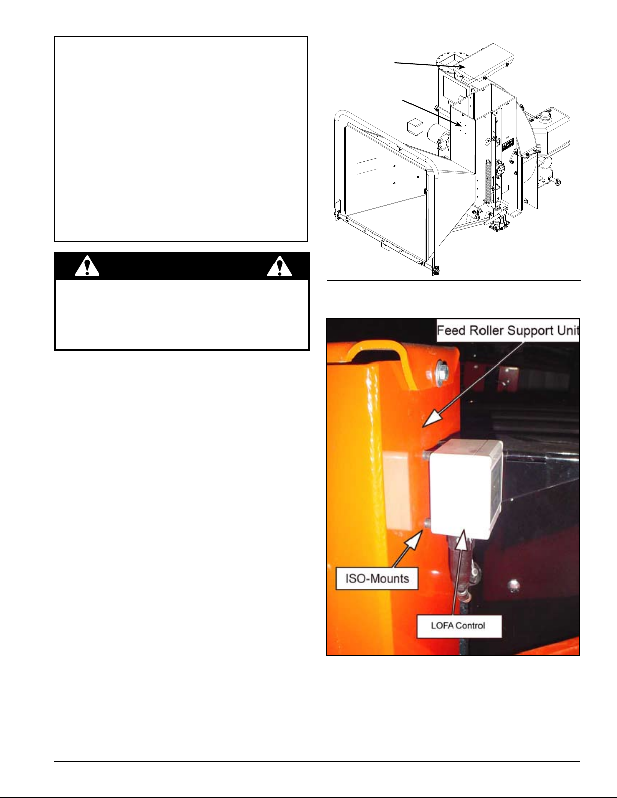
MOUNTING THE LOFA CONTROL
Remove upper belt guard. 1.
Remove the top cover from the Feed Roller Support 2.
unit. If the serial number is equal to or greater than
X01249, skip to STEP 6 (Figure 1).
Remove the back cover from the LOFA control, center it 3.
3-1/2” from the top on the front plate of the Feed Roller
Support housing and mark the position of the holes.
Drill four 1/4” holes (Figure 1).4.
Attach the ISO-Mounts to the controller back plate with 5.
the bolts and nuts provided (Figure 2).
Secure the back plate of the controller to the Feed 6.
Roller Support housing with a washer and one M4-0.7
nuts per bolt, apply locking adhesive and tighten.
Replace the Feed Roller Support cover.7.
Figure 1
Attach the LOFA Control to the back plate (Figure 2)8. .
Instruction Sheet
Figure 2
PN 73243
Rev. 022608
Page 2
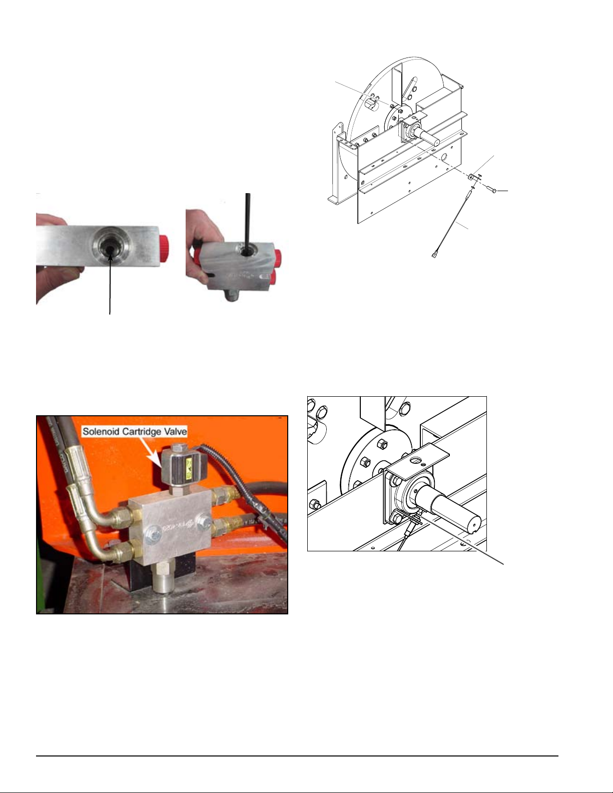
INSTALLING THE SOLENOID
SENSOR
BOLT, 1/2 X 2 HEX
SENSOR BRACKET
NUT, 1/2 CENTERLOCK
1/8" - 1/16"
GAP
CARTRIDGE VALVE
Model 76824 requires the installation of a cross over valve
and hoses. Cross over valve (12820) comes complete with
a solenoid cartridge.
Remove outer plug (using 5/16" allen wrench) from the 1.
top of the valve manifold.
Once the outer plug has been removed, using a 3/16 2.
allen wrench, extract the inner plug located in the relief
valve (Figure 3).
Figure 5
Figure 3, 3/16" inner plug
Replace the removed components with the new sole-3.
noid cartridge valve and coil.
Connect solenoid wiring to LOFA Control wiring har-4.
ness (Figure 4).
POSITIONING THE SENSOR
Position the sensor approximately 1/16” - 1/8” from the 1.
head of the bolt (Figure 6).
Replace the Belt Guard We ldment using 5/16” 2.
hardware.
Figure 6
INSTALLING THE SENSOR
Figure 4
Secure the sensor bracket with the lower left bearing 1.
bolt and position it (the sensor) so it aligns with the set
bolt (Figure 5).
Instruction Sheet
Page 3

ELECTRICAL INSTALLATION
WIRING SCHEMATIC
5
6
4
2
3
1
WIRE COLOR CODE LEGEND
O ORANGE
G GREEN
B BLACK
R RED
BL BLUE
BR BROWN
B
O
G
BR
B
PROXIMITY
SENSOR
B
BL
BR
7
BL
R
FUSE
8 AMP
R
POWER GROUND
B
COIL
CONN
CONN
O G
MODELS: CH6614H (72620), 74824 & 72825
Note: For Models CH6614H (72620) & 74824 (Honda Engines), note STEP 4 and refer to the wiring schematic.
Crimp a ring terminal onto the Black ground lead.1.
Drill a 3/16” hole in the trailer, close to the solenoid 2.
valve, and secure the ground wire with the #10 selftapping screw provided.
Connect the two-pin connector to the top of the valve 3.
coil.
Crimp a spade connector onto the Red wire in the 4.
Feed Sensor harness and connect to the Yellow wire
from the Kohler engine harness. For Honda engines,
the Red wire is attached to the black wire with a yellow
tracer coming from the engine.
Connect the socket connector to the LOFA control.5.
Secure wiring harness with cable ties as appropriate.6.
MOD E LS: CH911DH ( 729 2 8), 7294 2 &
CH922DH (74950)
Crimp a ring terminal onto the Black, Ground lead.1.
Drill a 3/16” hole in the trailer, close to the solenoid 2.
valve, and secure the ground wire with the #10 selftapping screw provided.
Connect the two-pin connector to the top of the valve 3.
coil.
Crimp a ring terminal to the Red wire in the Feed Sen-4.
sor harness and attach to “B” terminal on the back of
the Murphy Switch.
Connect the socket connector to the LOFA control.5.
Secure wiring harness with cable ties as appropriate.6.
Instruction Sheet
Page 4

FE E D S E NS O R P R OGR A MMI N G
INSTRUCTIONS
STEP 1. INITIATING PROGRAM MODE
Hold down the “S” button while turning the engine key to the “on”
position until “L” starts to flash on the LCD.
STEP 2. ENTER LOW (L = LOW) RPM
The low setting is the RPM speed where the feed roller stops.
The “up” arrow increases the RPM setting, while the “down” arrow
decreases the RPM setting. Setting the speed lower causes the
engine to lug down more before the feed roller stops.
Hold the appropriate (either up or down) arrow until the desired 1.
RPM speed is displayed (Recommend 1375 rpm).
Push the “S” button once with the desired RPM setting displayed 2.
to save.
NOTE: Do not choose a setting equal to or below zero.
STEP 3. ENTER NORMAL
(N = NORMAL) RPM
The normal setting is the RPM speed that the chipper rotor
usually rotates
Hold the appropriate (either up or down) arrow until the desired 1.
RPM speed is displayed (Recommend 1500 rpm).
Push the “S” button once with the desired RPM setting 2.
displayed to save.
ELECTRONIC FEED PARTS LIST (PN 73244)
PN DESCRIPTION QTY
12674 CONTROL, LOFA HYDRAULIC 1
12813 HARNESS, AUTO FEED 1
15602 WASHER, #6 SAE FLAT 4
15640 NUT, M4-0.7 ZP HEX 8
73242-12 BRACKET, PROXIMITY SENSOR 1
12828 CONNECTOR, #10 INSULATED RING 2
12829 CONNECTOR, #10 INSULATED FORK 3
12830 CONNECTOR, .25 INSULATED MALE 2
17320 STRAP, NYLON TIE-11” 4
16967 VALVE, SOLENOID CARTRIDGE 1
16968 COIL, SOLENOID VALVE 1
73243 INSTRUCTIONS, AUTO FEED 1
15282 BOLT 5/16*1 1/2 GR5 HEX CPS ZP 1
15225 SCREW, #10 X 3/4 HEX TAP SC 1
STEP 4. ENTER HIGH (H = HIGH) RPM
The high setting is not needed with this application.
Set to zero to deactivate.1.
Push the “S” button once with zero displayed to save.2.
STEP 5. ENTER RETURN
(RET = RETURN) RPM
The return setting is the RPM speed where the feed roller
restarts. The feed roller should restart before the rotor reaches
“normal” RPM to maximize chipper efficiency. Setting the speed
higher allows the engine to recover more before the feed roller
restarts.
Hold the appropriate (either up or down) arrow until the desired 1.
RPM speed is displayed (Recommend 1400 rpm).
WARNING
NOTE: WHEN APPROACHING THE END OF A LOG, IT
MIGHT BE NECESSARY TO MANUALLY OVERRIDE
THE AUTOMATIC FEED SENSOR. BE SURE TO PAY
ATTENTION TO THE ENGINE SPEED AND FEEDING OF
THE MATERIAL.
Instruction Sheet
www.bearcatproducts.com
ECHO BEAR CAT
237 NW 12th Street, West Fargo, ND 58078-0849
Phone: 701.282.5520 • Toll Free: 800.247.7335 • Fax: 701.282.9522
E-mail: service@bearcatproducts.com • sales@bearcatproducts.com
 Loading...