

Page 1

I
nstruction &
Owners Manual
6" & 8"
Chipper
and
Hydraulic
Feed
Models
Crary Company
Box 849
West Fargo, ND 58078
(701) 282-5520 (800) 247-7335
FAX: (701) 282-9522
71620
71825
72620
72825
Cat. No. 16681
Manual No. 1097
Page 2

Dear Bear Cat Customer,
Thank you for purchasing a Crary Bear Cat Chipper. The Bear Cat
Chipper is designed, tested, and manufactured to give years of
dependable performance. To keep your chipper operating at peak
efficiency, it is necessary to adjust it correctly and make regular
inspections. The following pages will assist you in the operation and
maintenance of your machine. Please read and understand this manual
before operating the chipper.
If you have any questions or comments about this manual, please call
us toll-free at 1-800-247-7335.
If you have any questions or problems with your chipper, please call or
write your local factory-authorized Bear Cat dealer.
Please Send Us Your Warranty Card
A warranty card is included in your owner's kit packaged with your
chipper. Please take the time to fill in the information requested on the
card. When you send your completed card to us, we will register your
machine and start your coverage under our limited warranty .
How to Contact
Bear Cat
A
DDRESS
Crary Bear Cat
237 NW 12th Street
PO Box 849
West Fargo, ND 58078
P
HONE
800-247-7335
701-282-5520
Fax: 701-282-9522
H
OURS
M-F , 8 a.m. to 5 p.m.
Central Time
Owner's Record
Please take a moment to record the
following information about your chipper. If
you need to call for assistance, please be
ready to provide your model and serial
numbers. This information will allow us (or
your dealer) to help more quickly when you
call.
Model Number
Serial Number
This safety alert symbol identifies important safety messages in this
manual. When you see this symbol, be alert to the possibility of personal
injury and carefully read the message that follows.
Serial Number Decal Location
Serial Number Decal
Be alert! Your Safety is Involved.
Page 3

Table of Contents
Safety Instructions 2
Assembly 4
Controls 5
Operation 7
Chipping 9
Service and Maintenance 10
Hydraulic Feed Assembly 14
Hydraulic Feed Operation 15
Hydraulic Feed Maintenance 16
Speed Sensor Trouble Shooting Guide 17
Troubleshooting 18
Replacement & Maintenance Chart 19
Specifications 20
Torque Chart
Standard tightening torque
for normal assembly
applications
A Service Tip
Warranty
BOLTS (SAE GR5) SCREWS
MIN. TORQUE MIN. TORQUE
SIZE (FT. LBS.) SIZE (FT. LBS.)
5/16"...................20 5/16" set.......................5
3/8".....................35
1/2".....................75
Follow the suggestions outlined in this manual. For adjustments, repair,
or service not covered in this manual, contact your nearest authorized
BEAR CA T dealer. Y our dealer is knowledgeable about your machine
and has a direct line to the factory for assistance.
1
Page 4

Safety Instructions for Operation
This chipper is designed and tested to offer reasonably safe service.
However, failure to operate it in accordance with the following safety
instructions MAY RESUL T IN PERSONAL INJUR Y!
Before Operating
Preparation
1. Become familiar with the owners manual before attempting to operate this
equipment.
2. Do not allow children to operate this equipment.
3. Do not operate this equipment in the vicinity of bystanders.
4 . Carbon monoxide can be extremely dangerous in enclosed areas; do not run
the machine in an enclosed area. The exhaust from the engine contains carbon
monoxide, which is colorless, odorless, and tasteless.
5. Do not allow hands, or any part of body or clothing inside the feeding chamber,
discharge chute, or near any moving part.
6. Before inspecting or servicing any part of the machine, shut off the power
source, disconnect the spark plug, and make sure all moving parts have come
to a complete stop.
1. Obtain and wear safety glasses at all times while operating the machine. One
pair of safety glasses is provided with each chipper.
2. Avoid wearing loose-fitting clothing.
3. Operate the machine only on a level surface.
4. Do not operate the machine on a paved, concrete, or hard gravel surface.
Operating on a hard surface may cause discharged material to rebound and
kickback. It will also cause increased machine vibration. Increased vibration
may cause the machine to move and will promote premature wear of parts or
loosening of fasteners.
5. Before starting the machine, visually check that all screws, nuts, bolts, and
other fasteners are properly secured. Once every 10 hours of operation, all
screws, nuts, bolts, and other fasteners should be checked with wrenches for
proper tightness to insure everything is in proper working condition.
Operation
2
1. Before starting the machine, make certain the cutting chamber is empty .
2. When feeding chipable material into the machine, be extremely careful to
exclude pieces of metal, rocks, bottles, cans, and other foreign objects.
3. If the cutting mechanism strikes any foreign object or if the machine should
start making an unusual noise or vibration, immediately shut off the engine
and allow the machine to stop.
a) Inspect for damage.
b) Replace or repair damaged parts.
c) Check for and tighten loose parts.
4. Do not allow processed material to build up in the discharge area; this may
prevent proper discharge and can result in kickback of material through the
feed opening.
Page 5

Safety Instructions
Cont.
5. Do not allow hands or other part of the body or clothing inside the feeding
chambers, discharge chute, or near any moving part.
6. Keep all guards and deflectors in place and in good working condition.
7. Always stand clear of the discharge area when operating this machine.
8. Keep your face and body back from the feed opening.
9. Do not over reach. Keep proper balance and footing at all times.
10. Do not transport or move machine while the machine is running.
11. If the machine becomes clogged, shut off engine. Allow machine to come to a
complete stop before clearing debris.
Additional Safety
Rules for Towable
Models
Maintenance and
Storage for Towable
Models
1. Before towing, rotate the chipper chute opening to face in the opposite
direction of the vehicle that is towing it. This will prevent the chipper chute
from projecting over the trailer wheels and striking foreign objects.
2. Lock the rotor by inserting a bolt or punch through the locking holes on the side
of the rotor housing.
3. Use a 2 inch trailer ball, and always connect safety chains. Make sure trailer
hitch bolts are tight and secure.
4. Maximum towing speed should not exceed 55 MPH. Tire pressure should be 60
psi; check wheel lug bolts periodically to be sure they are tight and secure.
5. Make sure that the jack stand on trailer is in the UP position to clear the
ground during towing. Place the jack stand on a level surface and secure it in
the DOWN position before use.
6. Shut off fuel supply to engine when towing.
1. When this equipment is stopped for servicing, inspection, storage, or to change
an accessory , disconnect the spark plug wire from the spark plug. Disconnect
battery.
2. Store the machine out of the reach of children and where gasoline vapors will
not reach an open flame or spark. For storage periods of three months or more,
drain the gasoline and dispose of it in a safe manner. Always allow the machine
to cool before storing.
3
Page 6
Assembly, Controls, and Engine Operation
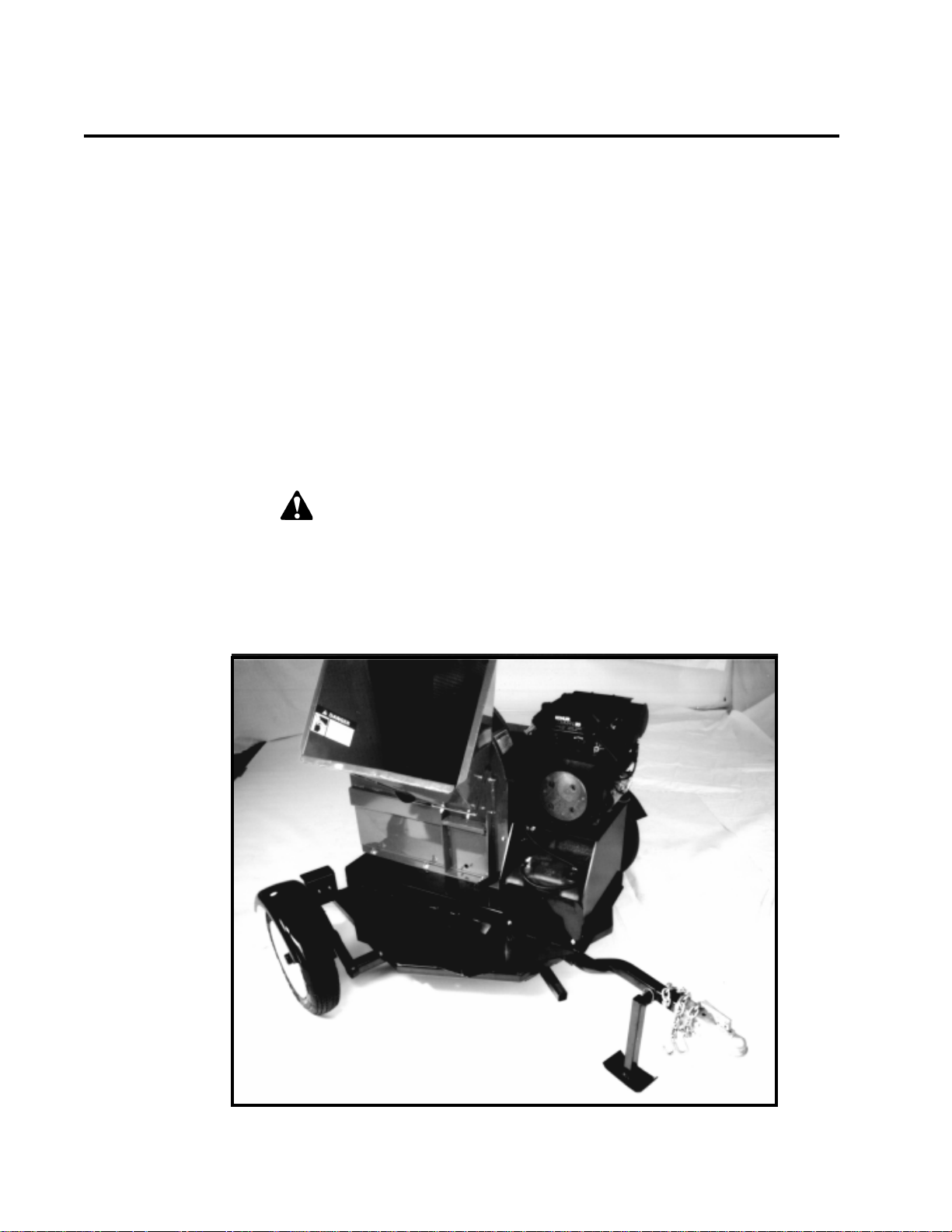
Assembly
See Figure 1
1. Remove from shipping crate.
2. Support the frame on wood blocks or other support device.
3. Mount the two tires and rims to the axle assembly with the lug nuts (supplied).
4. Mount the trailer hitch assembly to the frame using three 3/8 X 3-1/2 inch bolts
and locknuts (supplied).
5. Fasten the chipper chute to the main frame mounting bracket using eight 3/8 X
1 inch bolts and locknuts. Use three bolts on each side and two on the bottom.
6. Attach the blower discharge tube to the mounting flange on the chipper frame.
Half of the mounting clamp is already attached to the tube. Slide the tube into
the flange and tighten the bolts to secure it. Install the second half of the
clamp to the tube and flange. Rotate the tube 360 degrees and lock it in place
with the handle to make sure it is mounted correctly .
7. Install battery , connect positive and ground battery cables, and check battery
condition. Charge if needed.
Use caution when connecting battery cables near fuel. A spark could ignite
the fuel and cause a fire.
8. Fill the engine with oil (per instructions in supplied engine manual) and fill the
gas tank with gasoline.
9. Y our chipper should be ready to use.
Figure 1
4
Page 7

Controls: Engine
Dipstick
1. Engine Throttle: (Gasoline models only) changes engine speed. Turn knob
clockwise for full throttle operation. Turn knob counterclockwise for idle on
warm up. Turn knob fully counterclockwise to shut engine off. Refer to engine
manual for further engine operating instructions.
2. Engine Choke: (Gasoline models only) use when starting cold engine. Pull to
ON position when starting. Push lever to OFF position when engine is running.
Refer to engine manual for further engine operating instruction.
3. Key Switch: Located on engine case. Release switch as soon as engine is
running. Do not crank starter for more than ten seconds or damage could
result.
4. Other Engine Components: See Figures 2 and 3.
Air Cleaner
Oil Fill
Electric
Starter
Side Oil Drain Plugs
Figure 2
Fuel
Pump
Oil
Filter
Oil Cooler
Figure 3
5
Page 8
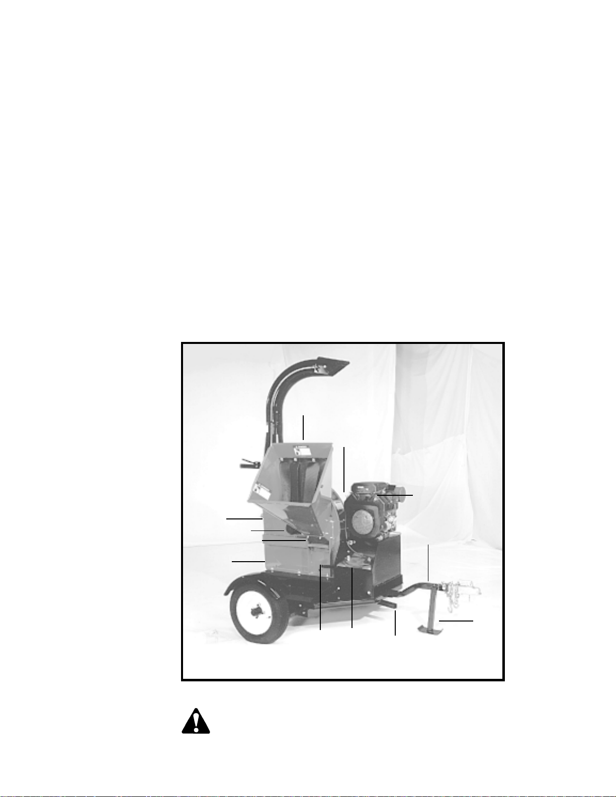
Controls Cont.
See Figure 4
5. Engine Fuel Tank: Use unleaded fuel—do not mix with oil.
6. Trailer Hitch: Always use 2 inch ball and safety chains.
7. Jack Stand: Always have in UP position and clear from ground when
moving. When is use, place in DOWN position on a level surface.
8. Engine Drive Belts and Shield: Never remove shields when in use.
9. Chipper Chute: Feed materials to be chipped through the chute.
10. Engine Controls
11. Rotor Access Cover: Used to remove chipper blades.
12. Engine Battery (not included)
13. Rotor Shaft End Cover: Covers rotor shaft and bearing. Has lock
assembly to lock in place while moving.
14. Clutch Foot Pedal: Used to engage rotor assembly drive belt.
15. Adjustable Chipping Anvil
16. Foot Pedal: Used to pivot machine 360 degrees.
11
12
13
15
9
14 5
Figure 4
8
10
6
7
16
CAUTION: The chipper rotor may continue to rotate even with the engine
stopped. Do not attempt any repair or adjustments until the entire
machine has come to a complete stop and spark plug wire is removed.
Never operate this machine without all safety shields in place.
6
Page 9

Engine Operation:
Starting
CAUTION: Move machine to a clear, level area outdoors before starting.
Do not operate machine on a paved, concrete, or gravel surface. Do not
operate in the vicinity of bystanders. Make sure cutting chamber is empty
before starting.
1. Before starting, fill engine with oil to the correct level. See engine manual
for operation and maintenance instructions.
Note: Some oil usage is normal. Check level with each use.
WARNING: Handle fuel (gasoline) with care. It is highly flammable. Always
use an approved container and fill tank outdoors. Never add fuel to a
running or hot engine.
2. Before starting, fill fuel tank with fresh, clean unleaded regular gasoline.
DO NOT MIX OIL WITH GASOLINE.
3. Place the throttle control midway between slow and fast positions. Place
the choke control to the ON position.
CAUTION: See operation/start-up decal by foot clutch pedal on machine
before starting.
4. Depress foot clutch pedal down, this will disengage drive belts and enable
engine to start.
5. Activate the starter switch. Release the switch as soon as the engine
starts. Do not crank over for more than 10 seconds.
6. Move choke lever to RUN position. After a short shut down, full choke
may not be necessary . If engine fails to start, move lever to RUN or partial
choke.
7. Once engine is running and no choke is needed, slowly let foot clutch
pedal up. This will engage drive belt and the rotor will turn.
8. If engine kills when engaging foot clutch pedal, either use more choke or
increase engine RPM.
9. When clutch is engaged, the foot pedal may vibrate or shake until the
engine and rotor have increased to full running RPM.
10. The chipper frame assembly can turn 360 degrees clockwise or
counterclockwise. Press down on the foot pedal located underneath the
frame near the tow hitch and the frame will pivot on the trailer to your
desired location. Let up on the foot pedal and the frame will lock into
place for use. The discharge tube can also turn 360 degrees to your
desired location.
WARNING: Return table to towing position and lock in place before moving
machine. Do not move chipper while machine is running.
Note: When restarting a warm engine after a short shut down, it may not be
necessary to use full choke. If the engine fails to start, move lever to run or
partial choke.
CAUTION: Obtain and wear safety glasses at all times when operating the
machine. Do not wear loose fitting clothing. The operator should always
wear heavy boots, gloves, pants, and shirt. Use common sense and
practice safety to protect yourself from branches, sharp objects, and other
harmful objects.
WARNING: Do not leave machine unattended or inspect or service unless
the engine is stopped and the spark plug wire is removed from the spark
plug.
7
Page 10

Engine Operation:
Stopping
1. Move throttle to SLOW position.
2. Depress foot clutch pedal.
3. Move throttle to STOP position (or shut off key switch) and remove spark
plug wire from spark plug.
4. Allow machine to come to a complete stop. Y ou may release the foot
clutch pedal to help slow the rotor once the engine has stopped running.
Note: The heavy rotor will continue to turn for some time after the engine has
been shut off. Y ou can tell that the rotor has stopped when no noise or
machine vibration is present. Inserting a branch into the chipper chute to
contact the blades will slow the rotor and shorten stopping time.
CAUTION: Obtain and wear safety glasses at all times when operating
the machine. Avoid wearing loose fitting clothing. Always wear heavy
boots, gloves, pants, and shirt. Use common sense and practice
safety to protect yourself from branches, sharp objects, and other
harmful objects.
CAUTION: Move machine to a clear, level area outdoors before
starting. Do not operate machine on a paved, concrete, or gravel
surface. Do not operate in the vicinity of bystanders. Make sure cutting
chamber is empty .
8
Page 11

Chipping
WARNING: Keep face and body away from the feed opening. Do not
overreach. Keep proper balance and footing at all times.
The Bear Cat chipper is designed to chip a variety of materials into a more
readily decomposing or handled condition. The following guidelines can be
used to help you get started.
1. Select limbs that are up to 8 inches in diameter. T rim side branches that
cannot be bent enough to feed into the chipper chute. Hold small diameter
branches together in a bundle and fed in simultaneously .
2. Place limb, butt end first, into the chipper chute until it contacts the
chipper blades. The actual feed rate of the limb into the chipper depends
on the type of material fed and sharpness of the cutting blades.
Alternately insert and retract the limb or insert continuously at a rate that
will not kill the engine or stall the tractor.
• Rotating the branch to improve cutting action.
The chipping blades dull with use and require periodic sharpening. Refer to
Service and Maintenance, "Sharpening Chipper Blades" for instructions.
Figure 5
9
Page 12
Service and Maintenance
WARNING: Before inspecting or servicing any part of the machine, shut off
the power source, disconnect the spark plug wire from the spark plug, and
make sure all moving parts have come to a complete stop. The chipping
blades are sharp! Use care when working on machine to avoid injury .
WARNING: The rotor assembly has a lock mechanism. When working on
the rotor assembly , use the lock mechanism at all times. Remove plastic
bearing cover under chipper chute. There is a hole in the rotor jack shaft
and a matching hole in the bracket mounted to the rotor bearing front side.
Install a punch through the rotor shaft and bracket to lock the rotor in
place.
Check the engine oil, and change the oil and filter as recommended in the
manual. Service and replace the air cleaner as recommended.
Sharpening Chipper
Blades
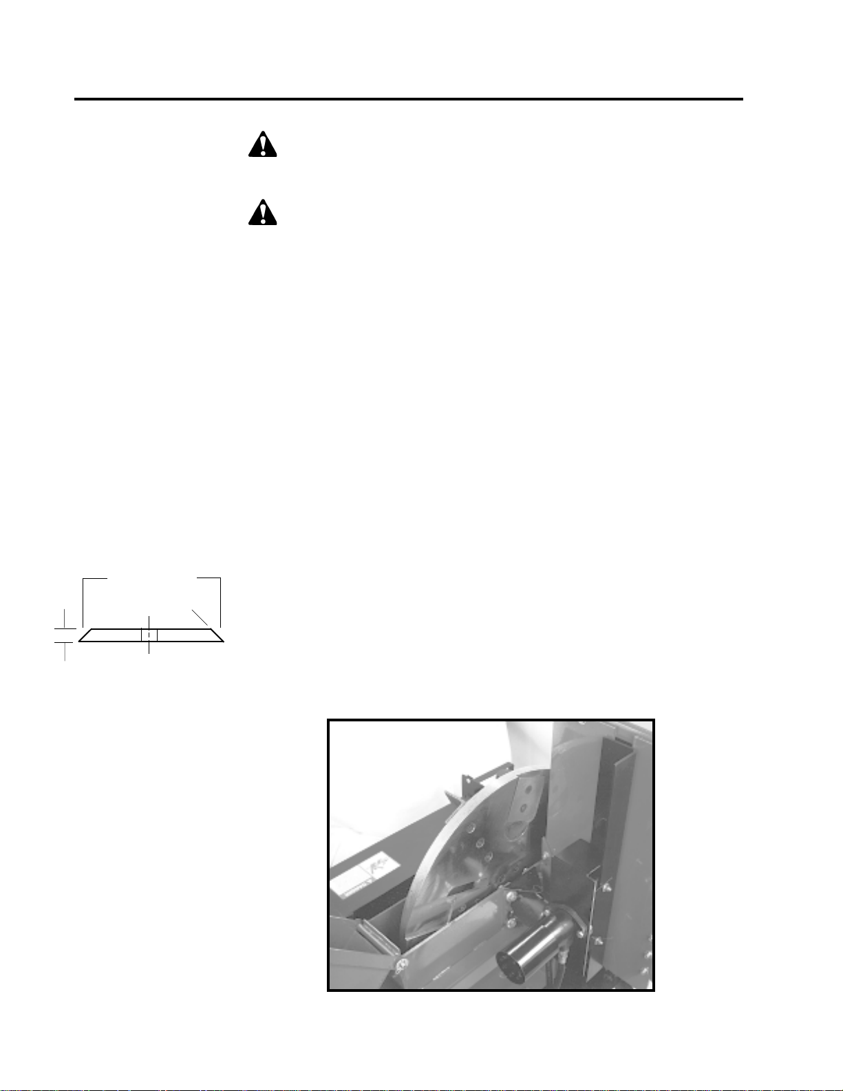
See Figure 7
Sharpening
Edges
⋅⋅
45
⋅
t
0.38
s
t
⋅⋅
Figure 6
The chipper blades dull, making chipping difficult. The chipper blades are two
edged. When the first edge dulls, flip the blade to use the sharp second edge.
After both edges are dull, sharpen the chipper blades. It is recommended that
the chipper blades are sharpened every 5-15 hours of chipper operation. T o
remove the chipping blades for sharpening:
1. Remove the two 3/8 inch retaining bolts holding the access cover to main
frame assembly .
2. Tilt access cover over to allow rotor access. Rotate the rotor so that the
bolts holding a chipping blade are most accessible.
3. Remove the two hex head bolts holding the blade itself. Repeat for all four
blades. The four chipping blades have two edges per blade and can be
reversed one time each before sharpening. Reinstall chipping blades and
proceed with chipping.
T o grind the angled edge of the chipping blade to 45 degrees (see figure 6):
t
Grind the blades on a bench grinder or have them sharpened by a professional.
Be careful when grinding so that the blade material does not get too hot and
change color–this will remove the blade's special heat treated properties. Use
short grinding times and cool with water. T ry to remove an equal amount off
each blade to maintain balance. Replace the chipping blades and tighten bolts
to 75 ft. lbs.
10
Figure 7
Page 13

Setting Chipping
Blade Clearance
The four edged chipping blades should clear the chipping anvil located directly
under the chipper chute by 1/16 inch to 1/8 inch. The chipping anvil is
adjustable and reversible.
To Adjust:
Adjusting Drive
Belts
1. Lift rotor access cover and expose rotor (see figure 7). Loosen the three
1/2 inch bolts that hold the chipper anvil to the frame.
2. Measure the amount of clearance between chipping blade and chipping
anvil from inside of housing.
3. Adjust inward or outward to desired measurement.
4. Tighten bolts on chipping anvil to 75 ft. lbs. and resume operation.
If chipping anvil edge is damaged or worn unevenly , remove the three bolts
holding the anvil and use one of the other three edges. Adjust for correct
measurement.
Check the condition of the drive belt annually or after every 30 hours of
operation, whichever comes first. If the belt is cracked, frayed, worn, or
stretched, replace it. Only replace belt with original banded type belt, do not
use single type belts. T o adjust the belt, proceed as follows:
1. Depress foot clutch pedal. Shut engine off and disconnect battery cables.
2. Remove large belt guard (three 5/16 inch bolts).
3. Adjust the eyebolt that anchors the idler spring to adjust belt tension.
Tighten the eyebolt until the belt deflection at the center of the belt is
7/16" when a 20 lb. load is place against the belt (see figure 8).
Replacing Drive
Belt
Figure 8
4. Replace belt guard.
5. Start engine and test belt for looseness. Replace the belt if no adjustment
is left.
1. Remove large belt guard (three 5/16" bolts).
2. Lift belt idler pulley off drive belt and remove drive belt from pulleys.
3 . Install new belt on pulleys and lower belt idler. Check alignment of pulleys
and adjust if needed.
4. Adjust the eyebolt that anchors the idler spring to adjust belt tension.
Tighten the eyebolt until the belt deflection at the center of the belt is
7/16" when a 20 lb load is place against the belt (see figure 8).
5. Replace belt guard.
6. Depress foot clutch pedal, start engine, release foot clutch pedal to
engage belt, and test unit. Readjust pulleys and belt tension if needed.
7/16" Deflection
11
Page 14

Replacing Drive
Belt-Hydraulic
Models
1. Remove large belt guard (three 5/16" bolts).
2. Loosen bolts on hydraulic pump and remove belt.
3. Lift belt idler pulley off drive belt and remove drive belt from pulleys.
4 . Install new belt on pulleys and lower belt idler. Check alignment of pulleys
and adjust if needed.
5. Adjust the eyebolt that anchors the idler spring to adjust belt tension.
Tighten the eyebolt until the belt deflection at the center of the belt is
7/16" when a 20 lb load is place against the belt (see figure 8).
6. Replace hydraulic pump belt. Readjust hydraulic pump belt tension by
sliding the hydraulic pump in the mounting slots. Tighten bolts.
7. Replace belt guard.
8. Depress foot clutch pedal, start engine, release foot clutch pedal to
engage belt, and test unit. Readjust pulleys and belt tension if needed.
WARNING: If the machine becomes plugged, depress foot clutch
pedal, shut off the engine, disconnect the spark plug wire, and allow
the machine to come to a complete stop before clearing debris. Do not
operate the machine without proper guards and screens in place.
Feeding too large or too much chipable material at once may plug the chipper.
T o clear plugged rotor , proceed as follows:
Clearing Plugged
Rotor
Repairing or
Replacing Rotor
Bearings
1 . Depress foot clutch pedal and stop engine. Release foot clutch pedal when
engine is stopped.
2. Remove the two 3/8" retaining bolts holding the access cover to the main
frame assembly .
3. Lift up rotor access cover.
4. Clean the debris out the chipper rotor. T urn the rotor by hand to be sure it is
free to rotate.
5. Close rotor access cover and replace bolts.
6. Depress foot clutch pedal, and start engine. Release foot clutch pedal
when engine is running to engage drive belt. Resume operation.
CAUTION: Remember to use rotor shaft lock when working on rotor.
1. Remove the two 3/8 inch retaining bolts holding access cover to main
frame assembly . T ilt access cover over to allow rotor access.
2. Remove large belt guard (three 5/16 inch bolts).
3. Lift belt idler pulley off drive belt and remove belt from pulleys. Using the
push bolts from the bushing, remove the bushing and pulley from the rotor
shaft.
12
WARNING: The rotor assembly has a lock mechanism. When working
on the rotor assembly , use the lock mechanism at all times. Remove
plastic bearing cover under the chipper chute. There is a hole in the
rotor jack shaft and a matching hole in the bracket mounted to the
rotor bearing front side. Install a punch through the rotor shaft and bracket to
lock the rotor in place.
Page 15

4. If a rotor bearing needs repair, it is best to remove the complete rotor assembly from chipper frame.
5. Using an overhead hoist or lifting device, remove the four 1/2 inch bolts on
each rotor bearing and lift the rotor assembly completely out of the frame. The
complete rotor assembly is 275 lbs.
6. Once the rotor assembly is out of the frame, both bearings can be removed by
a puller and replaced on the shaft.
7. Use the overhead hoist or lifting device to return the complete rotor assembly
to the chipper frame.
8. Install the four 1/2 inch bolts on each bearing to secure them to the frame.
Tighten bolts to 75 ft. lbs.
9. Replace drive belt on pulleys and lower belt idler. Check alignment of pulleys
and adjust engine if needed.
10. Check belt tension before start-up. Adjust the eyebolt that anchors the idler
spring to adjust the belt tension. Tighten the eyebolt until the belt deflection at
the center of the belt is 7/16" when a 20 lb. load is placed against the belt (see
figure 8, page 11 ).
11. Close cover and replace bolts.
12. Replace belt guard and resume operation.
13. Depress foot clutch pedal, start engine, release foot clutch pedal to engage
belt, and test unit. Readjust pulleys and belt tension if needed.
Greaseable
Bearings and Pivots
Other Service Tips
Trailer Service T ips
• Hydraulic units remove hydraulic pump and belts prior to step 3 and replace
prior to step 12.
The models have five greaseable bearings and pivots that require grease every 50
hours:
• Two bearings on the rotor shaft.
• One greaseable bushing on the foot clutch pedal pivot.
• One grease zerk on idler pivot.
• One grease zerk on discharge chute.
1. Service engine according to engine manual. Change engine oil and filter as
recommended in manual.
2. Every 10 hours of operation, all bolts and other fasteners should be checked
for correct torque.
1. Check wheel bolt torque every 10 hours of towing use.
2. Check air pressure in tires every 10 hours of towing. Maximum 60 psi.
3. Check and repack wheel bearings with grease every 12 months.
4. When towing, use a 2 inch trailer ball, and always connect the safety chains.
Make sure trailer hitch bolts are tight and secure.
13
Page 16

Hydraulic Feed Assembly (For Units With Optional Hydraulic Feed)
Fluids
Pump Component
Locations
Hydrostatic Pump
Start Up Procedure
Handle pressurized hydraulic fluid carefully . Escaping pressurized
hydraulic fluid can have sufficient force to penetrate your skin causing
serious injury . This fluid may also be hot enough to burn. Serious
infection or reactions can develop if proper medical treatment is not
administered immediately .
Premium hydraulic fluids containing high quality rust, oxidation, and foam
inhibitors are required. These include premium turbine oils, API CD engine oils
per SAE J183, M2C33F or G automatic transmission fluids meeting Allison C3 or Caterpillar TO-2, and certain specialty agricultural tractor fluids.
Follow this start-up procedure when starting a new installation or when restarting an installation in which the hydrostatic pump has been removed from the
system.
1. Before starting the hydrostatic pump, make sure all system components
(reservoir, fittings, etc.) are clean.
Hydrostatic pressure
controlled by the
crossover relief valve is
factory set at 1500 PSI.
A 2000 PSI shim kit is
available for extreme
conditions.
2. Fill the reservoir with recommended hydraulic fluid, which should be
filtered before entering the reservoir.
3. The inlet line leading from the reservoir to the charge pump must be filled
before start-up. Loosen the fitting on this inlet line until oil bleeds out.
Warning! Do not start engine unless pump is in neutral or detent
position on the cable.
4. Start the engine and run at the lowest possible RPM.
5. As air is purged from the unit, the oil level in the reservoir will drop and
bubbles may appear in the fluid. Refill the reservoir as necessary .
6. Run the unit and move the control arm in both directions for several
minutes until any remaining air is purged from the unit. Refill the reservoir
as necessary .
Note: A motor fitting may have to be loosened and oil-bled to remove air
from the system (use same procedures as steps 3-5).
7. Check to ensure feed roller stops when control arm is in the neutral
position. Adjust the cable clevis or anchor if the feed roller doesn't stop.
8. Shut down the engine, check for and correct any fluid leaks, and check
the reservoir level. Add fluid if necessary . The hydrostatic pump is now
ready for operation.
14
Page 17

Hydraulic Feed Operation
Please read and
follow all safety
instructions in this
manual. Failure to
operate the chipper in
accordance with the
safety instructions MAY
RESUL T IN PERSONAL
INJURY!
Control Arm
Operation
1. Start the chipper engine. Bring the chipper up to operating speed. See
"Controls and Operation" section for starting, operation, and stopping
instructions.
2. Engage the hydraulic feed by moving the control arm as shown below. In
the forward direction, the feed rate increases as the arm is moved.
3. Feed the branch (up to 8 inches in diameter).
4. If the chipper jams, reverse the feed by moving the control arm in the
reverse direction. Remove the branch and rotate it before reinserting it into
the chute again.
Reverse
s
Neutral
s
Forward
Control
Arm
Hydraulic Feed
Component
Locations
Reservoir
Hydrostatic
Pump
Roller Assembly
Hydraulic
Motor
Chipper
Chute
Crossover
Relief
Valve
15
Page 18

Hydraulic Feed Maintenance
Maintenance
Hydrostatic Pump
Troubleshooting
Before servicing or
repairing any of the
hydrostatic feed
components (pump,
motor, and/or relief valve),
contact your dealer or
factory service
department. Warranty on
these items may be void
without prior authorization.
Note: Check the reservoir daily for proper fluid level, the presence of water
(noted by a cloudy to milky appearance, or free water in bottom of reservoir),
and rancid fluid odor (excessive heat).
The hydrostatic pump normally does not require regular fluid changes. The
system filter should be changed at 250 hour or annual intervals. The fluid and
filter should be changed and system cleaned if the fluid becomes contaminated with foreign matter (water, dirt, grease, etc.) or if the fluid has been
subjected to temperature levels greater than the maximum recommended.
There is a greaseable bearing on each side of the main jack shaft on the main
hydraulic feed housing. Grease periodically .
Symptom
Will not attain normal feed rate.
Will not feed when control arm
is moved.
Feed rate is sluggish under
load.
Probable Cause
Engine not operating at correct speed.
Control linkage damaged or
binding.
Bypass valve stuck partially
open. (Problem in one direction only.)
Control linkage damaged or
not connected.
Drive between engine and
pump damaged.
Pump low on fluid.
Loose drive belt between
engine and pump.
Pump low on fluid.
Large amount of water in hydraulic fluid (evaporates when
hot, resulting in low fluid level).
Suggested Remedy
Repair engine governor.
Repair control linkage.
Repair bypass valve.
Remove foreign material from
valve.
Repair or reconnect control
linkage.
Repair drive (replace broken
belt, repair sheared key, repair splined coupling, etc.).
Refill reservoir. Purge air from
transmission.
Tension drive belt (replace if
necessary).
Refill reservoir. Purge air from
transmission if necessary.
Drain fluid from reservoir and
unit, replace filter element,
and refill with new fluid.
16
Hydraulic Feed will not pull in
logs over 4" in diameter, or
continuously stalls or stops.
Hydraulic system overloading
and causing system to go
over relief.
Caution: Hydraulic systems contain
fluid under high pressure. Never check
for leaks with your hands. Relieve
pressure before disconnecting any
hydraulic lines.
Check relief pressure in system with a pressure gauge
rated to 2500 psi. (system set
by factory at 1750 psi.)
Page 19

17
Page 20

Troubleshooting
Problem
1. Rotor does not turn
2. Hard to feed chipper
or excessive power
needed to chip
3. Chipper requires
excessive power or
stalls
Probable Cause
a) Obstructed
discharge
b) Plugged rotor
a) Obstructed
discharge
b) Dull chipper blades
c) Improper blade
clearance
a) Obstructed
discharge
b) Plugged rotor
c) Green material will
not discharge
Suggested
Remedies
a) Use branch or
similar object to
clear discharge
b) Clear rotor
a) Use branch or
similar object to
clear discharge
b) Sharpen blades
c) Adjust clearance
a) Use branch or
similar object to
clear discharge
b) Clear rotor , feed
material into
shredder more
slowly
c) Alternately feed dry
material, or allow
material to dry
Reference
Service and Maintenance
Service and Maintenance
Service and Maintenance
4. Drive belts
squealing or
smoking
5. Vibration while
running
6. Engine dies or runs
poorly
a) Plugged rotor
b) Loose or worn belts
a) Drivehead vibration
b) Rotor out of balance
a) Engine problems
a) Clear rotor
b) Adjust belt tension
or replace belts if
needed
a) Check drive belts
and pulleys for bad
or worn spots.
b) Inspect rotor for
broken or missing
chipper blades and
paddles. Repair if
needed.
Check rotor to see if
it wobbles
Check to see if rotor
is assembled
correctly
a) Contact local engine
service center
Service and Maintenance
Service and Maintenance
18
Page 21

Replacement & Maintenance Chart
Note: When ordering replacement parts, be sure to identify the
Model and Serial number of the machine.
Replacement Parts Ordered
Date Part Ordered
Date Part Replaced
Replaced By
Checked By
19
Page 22

Specifications
Overall Size (LxWxH)
Max. Chipper Cap. (dia.)
Chipper Blade Qty .
Rotor Speed
Rotor Size
Rotor Weight
Rotor Shaft Diameter
Discharge Size
Drive Type
Belt Size
Weight (Lbs.)
Wheel Base
Tire Size
Fuel T ank Cap. (Gal.)
Model 71620
76 x 80 x 90"
6"
4 Reversible T ool Steel
1500 RPM
30" Dia. x 1.25"
275 lbs.
1.75"
8"
Belt
3B83
1445
66"
5.31-12
6
Model 72620
93 x 80 x 90"
6"
4 Reversible T ool Steel
1500 RPM
30" Dia. x 1.25"
275 lbs.
1.75"
8"
Belt
3B83
1865
66"
5.31-12
6
Model 71825
76 x 80 x 90"
8"
4 Reversible T ool Steel
1500 RPM
30" Dia. x 1.25"
275 lbs.
1.75"
8"
Belt
3B83
1450
66"
5.31-12
6
Model 72825
93 x 80 x 90"
8"
4 Reversible T ool Steel
1500 RPM
30" Dia. x 1.25"
275 lbs.
1.75"
8"
Belt
3B83
1870
66"
5.31-12
6
Engine
Specifications are subject to change because of design modifications.
Kohler 20 HP
Kohler 20 HP
Kohler 25 HP
Kohler 25 HP
20
Page 23

Chipper and Hydraulic Feed Limited Warranty
Crary Bear Cat Chipper models 71620, 71825, 72620, and 72825 are warranted for one year from
date of sale.
Within the above stated period, Crary Co. will replace any part(s) found to be defective in material
and/or workmanship, after the receipt of the part in our plant. Labor costs to replace these defective
parts will be paid at a Crary established labor rate and time allowed (flat rate) for repair. All
transportation charges incurred in shipping part(s) are the responsibility of the purchaser.
This warranty is void in the case of accidents, failure to perform normal maintenance, or failure to
follow those instructions listed in the service manual. This warranty is also in lieu of all other
expressed warranties and voids any implied warranty as to the merchantability or fitness of the
product for a particular purpose and of any other obligation on the part of Crary Co. Some states do
not allow limitations on how long the implied warranty lasts, so the above limitation may not apply to
you.
This warranty applies only to parts or components which are defective, and does not cover
necessary repair due to normal wear, misuse, accidents, or lack of proper maintenance. This
includes belts, pulleys, and chipper blades. Regular routine maintenance of the unit to keep it in
proper operating condition is the responsibility of the owner.
All warranty repair reimbursable under the Crary Co. warranty must be performed by an authorized
Bear Cat service dealer using Bear Cat approved replacement parts. Repair or attempted repair by
anyone other than an authorized Bear Cat service dealer is not reimbursable under the Crary Co.
warranty . In addition, these unauthorized repair attempts may result in additional malfunction, the
correction of which is not covered by warranty.
Crary Co. is not liable for indirect, incidental, or consequential damages in connection with the use of
this product including any cost or expense or providing substitute equipment or service during
periods of malfunction or non-use.
Some states do not allow the exclusion of incidental or consequential damages, so the above
exclusion may not apply to you. This warranty gives you specific legal rights. You may also have
other rights which vary from state to state.
Be sure to note the Chipper serial number in any correspondence with Crary Co. or any authorized
Bear Cat dealer. The serial number is located on the rotor assembly cover.
Page 24

HEAL TH WARNING
GASOLINE, DIESEL, AND
OTHER PETROLEUM PRODUCTS
Harmful or fatal if swallowed.
Long-term exposure to vapors has caused cancer in
laboratory animals.
• Avoid prolonged breathing of vapors.
• Keep face away from nozzle and gas tank/container
opening.
• Never siphon by mouth.
Failure to use caution may cause serious injury or illness.
W ARNING
CHEMICALS KNOWN TO THE STATE OF CALIFORNIA TO CAUSE CANCER, BIRTH DEFECTS, OR
OTHER REPRODUCTIVE HARM ARE FOUND IN
GASOLINE, DIESEL, CRUDE OIL, AND MANY OTHER
PETROLEUM PRODUCTS AND THEIR V APORS, OR
RESULT FROM THEIR USE.
READ AND FOLLOW LABEL DIRECTIONS AND USE
CARE WHEN HANDLING OR USING ALL PETROLEUM PRODUCTS.
ENGINE EXHAUST FROM THIS PRODUCT CONT AINS CHEMICALS KNOWN TO THE ST A TE OF CALIFORNIA TO CAUSE CANCER, BIRTH DEFECTS, OR
OTHER REPRODUCTIVE HARM.
Box 849
West Fargo, ND 58078
(701) 282-5520 (800) 247-7335
FAX: (701) 282-9522
http://www.crary.com
 Loading...