

Page 1
Instructions
REMOVE
DISCHARGE
DOOR
REMOVE
ROTOR
SHAFT END
CAP
MOUNTING
PLATE
SEAL
SUBJECT: TWO SPEED BLOWER
WITH 8-BLADE FAN, KIT # 71110
FITS MODELS: SC5540 (70054)
AND SC5614 (71020)
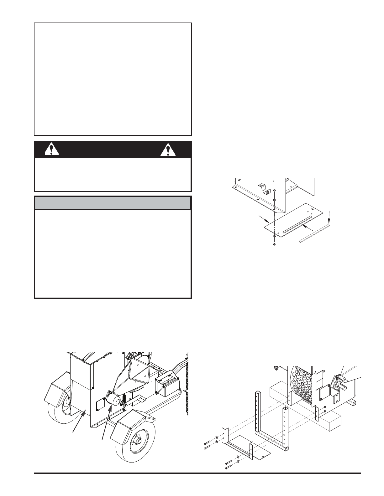
WARNING
Before inspecting or servicing any part of this machine,
shut off power source, and make sure all moving parts
have come to a complete stop.
NOTE
INSTALL BELT GUARD SUppORT pLATE
Two support plates are provided with the kit. One support
plate is for towable models, the other is for PTO models.
Select the appropriate plate for your machine.
TOWABLE MODELS
The mounting plate measures 16-1/4 x 7-1/2 inches. It
has key stock welded to one end.
NOTE: If your model does not have predrilled mounting
holes, align the mounting plate on the bottom of the
chipper/shredder, mark the positions of the holes on the
bottom of the chipper/shredder frame, and drill two 3/8"
holes through the metal on the frame.
To mount the plate:
Apply the seal to the plate as shown below.1.
Align the mounting plate with the 3/8" holes on the 2.
bottom of the chipper/shredder.
Attach the mounting plate to the frame using 3/8" x 1" 3.
bolts, washers, and nuts as shown below.
Before mounting the blower to the towable chipper/
shredder, we recommend moving the axle to the rear
position on the trailer base as follows:
Raise the trailer so that the wheels clear the 1.
ground.
Place blocks under the unit to suppport it.2.
Remove the bolts holding the axle to the trailer. 3.
Position the axle so that the bolt holes align with 4.
the two rear holes on the trailer base.
Attach the axle with the bolts and torque to the 5.
proper setting.
BEFORE INSTALLING
Remove the discharge door and rod. A new rod is 1.
provided with the kit.
Remove the rotor shaft end cap as shown below. The 2.
hardware will be used later.
pTO MODELS
The mounting plate has angled supports that bolt on to
the chipper/shredder support leg.
To mount the plate:
Support the discharge end of the chipper/shredder 1.
by inserting blocks under the frame until the blocks
support the weight of the chipper/shredder.
Remove the four bolts that attach the leg stand to the 2.
chipper/shredder.
Slide the mounting plate onto the leg stand.3.
Reattach the leg stand to the front of the chipper/4.
shredder with four (4) 3/8" x 2-1/2" bolts, washers,
and nuts as shown below.
Instruction Sheet
PN 71120
Rev. 121608
1
Page 2
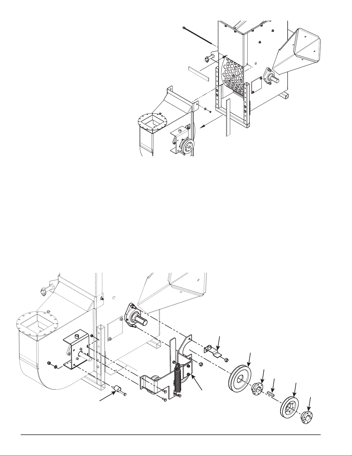
ATTACh BLOWER TO ChIppER/ShREDDER
IDLER
ASSEMBLY
6.6” PULLEY
BUSHING
KEY
5.2” PULLEY
BUSHING
FRONT
BELT GUIDE
REAR BELT GUIDE
Attach foam seals to the top of the chipper/shredder 1.
opening and side lips of the blower as shown.
Hold the blower up to the chipper/shredder frame, 2.
install the new rod, and secure with a 5/16" lock nut
on each end. The blower should rest firmly on the
chipper/shredder frame and mounting plate previously
installed.
INSTALL IDLER ASSEMBLy
Do not remove the two remaining nuts that secure the bearing.1.
Place the idler assembly over the rotor shaft bolts. Secure the assembly with the 2. bottom 1/2" nut that was removed
when the rotor shaft end cap was removed. The top nut will be screwed on later.
Align the opposite end of the assembly with the mounting holes on the blower mounting plate. Secure with two (2) 3.
5/16" x 1-1/4" bolts, nuts and washers.
Attach the split bushing to the 6.6" pulley. Follow the Reverse Mount instructions provided with the bushing and 4.
torque to 9 ft-lbs (108 in/lbs). Slide the pulley onto the rotor shaft.
Mount the inside belt on the 6.6" pulley and connect this belt to the inside (3.6") blower shaft pulley.5.
Align the 6.6" pulley with the inside (3.6") blower pulley using a straightedge. Make any necessary adjustments by 6.
sliding the 6.6" pulley on the rotor shaft. Tighten the 6.6" pulley bushing securely.
Attach the split bushing to the 5.2" pulley. Follow the Reverse Mount instructions provided with the bushing and 7.
torque to 9 ft-lbs (108 in/lbs).
2
Instruction Sheet
Page 3
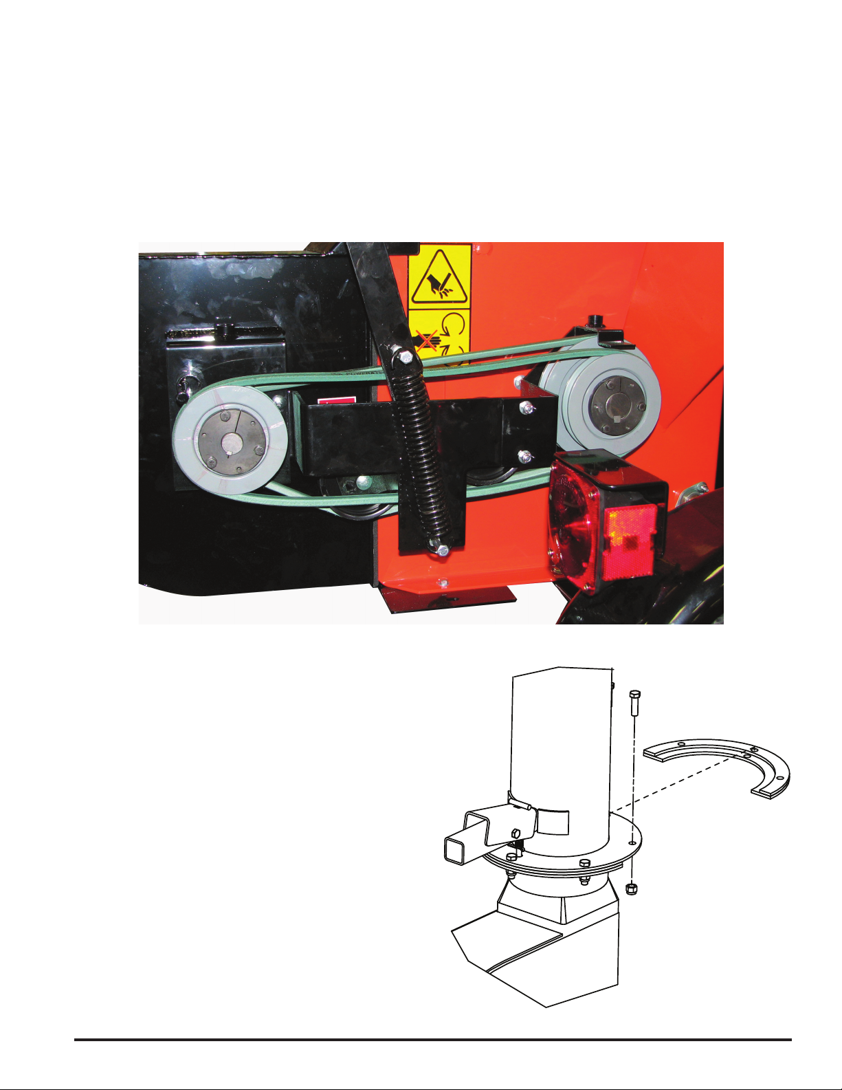
Slide the pulley onto the rotor shaft so approximately 1.8" of the pulley extends past the end of the shaft. Mount the 8.
outside belt on the 5.2" pulley and connect it to the 5" blower pulley. Align the small pulley to the 5" blower pulley
with a straightedge. Tighten the 5.2" pulley securely.
Attach the front belt guide to the top rotor shaft bolt. Replace nut and tighten securely.9.
Insert the rear belt guide into the hole next to the blower pulleys. Adjust the guide for a 3/16" clearance from the top 10.
surface of the belt and tighten.
COMpLETED pULLEy INSTALLATION
INSTALL DISChARGE TUBE
Half of the mounting clamp is already attached to the
discharge tube.
Slide the discharge tube over the mounting flange on 1.
the blower housing and tighten the bolts to secure it.
Attach the second half of the clamp to the tube and 2.
flange with 3/8 x 1-1/4" bolts and nuts.
Rotate the tube 360 degrees and lock it in place with 3.
the handle to make sure it is mounted correctly.
Instruction Sheet
3
Page 4
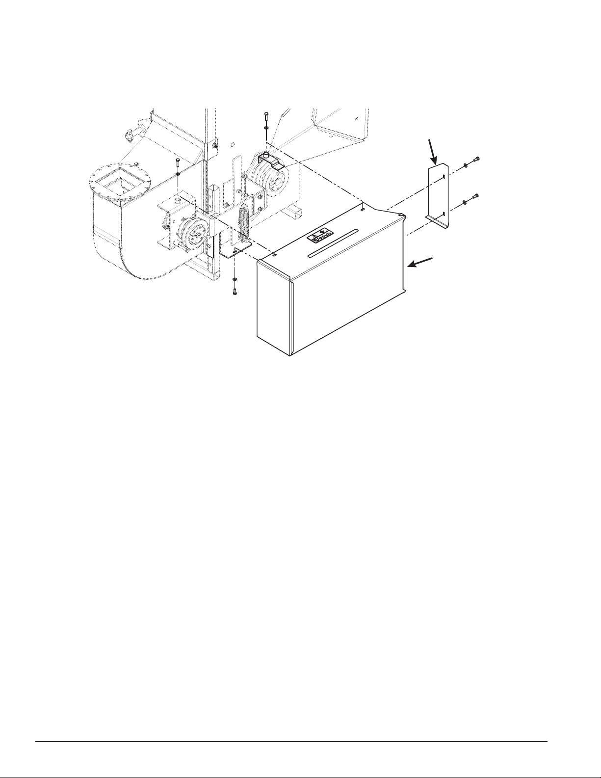
REpLACE FRONT BELT GUARD
FRONT GUARD
SIDE PIECE
FRONT
GUARD
Place front guard over speed adjustment lever.1.
Secure the top of the front guard with two (2) 5/16 x 1" bolts.2.
Secure the bottom of the front guard to the mounting plate with one (1) 5/16" x 3/4" bolt.3.
Attach the front guard side piece with two (2) 5/16 x 3/4" bolts.4.
OpERATION
See the chipper/shredder owner's manual for starting procedures and additional safety instructions before using the
two-speed blower.
The two-speed blower is designed to be used primarily with the chipper. When using the shredder, limit the size of the
material to 1/2" in diameter and 24" long sticks or twigs to avoid plugging the machine. Smaller diameter discharge
screens can also be used to help prevent plugging.
NOTE: Always start the chipper/shredder with the two-speed blower control lever in SLOW speed.
ChIppING
Adjust the discharge tube and spout • before operating.
Select limbs that are up to 5 inches in diameter. Trim side branches that will not fit into the chipper chute.•
Place limb, butt end first, into the chipper chute until it contacts the chipper blades. •
The actual feed rate of the limb will depend on the type of material fed and sharpness of the chipping blades. •
Insert the limb at a rate that will not kill the engine or stall the tractor. •
Rotating the branch as it is fed in will improve the cutting action. •
The chipper blades will become dull with use and will require periodic sharpening. Refer to the owner's manual for •
instructions.
ShREDDING
Place material to be shredded (grass, leaves, garden refuse, twigs, etc.) into the hopper. If necessary, use a leaf tamper,
branch, or similar object to push the material through the inlet brushes. If material is damp, insert small sticks or twigs
into the shredder to help prevent buildup.
FAST SpEED
Use the fast speed to operate the optional 20-foot vacuum (Kit part number 71125). See assembly instructions included
with the vacuum kit.
4
Instruction Sheet
Page 5

LUBRICATION
Lubricate the blower periodically with a lithium-based grease. Extreme working conditions will require more frequent
greasing.
Grease the following points every 50 hours of operating time:
Grease zerk located on the idler arm,•
Grease zerk on discharge tube base.•
Lubricate the rest of the chipper/shredder as indicated in your owner's manual.
IMpORTANT
Polyurea and lithium-based greases are not compatible.
Mixing the two grease types may lead to premature
failure.
Do not over grease bearings. Overfilling can lead to
excessive heat and/or unseating of the seals. Add
grease slowly and under light pressure. Whenever
possible, rotate bearing slowly while lubricating.
NOTE
SAFETy DECALS
Familiarize yourself with all of the safety and operating decals on the machine and the associated hazards. See the
engine owner’s manual or contact the engine manufacturer for engine safety instructions and decals. Make certain that
all safety and operational decals on this machine are kept clean and in good condition. Decals that need replacement
must be applied to their original locations.
pN 12173 pN 12174
DO NOT OPERATE THIS EQUIPMENT IN THE VICINITY OF
BYSTANDERS. DO NOT ALLOW CHILDREN TO OPERATE
THIS EQUIPMENT. ALWAYS STAND CLEAR OF DISCHARGE
AREA WHEN OPERATING THIS MACHINE. KEEP FACE
AND BODY AWAY FROM DISCHARGE AREAS.
pN 18993-00
BEFORE INSPECTING OR SERVICING ANY PART OF THIS
MACHINE, SHUT OFF POWER SOURCE, REMOVE KEY,
DISCONNECT THE BATTERY CABLES AND MAKE SURE ALL
MOVING PARTS HAVE COME TO A COMPLETE STOP.
Instruction Sheet
DO NOT OPERATE MACHINE WITHOUT SHIELDS IN PLACE.
FAILURE TO DO SO MAY CAUSE SERIOUS INJURY OR
DEATH.
pN 18984-00
MOVE CONTROL LEVER TO SLOW FOR EXTRA POWER
WHEN CHIPPING. MOVE CONTROL LEVER TO FAST WHEN
USING THE VACUUM HOSE. DO NOT OPERATE MACHINE
WITHOUT GUARDS AND DISCHARGE SCREEN IN PLACE.
5
Page 6

1
2
3
4
5
6
7
8
9
10
11
12
13
14
15
16
17
18
19
20
21
22
23
24
25
26
27
28
29
30
31
32
33
34
35
36
37
38
39
40
41
42
43
17
17
19
34
34
34
38
17
44
35
34
34
45
47
46
48
38
35
39
38
35
MOUNTING PLATES
6
Instruction Sheet
Page 7

2
BOLT, 5/16 X 1-1/4” GR5 HHCS NC
ZP
1
BLOWER FRONT GUARD
WELDMENT
71110, TWO SpEED BLOWER ASSy.
31 15584 WASHER, FL. 254 X 400 X 048 1
30 16007 BUSHING, 1-1/2” SDS 2
DESCRIpTION QTy
pART
NUMBER
48 15006 BOLT, 3/8 X 1" HEX HD 2
47 71028 WELDMENT, SUPPORT (PTO) 1
46 71010 WELDMENT, SUPPORT (ENGINE) 1
45 16500 V-BELT DRIVE 1
44 16487 FOAM, SIDE SEAL 2
43 12275 ZERK, 1/4” SELF-TAP GREASE 1
42 71165
41 16486 FOAM, BOTTOM SEAL 1
40 15059 BOLT, 3/8 X 1-3/4” CRG 2
39 15116 BOLT, 3/8 X 2-1/2” GR5 7
38 15260 WASHER, 3/8” SAE FLAT ZP 10
37 71168 REAR BELT GUIDE WELDMENT 1
36 15301 BOLT, 5/16 X 1” GR5 CRG ZP 4
35 15388 NUT, 3/8” NE NYLOCK ZP 14
34 15416 WASHER, 5/16” SAE FLAT 24
33 15436
32 15440 KEY, 3/8” SQ X 2” LG PLAIN 2
1
BLOWER VAC IMPELLER
WELDMENT
ITEM
1 71023 BLOWER BELT GUARD WELDMENT 1
2 18984-00 DECAL, FAN SPEED 1
3 70994 BLOWER VAC WELDMENT COMM. 1
4 15047 NUT, 3/8” CENTERLOCK ZP 4
5 71040
6 71077 VACUUM IMPELLER DRIVE SHAFT 1
7 71074 VAC CLEANOUT COVER BLOWER 1
8 71012 VAC INLET BLOWER WELDMENT 1
9 18993-00 DECAL, INSTRUCTION 1
11 16517 BUSHING, 1.0 SH 1
10 17831 BEARING, I INCH FLUSHMOUNT 2
12 16501 SHEAVE, 1B5.0 TYPE SDS 1
Instruction Sheet
29 16481 SHEAVE, 1B6.6 SDS 1
28 16482 SHEAVE, 1B5.2 SDS 1
27 16484 PULLEY, 4” IDLER 2
26 16502 SPRING, 7.75” EXT 1
25 70694 SPACER, .63 X 1.63” 1
24 71107 VACUUM IDLER SUPPORT 1
23 71108 VACUUM SUPT. BRACKET 1
22 71109 VACUUM IDLER WELDMENT 1
21 71166 FRONT BELT GUIDE WELDMENT 1
20 12174 DECAL, SHIELD DANGER 1
19 15003 BOLT, 5/16 X 3/4” GR5 HEX HD ZP 13
18 15140 BOLT, 5/16 X 2” GR5 HCS ZP 1
17 15356 NUT, 5/16” NYLOCK 22
16 15365 KEY, 1/4 X 1” SQ 2
15 70521 PIN, 5/16 X 14 1
14 16458 BUSHING, 1.0 SDS 1
13 16499 SHEAVE, 1B3.6 5 SH 1
7
Page 8

1
6
5
13
10
6
14
4
10
2
11
8
15
16
18
17
3
19
7
12
9
10
72053, BLOWER DISChARGE ASSy
ITEM pART NUMBER DESCRIpTION QTy
1 12173 DECAL, DISCHARGE 1
2 12275 FITTING, 1/4” SELF-TAP GREASE 1
3 15154 BOLT, 5/16 X 2-1/2” HEX 1
4 15321 KNOB, 5/16” SPOUT 2
5 15349 BOLT, 5/16 X 7/8” CRG 4
6 15356 NUT, 5/16” NYLOCK 3
7 15364 BOLT, 3/8 NC X 1-1/4” HEX HD 3
8 15375 PIN, 1/8 X 1” COTTER 1
9 15388 NUT, 3/8” NYLOCK 3
10 15250 WASHER, 5/16” FLAT ZP 7
11 15584 WASHER, .254 X .400 X .048 FLAT 1
12 16556 SPRING, LOCK COMPRESSION 1
13 71081 DEFLECTOR, BLOWER -VAC DISCHARGE 1
14 71245 CHIPPER DISCHARGE WELDMENT 1
15 71247 RING, DISCHARGE SPACER 1
16 71248 RING, DISCHARGE CLAMP 1
17 71252 LEVER, DISCHARGE LOCK 1
18 71253 LOCK PIN WELDMENT DISCHARGE 1
19 71256 TUBE, DISHCARGE LOCK PIVOT 1
CRARy INDUSTRIES
237 NW 12th Street, West Fargo, ND 58078-0849
Phone:701.282.5520•TollFree:800.247.7335•Fax:701.282.9522
E-mail:service@crary.com•opesales@crary.com•www.BearCatProducts.com
 Loading...