

Page 1
Instructions
SUBJECT: SINGLE SPEED
BLOWER ATTACHMENT (PN 70487)
FITS MODELS: SC5540 (70554)
AND SC5614 (71020)
WARNING
Install pulley , bushing and key onto rotor shaft. Do not 3.
tighten bushing bolts or set screw at this time.
Before inspecting or servicing any part of this machine,
shut off power source, remove key, disconnect the
battery cables and make sure all moving parts have
come to a complete stop.
This kit adds a blower attachment to the 5" chipper/
shredders. The blower has a 360-degree rotatable
discharge chute and an adjustable deflector cap.
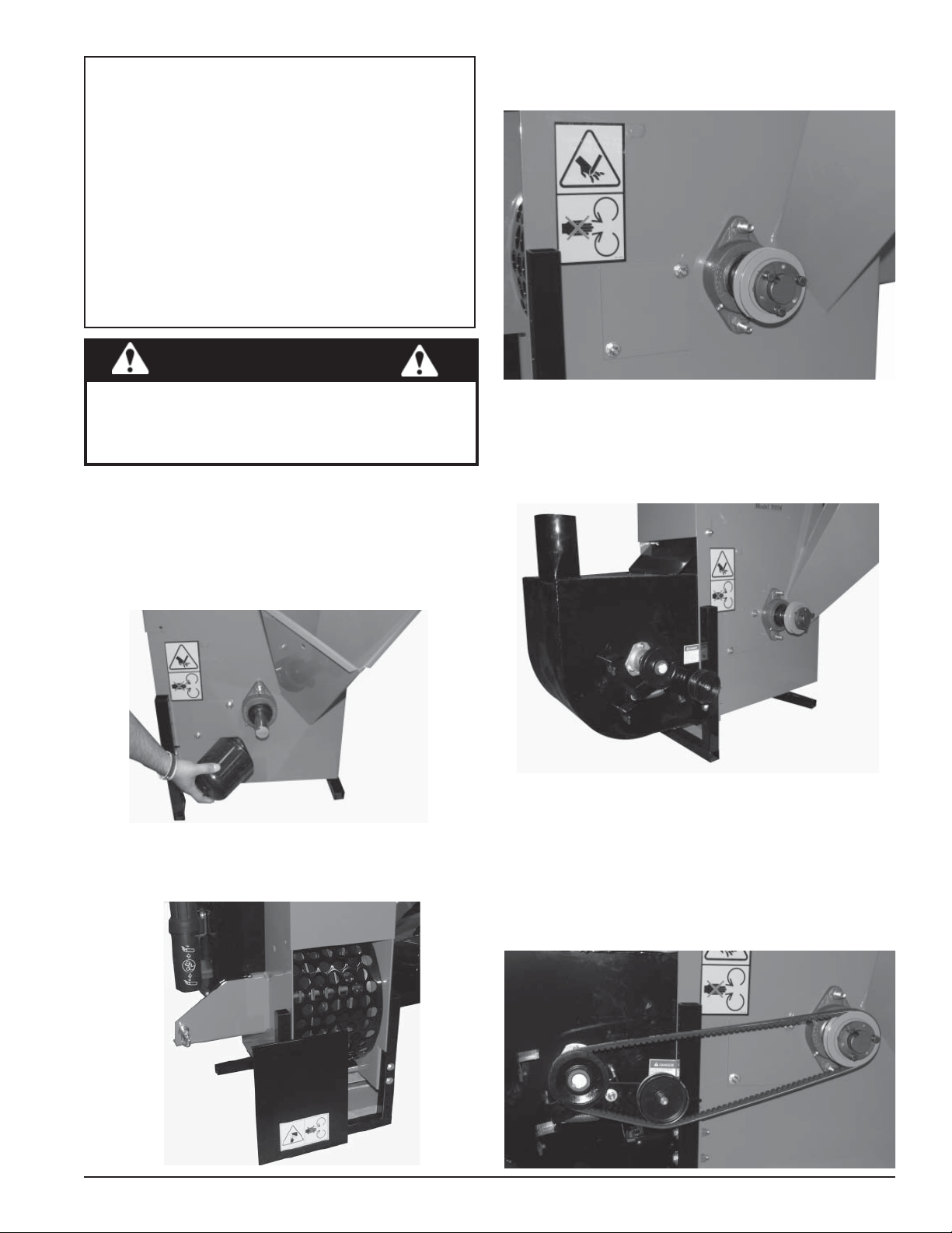
ASSEMBLY
Remove the rotor shaft end cap from the chipper.1.
Remove one (1) 5/16 lock nut from discharge door 2.
rod, pull out rod and remove discharge door.
Hold blower assembly up to frame, install new rod into 4.
frame and blower assembly and secure with 5/16"
lock nuts from kit. Slide bottom end of blower until it
fits against frame assembly . Make sure to hook the lip
of the blower to the lip on the chipper bottom.
Install belt onto the pulley that was just installed and 5.
onto the pulley on the blower assembly. The idler
pulley should run on the inside of the belt for correct
tension. Align pulleys to within 1/16".
Tighten bushing bolts in a clockwise direction and 6.
bushing set screw on rotor shaft pulley. Torque to
manufacturer's specifications.
Instruction Sheet
PN 16087
Rev. 050409
Page 2
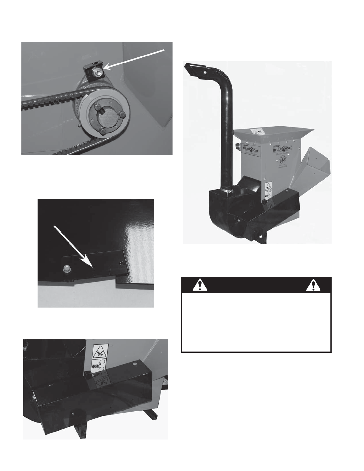
Install belt guard support bracket onto top 1/2" bolt for 7.
bearing on main frame and secure with 1/2" lock nut.
If you are installing the blower on the PTO chipper, 8.
remove the two small plates from the belt guard to
allow the guard to fit around the legs of the chipper
Install blower deflector on the blower tube with two (2) 10.
5/16" x 3/4" carriage bolts, one locknut and one spout
knob. Install the blower tube onto the blower assembly
and secure with the clamp.
Install belt guard with four (4) 5/16" bolts and washers 9.
from the kit.
OPERATION
WARNING
Read and follow all safety instructions in your machine
owner's manual. Failure to operate the machine in
accordance with the safety instructions MAY RESULT
IN PERSONAL INJURY!
Before inspecting or servicing any part of this machine,
shut off power source and make sure all moving parts
have come to a complete stop.
Test run the machine after installing the blower and 1.
check the belt guard to make sure the belts do not
rub, adjust if needed. Check bolt torque after a few
hours of use.
Feed materials slowly into the chipper and shredder 2.
chutes to get used to the rate of discharge. The
machine may discharge materials slightly slower with
the blower and discharge tube installed.
To rotate the blower discharge tube, loosen the clamp 3.
around the base of the tube, reposition the tube, and
tighten the clamp.
Instruction Sheet
Page 3

29
12
10
37
30
17
40
4
19
16
11
38
25
28
32
24
6
33
22
35
13
REMOVE
FOR PTO
MODEL
34
7
36
8
9
3
5
31
26
21
27
39
2
20
15
1
23
14
18
SINGLE SPEED COMMERCIAL BLOWER, PN 70487
ITEM PART NO. DESCRIPTION QTY
1 12174
2 15003 BOLT, 5/16 X 3/4 HEX HD 7
3 15008
4 15049 NUT, 1/2 CENTERLOCK 1
5 15097 WASHER, 1/2 FLAT 1
6 15140 BOLT, 5/16 X 2 HEX HD 4
7 15178 NUT, 5/16 CENTERLOCK 3
8 15219 BOLT, 5/16 X 1 HEX HD 1
9 15250 WASHER, 5/16 FLAT 11
10 15321 KNOB, SPOUT 5/16-18 1
11 15356 NUT, 5/16 NYLOCK 13
12 15367 BO LT, 5/16 X 3/4 CRG GR5 ZP 2
13 15388 NUT, 3/8 NYLOCK 1
14 15391 KEY, 1/4 X 2 SQUARE 1
15 15402
16 15422
17 16016 BUSHING, SH 1-1/2 IN 1
18 16086 V-BELT, BX-49 1
19 16499 SHEAVE, 1B 3.6 SH 1
DECAL, SHIELD DANGER
ISO
BOLT, 3/8 NC X 2 HEX HD
GR5
NUT, 5/16 TINNERMAN
U-TYPE
SCREW, TEK HX WSH HD
10/16 X 1 ZP
1
1
4
4
20 17692 SPRING, BLOWER DRIVE 1
21 17740 PULLEY, 3-1/2 IDLER 1
22 17831 BEARING, 1 IN FLUSHMOUNT 2
23 17958
24 17960 CLAMP, T-BOLT 4-1/4 ID ZP 1
25 36176-00 DECAL, INSTRUCTION ISO 1
26 41158 TUBE, SPACER 1
27 69126 SPACER, IDLER PIVOT 1
28 70249 BLOWER TUBE 1
29 70253 SPOUT, BLOWER TUBE 1
30 70471
31 70475 IDLER PLATE, BLOWER 1
32 70478 SHAFT, LARGE BLOWER 1
33 70481
34 70485 WELDMENT, BELT GUARD 1
35 70486
36 70495 SPACER, .54 X .88 3
37 70521 PIN, 5/16 X 14 1
38 70760 CA P, R O T O R SHAFT END CAP 1
39 71385 COVER, ACCESS 1
40 70496 BRACKET, BELT GUARD 1
PULLEY, (CAST) 4.0 X 1.0
B-GROOVE
WELDMENT, LARGE
BLOWER IMPELLER
WELDMENT, LARGE
BLOWER
REMOVABLE SHIELD, BELT
GUARD
1
1
1
2
Instruction Sheet
Page 4

UNPLUGGING THE BLOWER
If the machine plugs, turn off the power source and 1.
make sure all moving parts have come to a complete
stop.
Remove the access cover (shown at right) and carefully 2.
clear out the debris.
If necessary, remove blower discharge tube and clear 3.
debris from tube.
Bolt access cover back in place.4.
ACCESS
COVER
Test the machine.5.
Remove access cover if machine plugs
SAFETY DECALS
The blower comes with the safety decals pictured below. Familiarize yourself with all of the safety and operating decals
on the machine and the associated hazards. Make certain that all safety and operational decals on this machine are
kept clean and in good condition. Decals that need replacement must be applied to their original locations.
PN 12174
PN 12174
DO NOT OPERATE MACHINE
WITHOUT SHIELDS IN PLACE.
FAILURE TO DO SO MAY CAUSE
SERIOUS INJURY OR DEATH.
Keep these instructions with your chipper/shredder
owner's manual as a reference.
DO NOT REMOVE CLEANOUT ACCESS COVER
UNLESS MACHINE IS STOPPED AND SPARK
PLUG WIRE OR DRIVE SHAFT IS DISCONNECTED. USE ACCESS FOR CLEANOUT OR
INSPECTION ONLY. DO NOT OPERATE MACHINE WITH ACCESS COVER REMOVED.
IMPORTANT
PN 36176-00
CRARY INDUSTRIES
237 NW 12th Street, West Fargo, ND 58078-0849
Phone: 701.282.5520 • Toll Free: 800.247.7335
Fax: 701.282.9522
E-mail: service@crary.com • opesales@crary.com
www.BearCatProducts.com
 Loading...