

Page 1
OPERATING INSTRUCTIONS
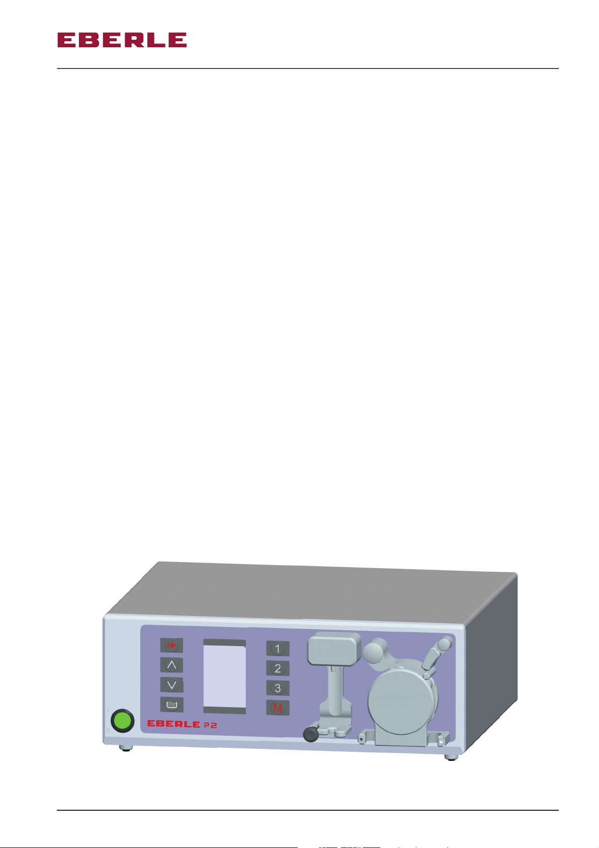
Arthroscopy Pump P2
EBERLE Arthroscopy Pump P2 913031
Page 2
OPERATING INSTRUCTIONS
Arthroscopy Pump P2
1 4 5
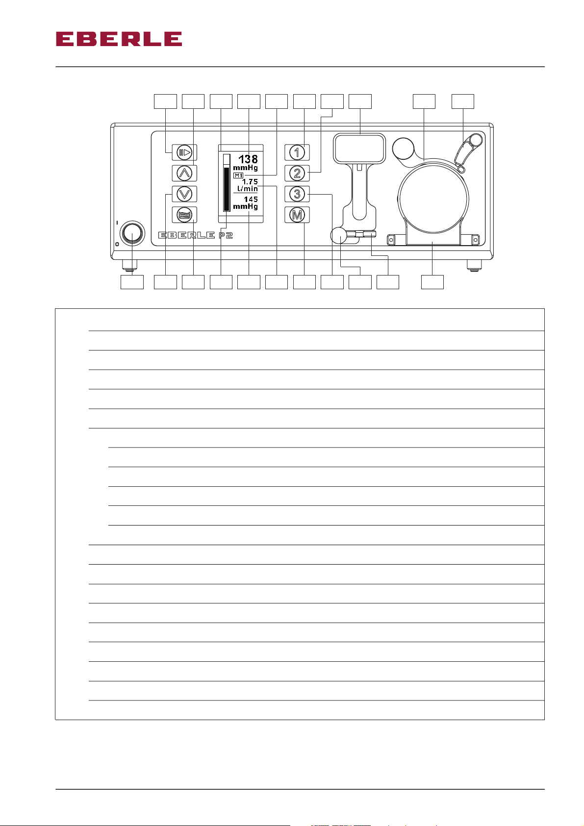
Power switch1
Start/stop key2
Key for pressure increase3
Key for pressure decrease4
2 3 76
6a 6e 6d
10 9
11 15
12 13 16
146b 6c 8
Key for filling5
LCD display6
6a Graphic pressure display
6b
6c
6d
6e
Current pressure
Display of selected memory location
Display of maximum delivery volume
Display of set pressure
Key for call of storage on memory location 17
Key for call of storage on memory location 28
Key for call of storage on memory location 39
Memory key10
Pressure transducer retainer11
Release button12
Locking tab13
Clamping bracket14
Locking lever15
Tube holder16
K1Brief description
Page 3
OPERATING INSTRUCTIONS
Arthroscopy Pump P2
17
19 18
222120
18b18a
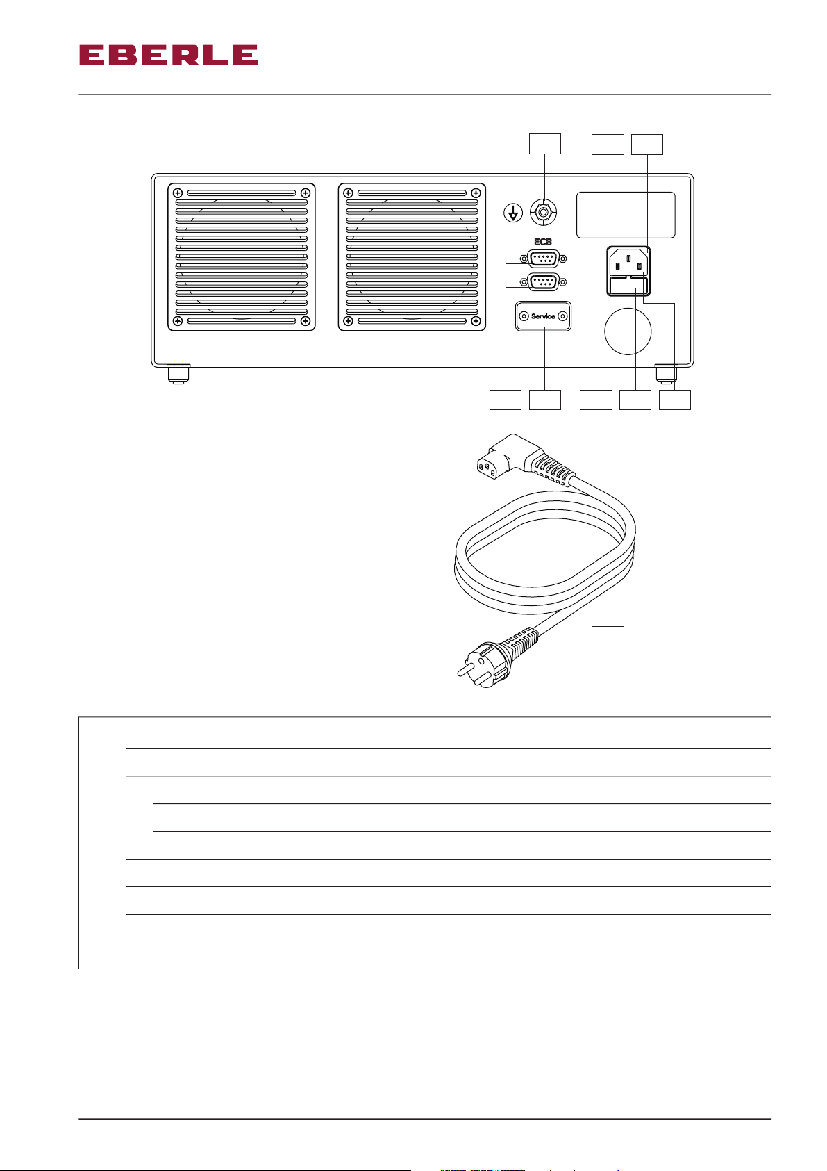
Equipotential bonding17
Power connector18
18a Mains fuse box with fuse holder
18b
Connector for power plug
Type plate19
ECB (external communication)20
Service port21
Certification label22
Mains power cable23
23
K2Brief description
Page 4
OPERATING INSTRUCTIONS
Arthroscopy Pump P2
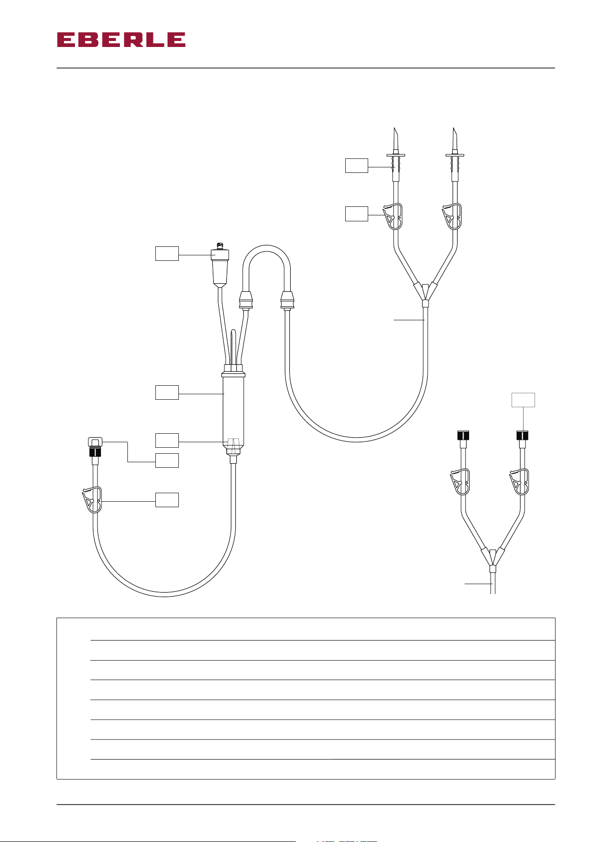
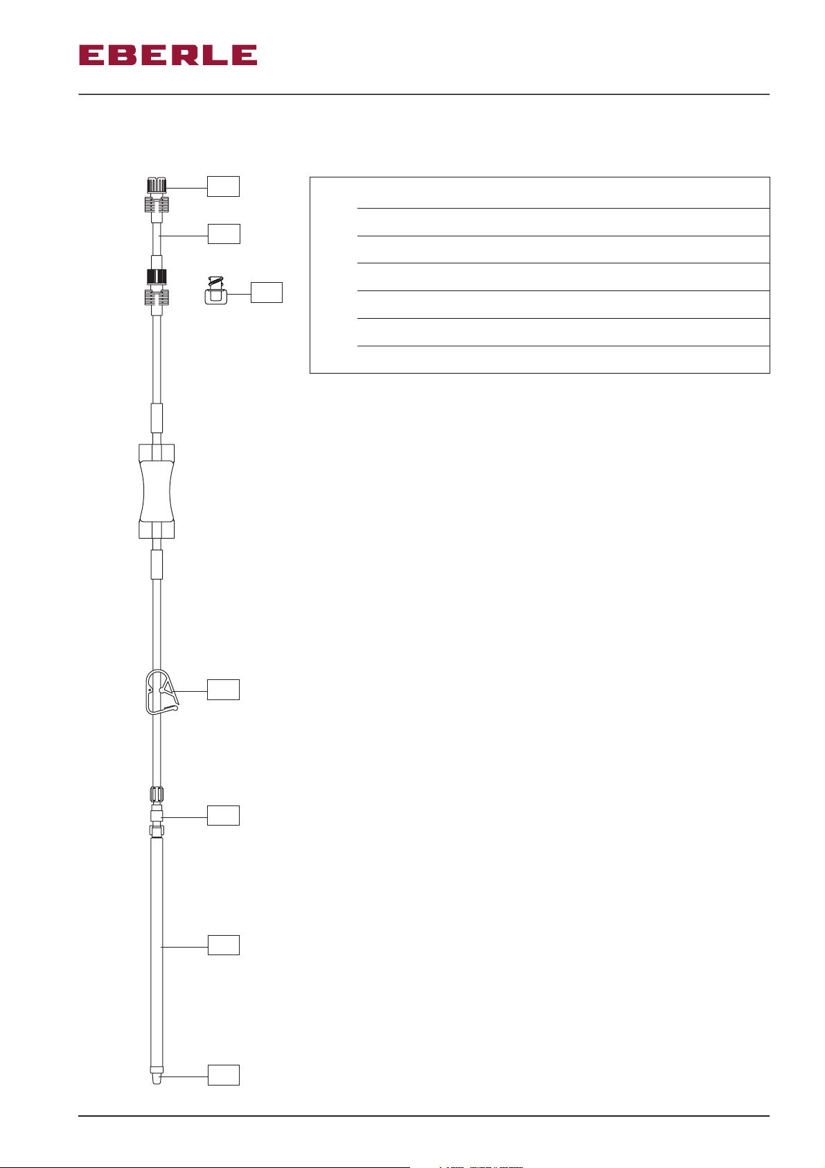
Tube-Set for Arthroscopy (art. no. 900154 and art. no. 900155)
24
26
27
900154
28
29
31
30
900155
Bleeder pin art. no. 90015424
Luer-lock art. no. 90015525
Tube clamp26
25
Pressure transducer27
Reservoir28
Filter screen29
Tube clamp30
White Sealing cap31
K3Brief description
Page 5
OPERATING INSTRUCTIONS
Patient-Tube with Luer-Lock (art. no. 900153)
Arthroscopy Pump P2
32
33
38
36
Blue sealing cap32
Sterile buffer zone33
Tube clamp34
Luer-connector35
Highly flexible end tube
End cap37
Sealing cap38
34
35
36
37
Brief description
K4
Page 6

Contents
OPERATING INSTRUCTIONS
Arthroscopy Pump P2
Page
1.
2.
3.
3.1
4.
4.1
4.2
4.3
4.4
4.5
5.
5.1
5.2
5.3 Contrast Setting 9
5.4 Connectors / Ports 10
General Information, description and field of application
Scope of Delivery
Symbol definitions
Safety Instructions and Warnings
Connection and Start-Up of Device
Inserting the Tube-Set and the Complete-Set for Arthroscopy
(art. no. 900154,900155, 900209 and art. no. 900210)
4.1.1
4.1.2
4.2.1
Leakage Checks of Tube-Set and the Complete-Set for
Arthroscopy
Filling of Tube-Set and the Complete-Set for Arthroscopy
Connecting of Patient End-Tube with Luer-Lock (art. no. 900153)
Filling of Patient End-Tube with Luer-Lock
After Surgery
Preparing of Next Surgery
After Last Surgery of the Day
Operating
Key assignment
Setting of Maximum Flow Rate
1
1
2
3
4
4
5
5
5
6
6
6
7
8
9
9
6.
7.
7.1
8.
9.
9.1
9.2 Factory Settings
10.
11.
12.
13.
Device-specific Symbols
Preparing of Device and Accessories
Cleaning of Device
Service, Maintenance, Inspection and Disposa
Trouble Shooting
Software version
Technical data
Compatibility
Warranty
Addresses
10
11
11
11
12
12
12
13
14
14
15
Contents
Page 7
OPERATING INSTRUCTIONS
Arthroscopy Pump P2
1. General Information, description and field of application
The EBERLE arthroscopy pump P2 was developed for surgical use in the field of arthroscopy.
The device assures a continouos flow of the flush medium by permanently monitoring and
controlling pressure.
The arthroscopy pump P2 should only be used by trained personnel in designated
!
medical institutions.
The EBERLE arthroscopy pump P2 is intended for use in arthroscopic joint surgery of knee,
shoulder, elbow, wrist or ankle. Use in other areas is prohibited!
Before operating the pump, please read these instructions carefully. They contain all
necessary information to ensure an appropriate connection and operation of the device.
Additionally, important safety and cleaning information is explained.
Keep these operating instructions in a safe and easily accessible place for future reference.
Utilizing or operating the device in non-conformance to these operating
!
instructions can injure the patient and /or the operating personnel and damage the
pump!
We thank you for your confidence and wish you much success with the EBERLE arthroscopypump P2!
2. Scope of Delivery
After delivery of the arthroscopy-pump, at first the packaging should be checked for external
damage.
The delivery of the arthroscopy-pump (art. no. 913031) includes the following items:
Arthroscopy pump P2
1
Mains power cable 1,8m [23]
1
Operating instructions P2
Should one or several components be damaged or found to be missing, please immediately
contact an EBERLE representative or an authorized service or distribution center.
article no. 913031
article no. 913035
1
Page 8

3. Symbol definitions
OPERATING INSTRUCTIONS
Arthroscopy Pump P2
!
observed.
Circular icons with a diagonal bar indicate actions that are prohibited.
This symbol alerts the user to an information that must be observed. Failure to
Triangular icons advise the user to important information that must be
!
observe this information can result in patient or user injury and / or damage the
unit.
This symbol alerts the user to follow the operating instructions.
This symbol on the packaging, instruction manuals, and / or the device indicates
that this product shall not be treated as consumer waste. The correct disposal
will help to prevent health or environmental impacts.
This symbol indicates a device with one or more applied parts of Type B
This symbol indicates a device with one or more applied parts of Type BF
XX
XXXX-YY
PHT
XX
DEHP
This symbol on the packaging indicates the upper and lower storage
temperature for the device.
This circular symbol indicates that products with damaged packaging must not
be used.
This symbol in conjunction with a date e.g. 2007-06, shows the usability of the
product until the specified date.
This symbol identifies products that have been sterilized in the final packaging
and additional the sterilization process, in the illustrated case, the sterilization
with ethylene oxide.
This circular symbol identifies products that are approved for single use only and
may not be reused.
This symbol identifies products that contain phthalates in the form of di-2ethylhexyl phthalate.
2
Page 9

3.1 Safety Instructions and Warnings
Utilizing or operating the device in non-conformance to these operating
!
instructions can injure the patient and /or the operating personnel and damage the
pump!
OPERATING INSTRUCTIONS
Arthroscopy Pump P2
All Tube sets are singel use products and must not be reused
Damaged or defective hose systems are no longer to be used and replaced
immediately!
The electrical installation of the operation room must adhere to the requirements of
!
the applying IEC standards and national regulations! The device is only reliably
grounded, if the device is connected to a ground-type receptacle. Routinely check
the plug and the cable and do not use if damaged.
The pump may only be switched on, once all connecting cables are completely
connected. Prior to every application check the device with regard to possible
damages and operational capability!
Mobile HF communication devices such as mobile phones can influence electrical
medical equipment! Do not operate such communication devices close to electrical
medical devices!
Position the pump out of the reach of the patient on a secure support.
Where possible, the pump should be placed at the level of the surgical area for a
precise pressure measurement!
Pay attention to the permissible environmental conditions!
Do not operatet the device in harzardous areas. Using ignitable anesthetic gas in
the near vicinity of the pump increases the risk of explosion.
!
The device must be disconnected from the mains prior to any kind of maintenance,
!
cleaning and disinfection procedures. The external surfaces of the pump can be
cleaned with a disinfectant and cleaning agent that preserves the paint. Attention
must be paid that no liquid enters the device!
Do not open the device! Risk of electric shock! Arbitrary opening, repairing or
modifying of the device absolves us from any liability regarding the operational
safety of the device and results in expiry of any claims whatsoever during the
period of warranty
Using non-compatible foreign auxiliaries can result in the patient and/or the
operator being endangered or injured!
!
Ensure sufficient aeration at the vents on the rear of the device. Insufficient
aeration results in damage or malfunction!
In case of failure (e.g. overvoltage) a replacement device or an alternative
supply is to keep ready.
Avoid contact with moving parts.
3
Page 10

OPERATING INSTRUCTIONS
Arthroscopy Pump P2
4. Connection and Start-Up of Device
All components should again be checked visually for any signs of damage before connecting
the device and starting it up.
A damaged packaging can lead to unsterile or damaged parts. Damaged parts and
parts from damaged sterile packaging must not be used and replaced immediately!
The sequence shown below must always be observed for connection and start-up.
!
Please follow the steps described below:
Switch off power switch [1] at the front panel of the pump (position 0)
-
Insert the mains power cable [23] into the connector [18] at the back of the device,
-
now connect to mains.
Establish equipotential bonding [17] (where required, by skilled personnel)
-
Switch on power switch [1] at the front of the pump (position I) and check the
-
operational controls for correct functioning.
4.1. Inserting the Tube-Set and the Complete-Set for Arthroscopy
(art. no. 900154, 900155, 900209 and )art. no. 900210
If applicable, open locking lever [15] by turning it clockwise
-
If applicable, fold in the clamping bracket [14] anticlockwise
-
Remove tube-set (art. no. 900154 or art. no. 900155) from the sterile packaging
-
Insert the Luer connection of the pressure transducer [27] into the cone of the pressure
-
transducer retainer [11]. If necessary solve the locking tab [13] by pressing the release
button [12], then close the locking tab [13] completely.
Insert the black tapper of the tube from below into the therefore provided opening
-
(marked with a black dot) of the tube holder [16]
Place the tube in the middle round the pump roller and then pull it downwards through
-
the opening marked white
Let the tube relax and slide the white tapper from below into the therefore provided
-
opening
Check the position of the tube (the tube must be in the middle of the clamp roller)
-
and, if required, correct the position of the tube in the area of the pump rollers.
-
Fold in the clamping bracket [14] clockwise
-
Turn the locking lever [15] anticlockwise until it clicks into place in the clamping bracket
-
[14]
Press the patient end of the day's tube-set or the complete-set into the notch on the
-
side of the pressure transducer retainer [11]
4
Page 11

OPERATING INSTRUCTIONS
Arthroscopy Pump P2
4.1.1. Leakage Checks of Tube-Sets for Arthroscopyand the Complete-Set
If applicable, close the tube-set for arthroscopy on the patient side
-
(delivery status)
Switch the pump on by means of the power switch [1], set a pressure greater 100
-
mmHg and then press the start/stop key [2]
Check the set value, if the value does not change for about 1 minute or if it increases,
-
terminate the standard operation by pressing the start/stop key [2] again
If the value decreases during this minute, verify that the pressure transducer [27] has
-
been assembled correctly or check the clamp on the patient-side of the tube Hence
check if the set value decreases again. If the value now does not decrease for 1 minute,
terminate the standard operation by pressing the start/stop key [2]
Should these measures be ineffective, terminate the standard operation by pressing
-
the start/stop key [2] and check the center position of the tube in the area of the pump
rollers. Thereafter start the leakage check once again.
or the complete-set
4.1.2. Filling of Tube-Set for Arthroscopyand the Complete-Set
The reservoir [28] must always hang vertically underneath the pressure transducer
!
[27], a horizontal position results in the pressure transducer [27] being filled and
can damage the pump.
Fasten at least one bag of infusion solution to the inflow (Y-port) of the tube-set
-
complete-set
bag is used, close the tube clamp [26] on the not used inflow.
Now press the filling key [5] (flashing key) until the lower part of the reservoir [28]
--
is filled with infusion solution (at the maximum up to the top edge of the filter screen
[29])
Should too much solution have entered the reservoir [28], open the sealing cap [31] on
-
the patient side until the filling level has settled in the region of the filter screen [29].
Close the tube clamp [30] on the patient side.
-
for arthroscopy and open the corresponding tube clamp [26]. If only one
4.2. Connecting of Patient End-Tube with Luer-Lock (art. no. 900153)
The sterile person removes the patient end-tube with Luer-lock from the sterile
-
packaging (leaving the sterile-packed sealing cap [38] in the packaging), checks the
screw fittings and hands over the end with blue sealing cap [32] (sterile buffer zone
[33]) to the non-sterile person.
The non-sterile person removes the blue sealing cap [32] at the patient end-tube with
-
Luer-lock as well as the white sealing cap [31] at the tube-set for arthroscopy and
connects both tubes with each other.
or the
5
Page 12

OPERATING INSTRUCTIONS
Arthroscopy Pump P2
The sterile person removes the end cap [37] or the highly-flexible end-tube [36] at the
-
still remaining end and connects these with the tube clip or the Luer-connector. The
highly-flexible end tube [36] must be removed before connecting the Luer-connector of
the arthroscopy shaft.
The sterile person hands over the sterile packing, with the sealing cap [38] still inside,
-
to the non-sterile person Store the sealing cap [38] in a safe place since it will be
needed at the end of the surgery.!
The complete-cets art. no. 900209 and art. no. 900210 are designed for single use
!
and are shipped with a permamently attached end-tube. A change of the Patient
end-tube is not possible in this set.
4.2.1. Filling of Patient End-Tube with Luer-Lock
Set the required pressure and start the pump by pressing the start/stop key [2]
-
Open the stop cock on the arthroscopy shaft.
-
Open the tube clamp [30] between the sterile buffer zone [33] and the reservoir [28].
-
After the filling, close the stop cock on the arthroscopy shaft.
-
The pump is now ready for operation!
4.3. After Surgery
Close the tube clamp [30] between the reservoir [28] and the sterile buffer zone [33].
-
Stop the pump by pressing the start/stop key [2]
-
Open the sterile packaging of the sealing cap [38] (from sterile packaging of patient
-
tube-set)
Detach the tube connection at the second blue Luer-lock connector and immediately
-
close it with the sealing cap [38], the short piece of the tube remains at the day's set
until the next surgery.
4.4. Preparing of Next Surgery
The sterile person removes the patient end-tube with Luer-lock (art. no. 900153) from
-
the sterile packaging, leaving the sterile-packed sealing cap [38] in the packaging,
checks the screw fittings and hands over the end of the sterile buffer zone [33] with the
blue sealing cap [32] to the non-sterile person.
The non-sterile person removes the blue sealing cap [32] at the patient end-tube with
-
Luer-lock and the short piece of tube (sterile buffer zone [33]) with the blue Luer-lock at
the tube-set for arthroscopy and immediately connects the two tubes with one another.
Two sterile buffer zones may never be connected to one another
6
Page 13

OPERATING INSTRUCTIONS
Arthroscopy Pump P2
The sterile person removes the end cap [37] or the highly-flexible end tube [36] at the
-
remaining end and connects these with the tube clip or the Luer-connector of the
arthroscopy shaft (for connection to the Luer-connector, the highly-flexible end tube
[36] must be removed).
The sterile person hands over the sterile packing, with the sealing cap [38] still inside,
-
to the non-sterile person. Store the sealing cap [38] in a safe place since it will be
needed at the end of the surgery!
Now fill the patient tube-set as described in Filling of Patient End-Tube with Luer-Lock
-
4.5. After Last Surgery of the Day
Close all tube clamps
-
Switch off pump with the power switch [1]
-
For removal the pressure transducer [27] press the release button [12] and release
-
until the locking tab [13] is dissolved. Remove the pressure transducer [27] with a
slight pull at simultaneously rotating down.
Dispose of all tubes
-
7
Page 14

5. Operating
OPERATING INSTRUCTIONS
Arthroscopy Pump P2
2 3 76
1 4 5
6a 6e 6d
10 9
11 15
12 13 16
17
146b 6c 8
19 18
222120
23
18b18a
8
Page 15

OPERATING INSTRUCTIONS
Arthroscopy Pump P2
5.1 Key assignment
Power switch [1]
Switch on the device by pressing the power button.
The power switch has two positions:
l ON switched
O OFF off
If the device is switched on a green indicator light illuminated in the switch.
Start/Stop key [2]
Use this key to start (acoustic signal 1x) or stop (acoustic signal 2x) the pumping process.
During operation, the illumination of the key flashes to indicate an activated pump function.
Key for pressure increase/decrease [3-4]
Use these key to change pressure.
To adjust the pressure, press the keys [3] und [4] until the required pressure is
reached.
For safety reasons, the pressure increase above 120 mmHg will be interrupted every 5
mmHg, further pressure increase is only possible after releasing the key for pressure
increase [3].
Key for filling [5]
Use this key to fill the Tube-Set as described in Filling the Tube-Set and the Complete-Set for
Arthroscopy.
Memory key [10], Key for call of storage on memory [7-9]
These keys can be used to retrieve and store the application data such as flow and pressure
settings.
The stored values can be called by means of the keys [7], [8] or [9]. By means
of these keys it is possible to assign up to 3 memory locations depending on the application
(e.g. knee with tourniquet, hip, shoulder). For safety reasons, it is not possible to change
between memory locations during standard operation.
To save the values, press key [10] for approx. 1 second until the memory location [6c]
flashes in the display. The confirmation of the saved value flashes until the key is released.
The values are saved to the set memory area.
A storing of values above 120 mmHg is not possible for safety reasons.
5.2 Setting of Maximum Flow Rate
To set the maximum flow rate, press key [8] during standard (Flashing key [2])
operation and adjust the desired value by means of keys [3] and [4].
5.3 Contrast Setting
To set the contrast of the display press key [7] and keep it pressed while adjusting the
desired contrast value by means of the keys [3] and [4].
9
Page 16

OPERATING INSTRUCTIONS
Arthroscopy Pump P2
5.4 Connectors/Ports
Pressure transducer retainer [11], Tube connector unit [14/15/16]
Connector to mount and control the Tube-Set and the Complete-Set for Arthroscopy.
Equipotential bonding [17]
Generally, the control unit is earthed by the 3-pin safety plug, if it is connected – as stipulated
- to an earthed power cable. When this device is operated in rooms of application group 2
according to DIN VDE 0107 it is indispensable that the device is connected to the stationary
equipotential bonding of the room or of the medical device cart by a corresponding cable. The
device has an according plug connector for this (according to DIN 42801).
Power connector [18]
The plug of the power cable is connected to this inlet connector for non-heating apparatus
[18]. Only use the delivered mains power cable [23]. The fuses of the device are located in
the fuse holder [18a]. Please only use the fuse types that are mentioned on the type plate
[19]! How to exchange the fuses is explained in the service chapter of these operating
instructions.
ECB [20]
Coded connection (Eberle Comunication BUS)
The ECB port is used for the mutual control of Eberle devices. Only use EBERLE
!
approved equipment and connecting cables for connection to the ECB.
To avoid hazards never touch simultaneously the ECB port and the patient.
Service Port [21]
Service and diagnostic port
The service port is for diagnostics, and may be used only by authorized personnel
!
and for service purposes only.
6. Device-specific Symbols
Start/Stopp [2]
Pressure increase [3]
Pressure decrease [4]
Filling [5]
Memory key [10]
Power switch on [1]
I
Power switch off [1]
0
Potential equalization connection
10
Page 17

OPERATING INSTRUCTIONS
Arthroscopy Pump P2
7. Preparing of Device and Accessories
The device and the accessories must be decontaminated prior to the first and to any
subsequent use. The cleaning and sterilization methods apply that are given in the
instructions that are included in the delivery of the device or of the accessories or of any other
item. This does not apply to accordingly marked, sterile-packed disposable articles.
Insufficient cleaning and/or sterilization can result in infection of the patient and/or the
operator.
The operator is responsible for the validation of the cleaning and sterilization processes.
7.1. Cleaning of Device
The external surfaces of the device can be cleaned with a disinfectant and cleaning agent that
preserves the paint.
The device must be disconnected from the mains prior to any kind of cleaning and
!
disinfecting procedures!
Attention must be paid that no liquid enters the device during cleaning!
8. Service, Maintenance, Inspection and Disposal
Defective devices may only be repaired by authorized experts and only by using
!
original parts.
Replacing of the mains fuse can be performed as described below by local qualified
personnel:
Switch off power switch [1] at the front of the device (position )O
-
Disconnect power plug [23] and equipotential bonding [17] from the device
-
With a flathead screwdriver or any other suitable tool lift the fuse holder out of the
-
mains-fuse box [18a]
Take out defective fuses and insert new fuses according to type plate [19]
-
Insert fuse holder into mains-fuse box [18a]
-
Connect power plug [23] and equipotential bonding [17]
-
Switch on power switch [1] (position )I
-
Regular servicing can help to detect defects and malfunctions at an early stage and thereby
possibly extend the service life of the device. Nevertheless, servicing is not mandatory.
Independent of the country-specific safety regulations (e.g. accident prevention regulation,
inspection interval regulation), we recommend yearly function and safety checks according
to VDE 751 by an authorized service center. This check should be displayed on the device by
means of a sticker. National regulations must be observed, should disposal of the device
become necessary.
11
Page 18

9. Trouble Shooting
OPERATING INSTRUCTIONS
Arthroscopy Pump P2
Symptom
Complete failure of device
- out of operation
- power switch on
- power switch lamp is off
Pump causes irregular - filter in the pressure - replace day's tube-set
pressure fluctuations transducer is wet [27] is
Too high filling level in the - leakage - check if pressure
Pump does not reach the set - set flow rate too low - increase max. flow rate
pressure icht
Display can hardly be read or - set contrast too high/low - adjust contrast as
not at all
Possible Cause
- power supply failed - check power supply
- mains fuse defective - replace fuse on device
wet
Remedy
transducer [27] isreservoir [28]
assembled correctly and
if all connections on the
rinsing tube are closed.
If required, replace the
entire tube system
described in the chapter
contrast setting
- restart the device
9.1. Software Version
After switching on the device, the software version (e.g. 2.00) is displayed for about 2
seconds.
9.2. Factory Settings
To delete the custom settings you can activate the factory default settings with a software
reset.
Turn the power switch [1] off (position ). Now press simultaneously [3] and the [4]
key, keep it pressed and switch on the device. Hold the keys down until the message
" " appears.
Settings loaded
Did the first factory reset fail, rerun the software reset. Should this not be successful, please
contact the service.
0
12
Page 19

10. Technical Data
OPERATING INSTRUCTIONS
Arthroscopy Pump P2
Safety classification,
IEC 601-1
Classification MDD
93/42/EEC
Electrical data Supply voltage
Possible EM- or other
disturbances
IP-Code
Pressure ranges
Pressure flow
Environmental conditions
Protective class
Application part
Risk class IIa
Mains frequency
Mains fuse
Max. power input
Emitted interference .
solid particle protection
liquid ingress protection
Pressure 0-200 mmHg
Flow rate 0-1750 ml/min
Temperature
Relative humidity
maximum altitude
minimum atmospheric
pressure
I
Typ BF
100-240 V/AC
50/60 Hz
2xT1AH250V
100 VA
IP30
15 to 30°C
30-75% not condensed
2000m
795hPa
Storage and
transportation conditions
Mechanical data
Accessories Tube-set for arthroscopy with bleeder pin
Temperature
Relative humidity
Dimensions: L/W/H in mm
Weight
Tube-set for arthroscopy with Luer-connector
Patient tube-set
Complete Set for arthroscopy with piercing canulla
Complete Set for arthroscopy with scope
-10 to 70°C
30-75% not condensed
300x350x125mm
7800g
13
Page 20

OPERATING INSTRUCTIONS
Arthroscopy Pump P2
11. Compatibility
When operating the EBERLE pump P2 only use the EBERLE components listed in the table
below!
Aarticle no.
900153
900154
900155
900209
900210
913035 Mains power cable 1,8m
913036
Future EBERLE products can also be compatible. Detailed information regarding this can be
obtained from every EBERLE representative.
Using non-compatible foreign auxiliaries can result in the patient and/or the
!!
operator being endangered or injured!
Description
Patient end-tube with Luer-lock
Tube-set for arthroscopy with bleeder pin
Tube-set for arthroscopy with Luer-connector
Complete-set for arthroscopy with bleeder pin
Complete-set for arthroscopy with Luer-connector
ECB connecting cable 1,0m
12. Warranty
The warranty period for the EBERLE arthroscopy pump P2 is 12 months. Faults resulting
from faulty material and/or workmanship will be rectified free of charge by the manufacturer
during this warranty period
Transportation costs and shipping risks cannot be assumed by the manufacturer. Over and
above, the details apply that are stated in our General Terms and Conditions of Businesn..
Do not open device! Unauthorized opening, repairing and modifying the device
!!
results in immediate expiry of the warranty obligation and discharges us of any
liability regarding the operational safety!
14
Page 21

13. Addresses
Development, Production and Administration
Eberle GmbH & Co. KG
Glasbronnenstr. 6
75449 Wurmberg
T +49 (0) 7044-9611-0
F +49 (0) 7044-9611-11
info@eberle-med.com
www.eberle-med.com
Sales
Eberle GmbH & Co. KG
Carl-Peschken-Straße 5c
47441 Moers
T +49 (0) 2841-8870032
F +49 (0) 2841-8870037
vertrieb@eberle-med.com
www.eberle-med.com
OPERATING INSTRUCTIONS
Arthroscopy Pump P2
Operating instructions
Arthroscopy Pump P2
R05/130411
15
 Loading...