

Page 1
1. Funktion
a) Die Hygrostate der Typen HYG-E 6001, HYG-E
7001/7005, und HYG 4003 eignen sich für den
automatischen Betrieb einer Be- oder Entfeuchtungsanlage.
b) Der HYG-E 7001/7005 ist eine Kombination
Hygrostat und Raumtemperaturregler für den
Einsatz in Schwimmbäder etc.
2. Elektrischer Anschluß
Schließen Sie alle Leitungen genau nach dem
Schaltbild im Gehäusedeckel an.
Diese Geräte dürfen nur durch einen Fachmann gemäß dem
Schaltbild im Gehäusedeckel installiert werden. Dabei sind
die bestehenden Sicherheitsvorschriften zu beachten.
Ö
wird durch entsprechenden Einbau (nach VDE 0100)
und der Montage auf einen ebenen, nichtleitenden und
nichtbrennbaren Untergrund erfüllt.
Diese unabhängig montierbaren Geräte dienen zur
Regelung der Feuchte bzw. der Temperatur ausschließlich
in trockenen und geschlossenen Räumen mit üblicher
Umgebung. Außerdem sind sie gemäß VDE 0875 bzw EN
55014 funkentstört und arbeiten nach der Wirkungsweise
1C.
4. Technische Daten
Achtung: Über AC 24 V nur in trockenen Räumen! Räumen (max 95 %, nicht kondensierend)!
Nicht geeignet z.B. für Gärschränke oder ähnliche Einrichtungen.
HYG-E 7001 HYG-E 7005 HYG-E 6001 HYG 4003
Hygrostat
Einstellbereich 35–100 % r.F. 35–100 % r.F. 30–100 % r.F.
bei HYG 7005 unter d. Deckel
Schaltdifferenz ca. 4% ca. 4% ca. 5%
Betriebsspannung 24…230V AC 24…230V AC 24…230V AC
Schaltstrom 5 (0,2) A AC; 5 (0,2) A AC; 15 (2) A
55 W DC 55 W DC
Kontakt 1 Wechsler 1 Wechsler 1 Wechsler
Temperaturregler
Einstellbereich 10–35°C – –
Schalttemperatur-Differenz ca. 0,6 K – –
Betriebsspannung AC 24/230V – –
Schaltstrom Heizen 10 (4) A – –
Kühlen 5 (2) A – –
Kontakt 1 Wechsler – –
Thermische Rückführung serienmäßig – –
Schalter Netz Ein/Aus – –
HYG 7005 ohne Netzschalter
Schutzart IP 30 IP 30 IP 54
Umgebungstemperatur 0…55°C 0…55 °C 0…60°C
Kabellänge – – –
Zulässige Luftgeschwindigkeit – – 8 m/sec.
4. Specification
Attention: For more than AC 24 V only in dry rooms (max. 95% without condensation).
Not suitable e.g. for brew cabinets or similar equipment
HYG-E 7001 HYG-E 7005 HYG-E 6001 HYG 4003
Hygrostat
Setting range 35–100 % r.F. 35–100 % r.F. 30–100 % r.F.
HYG 7005 below cover
Switching diff. approx. 4% approx. 4% approx. 5%
Operating voltage 24…230V AC 24…230V AC 24…230V AC
Switching current 5 (0,2) A AC; 5 (0,2) A AC; 15 (2) A
55 W DC 55 W DC
Contact 1 c/o 1 c/o 1 c/ o
Thermostat
Setting range 10–35°C – –
Switching temp. diff. approx. 0,6 K – –
Operating voltage AC 24/230V – –
Switching current heating 10 (4) A – –
cooling 5 (2) A – –
Contact 1 c/o – –
Thermal feedback standard – –
Switch Mains ON/OFF – –
HYG 7005 without mains switch
Degree of protection IP 30 IP 30 IP 54
Ambient temperature 0…55°C 0…55 °C 0…60°C
Cable length – – –
Admissible air speed – – 8m/sec.
3. Montage
HYG-E 7001/7005, HYG-E 6001
– Es ist darauf zu achten, daß die Geräte nicht
einer direkten Wassereinwirkung ausgesetzt
sind, z.B. Spritzwasser beim Schwimmbad usw.
– Der Hygrostat ist waagrecht, in Augenhöhe zu
montieren.
– Der Kabelaustritt aus der Wand ist bei den
Typen HYG-E 7001/7005, HYG-E 6001 unbedingt zu verputzen oder anderweitig, mit
Ausnahme von Silikon und silikonhaltigen
Materialien abzudichten.
HYG 4003
Der Hygrostat wird nach Möglichkeit im Abluftoder Umluftkanal vor dem Ventilator waagrecht
montiert. Max. zulässige Luftgeschwindigkeit
8 m/sec.
U 468 931022 899
Montage- und
Bedienungsanleitung
Hygrostate
1. Function
a) The HYG-E 6001, HYG-E 7001/7005 and HYG
4003 Hygrostats are suitable for the automatic
operation of a humidification and dehumidification equipment.
b) The HYG-E 7001/7005 is a combination of a
hygrostat and a room temperature controller for
use in swimming-pool halls, etc.
2. Electric supply
Connect all lines exactly according to the wiring
diagram shown in the case cover.
These units must be mounted by an expert, according to
the wiring diagram inside the housing cover. The existing
safety regulations must be observed.
Ö
Will be met by corresponding installation (acc. to VDE
0100) and by fitting on smooth and non-conductive
and non-flammable surface.
These units which can be mounted independently are for
controlling of humidity or ambient temperature in dry and
enclosed rooms only with normal environment.
They have radio interference suppression in accordance
with VDE 0875 or EN 55014 and operate to efficiency 1C.
3. Installation
HYG-E 7001/7005, HYG-E 6001
– Make sure the units are not exposed to direct
water effects, such as water jets in pool halls.
– Install the hygrostat in a horizontal position, at
the eye level.
– Plaster the spot where the cable leaves the
wall or seal otherwise when using the types
HYG-E 7001/7005, HYG-E 6001. Do not use
silicone or silicone-containing materials.
HYG 4003
Install the hygrostat in the foul air or recirculation duct after the fan, if possible. Max admissible air speed: 8 m/sec.
Installation and
Operating Instructions
Hygrostate
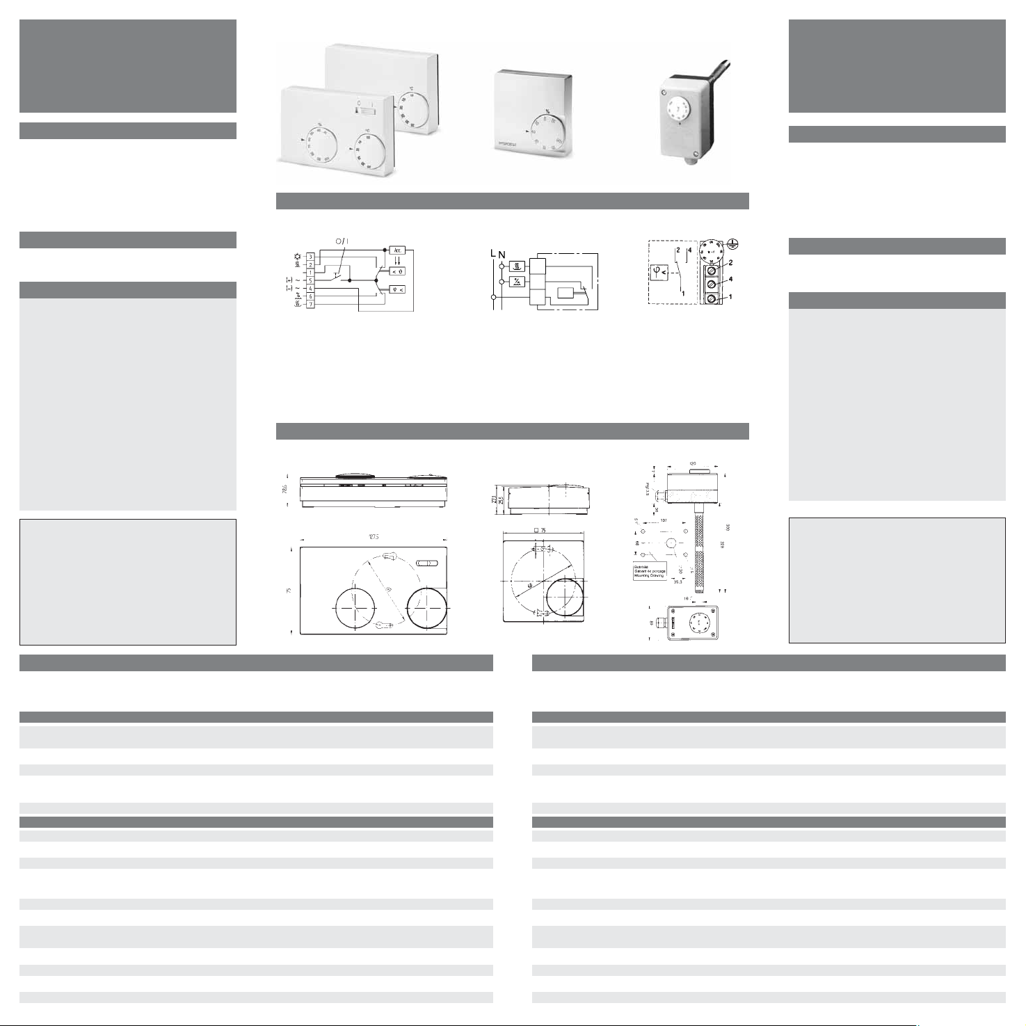
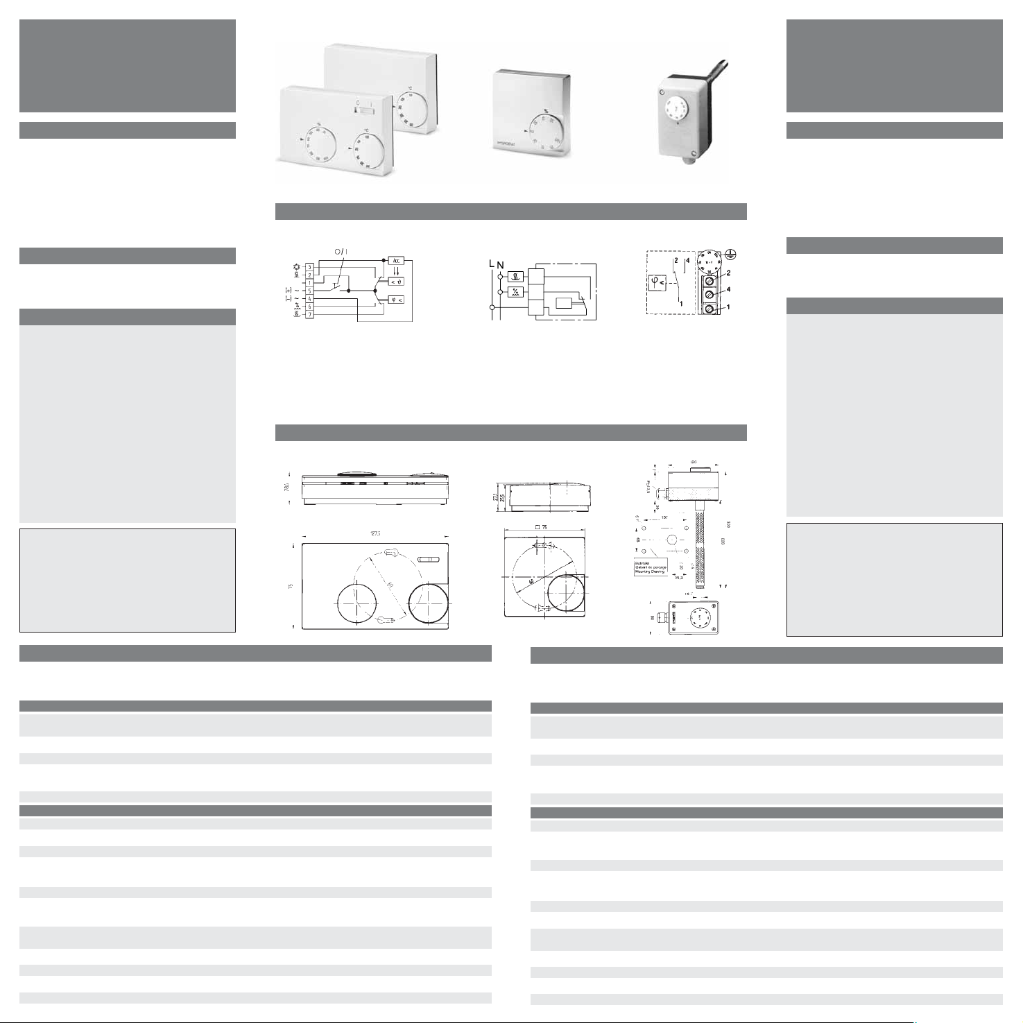
HYG-E 7001/ 7005 HYG-E 6001 HYG 4003
Schaltbild / Wiring Diagram
HYG-E 7001/ 7005 HYG-E 6001 HYG 4003
Maße / Dimensions
HYG-E 7001/ 7005 HYG-E 6001 HYG 4003
Klemme 1–4 Befeuchten
Klemme 1–2 Entfeuchten
terminal 1–4 humidify
terminal 1–2 dehumidify
Achtung: Über AC24 V nur in
trockenen Räumen!
Attention: For more than AC 24V only
in dry rooms!
Klemme 1–2 Entfeuchten
Klemme 1–3 Befeuchten
terminal 1–2 dehumidify
terminal 1–3 humidify
Hygrostat: Klemme 1/5–6 Befeuchten
Klemme 1/5–7 Entfeuchten
Temperaturregler: Klemme 1/5–2 Heizen
Klemme 1/5–3 Kühlen
Hygrostat: terminal 1/5–6 humidify
terminal 1/5–7 dehumidify
Temp. controller terminal 1/5–2 heating
terminal 1/5–3 cooling
Irrtum und Änderung vorbehalten
2
3
ϕ
>
1
Page 2
Ces appareils ne peuvent être installé que par un professionnel
selon le schéma à l’interiéur du couvercle et en respectant les
règles de l’art.
Ö
est garantit par un montage encastré conforme (VDE 0100)
et par un montage sur un fond plat, non conducteur et inin-
flammable.
Ces appareils qui peuvent être montés séparément sont faits
pour régler l’humidité et respectivement la température seulement dans des places sèches et fermées et avec l’ambiance usuelle. Ils sont construits et déparasités selon VDE 0875 et EN
55015 et leur manière d’opérer est selon 1C.
3. Montage
HYG-E 7001/7005, HYG-E 6001
– Ne pas exposer les appareils à des effets
d’eau directs, p.ex. aux projections dans
une piscine, etc.
– Monter le hygrostat en position horizonta-
le, à la hauteur des yeux.
– Crépir l’endroit oû le câble sort du mur ou le
rendre étanche en utilisant d’autres maté-
riaux, à exception de la silicone et des maté-
riaux siliconés, pour les types HYG-E
7001/7005 et HYG-E 6001.
HYG 4003
Monter l’hygrostat dans la gaine d’évacuation ou de reprise d’air, avant le ventilateur, si
possible. Vitesse maximale admissible:
8 m/sec.
U 468 931022 899
Instructions de montage
et de service pour
Hygrostats
1. Fonctions
a) La principale application des hygrostats des
types HYG-E 6001, 7001/7005 et HYG 4003
est dans le fonctionnement automatique d’une
installation d’humectation et de déshumectation.
b) Le HYG-E 7001/7005 est une combinaison
d’un hygrostat et d’un régulateur d’ambiance.
Parmi les applications typiques sont à noter les
piscines fermées.
2. Prise de courant
Raccorder toutes les lignes exactement d’après le
schéma des connexions se trouvant dans le couvercle du boîtier.
4. Caractéristiques générales
Attention: Ne pas utiliser dans des locaux humides au-dessus de 24 VAC (max. 95% sans condensation).
Utilisation déconseillée par ex. pour les armoires de brassage ou équipements similaires.
HYG-E 7001 HYG-E 7005 HYG-E 6001 HYG 4003
Hygrostat
Plage de réglage 35–100 % h.r. 35–100 % h.r. 30–100 % h.r.
HYG 7005 à l’intérieur du boîtier
Diff. de commutation env. 4% env. 4% env. 5 %
Tension d’alimentation 24… 230 V AC 24…230V AC 24…230V AC
Courant d’enclenchement 5 (0,2)A AC; 5 (0,2) A AC; 15 (2) A
55 W DC 55W DC
Contact 1 inverseur 1 inverseur 1 inverseur
Régulateur de température
Plage de réglage 10–35°C – –
Diff. de temp. de commutation env. 0,6 K – –
Tension d’alimentation AC 24/ 230V – –
Courant d’enclenchement Chauffer: 10 (4) A – –
Refroidir: 5 (2) A – –
Contact 1 rt – –
Réalimentation thermique en série – –
Interrupteur Alimentation marche-arrêt – –
HYG 7005 sans interrupteur
Degré de protection IP 30 IP 30 IP 54
Temp. ambiante 0…55°C 0…55°C 0…60°C
Longueur câble – – –
Vitesse de l’air admissible – – 8 m/sec.
HYG-E 7001/ 7005 HYG-E 6001 HYG 4003
Schéma de connexion / Diagram de conexión
HYG-E 7001/ 7005 HYG-E 6001 HYG 4003
Encombrements / Medidas
HYG-E 7001/ 7005 HYG-E 6001 HYG 4003
borne 1–4 humecter
borne 1–2 déshumecter
borne 1–4 humedecer
borne 1–2 deshumedecer
Attention: Ne pas utiliser dans des
locaux humides au-dessus de 24 VAC
Atención: con más de 24V CA sólo en
ambientes secos
borne 1–2 déshumecter
borne 1–3 humecter
borne 1–2 deshumedecer
borne 1–3 humedecer
borne 1/5–6 humecter
borne 1/5–7 déshumecter
régulateur d’ambiance borne 1/5–2 chauffer
régulateur d’ambiance borne 1/5–3 refroidir
borne 1/5–6 humectar
borne 1/5–7 deshumectar
Regulador de temperatura borne 1/5–2 calentar
Regulador de temperatura borne 1/5–3 refrigerar
1. Funciones
a) Los higrostatos de los tipos HYG-E 6001,
HYG-E 7001/7005 y HYG 4003 son apropiados
para el funcionamiento automático de equipos
de humectación y deshumectación.
b) El higrostato HYG-E 7001/7005 es una combina-
ción de higrostato y regulador de temperatura
adecuado para ser empleado en piscinas cubiertas, etc.
2. Conexión eléctrica
Conecte todos los conductores, guiándose estrictamente por el diagrama de conexiones que viene
en la tapa de la caja.
Este equipo debe ser instalado únicamente por personal cualificado según el esquema de conexión en el interior de la tapa
observando las normas de seguridad existentes.
Ö
Se cumple cuando está correctamente empotrado (según
VDE 0100) y montado sobre una base plana no conductora
y inflamable.
Estos reguladores de ambiente sirven exclusivamente para la
regulación de la humedad así como de la temperatura en locales
cerrados y secos con un ambiente normal.
Además cumplen la normativa VDE 0875 equivalente a EN
55014 de protección de interferencias y trabaja de acuerdo al
modo 1C.
3. Montaje
HYG-E 7001/7005, HYG-E 6001
– Es necesario cuidar, que los aparatos no
queden expuestos a la acción directa del agua.
A modo de ejemplo su pueden citar las
salpicaduras en una piscina, etc.
– El higrostato debe ser montado horizontal-
mente, a la altura de los ojos.
– La salida del cable en la pared, en los tipos
HYG-E 7001/7005, HYG-E 6001, tiene que ser
necesariamente revocada, o bien, no tratándose de silicona o materiales que contengan
silicona, debe ser obturada.
HYG 4003
El higrostato se montará en lo posible horizontalmente en el canal de aire de salida o de circulación, delante del ventilador. La velocidad
máx. admisible del aire es de 8 m/seg.
Montaje e Instrucciones
para el Servicio para
Higrostatos
4. Datos Técnicos
Atención: con más de 24V CA sólo en ambientes secos (máx. 95 % sin condensación).
No se puede utilizar p.e.. para cabinas de fermentación o equipamientos similares.
HYG-E 7001 HYG-E 7005 HYG-E 6001 HYG 4003
Higrostato
Margen de regulación 35–100 % h.r. 35–100 % h.r. 30–100% h.r.
en el HYG 7005 debajo de la carcasa
Diferencial de conexión aprox. 4 % aprox. 4% aprox. 5%
Tensión de conexión 24… 230 V AC 24… 230 V AC 24… 230 V AC
Corriente de conexión 5 (0,2) A AC; 5 (0,2) A AC; 15 (2) A
55 W DC 55 W DC
Contacto 1 c. conmut. 1 c. conmut. 1 c. conmut.
Regulador de temperatura
Margen de regulación 10–35°C – –
Diferencial de temperatura
de conexión aprox. 0,6 K – –
Tensión de conexión AC 24/ 230V – –
Corriente de conexión calentar: 10 (4) amp. –
refrigerar: 5 (2) amp. –
Contacto 1 conmutador – –
Realimentación-térmica en serie – –
Interruptor conec./desc. – –
HYG 7005 sin interruptor marcha/paro
Tipo de protección IP 30 IP 30 IP 54
Temp. ambiente 0 …55 °C 0…55°C 0…60°C
Longitud cable – – –
Velocidad del aire admisible – – 8 m/seg.
2
3
ϕ
>
1
 Loading...