

Page 1
Wichtiger Hinweis!
Es wird empfohlen, dieses Gerät im privaten
Bereich, z.B. Beleuchtung für Hofeinfahrten,
Garagen, Schaufenster usw. einzusetzen.
Für den industriellen Einsatz und öffentliche
Einrichtungen, wie Straßenbeleuchtung,
Warnbeleuchtungen usw., empfehlen wir unseren Dämmerungsschalter Typ DÄ 56515.
Das Gehäuse ist sorgfältig zu verschließen, um das
Eindringen von Wasser zu verhindern.
Achtung!
Bei Feineinstellung des Dämmerungsschalters, d. h.
gewünschter Schaltpunkt entspricht den momentanen Lichtverhältnissen, muss beachtet werden, dass
für jede Einstellung die Ein-Aus-Schaltverzögerungszeit von ca. 30 sec. abgewartet werden muss.
4. Technische Daten
Bestell-Bez. 565 07 S
Nennspannung 220 V +10%/–15 %
50 Hz
Kontakt 1 Schließer
Nennstrom *) 10 A/250 V~
Einstellbereich**) ca. 1 bis 100 Lux
Schaltverzögerung Ein/Aus ca. 30 sec.
Umgebungstemperatur –30 bis +55 °C
Schutzart IP 54
Bemessungsstoßspannung 2,5 KV
Temperatur für die Kugeldruckprüfung 75°C
Spannung und Strom für
Zwecke der EMV-Störaussendungsprüfungen 230 V; 0,1 A
*) Glühlampen max. 1600 W
Quecksilberlampe max. 1000 W
Natriumlampe max. 200 W
Leuchtstofflampen
unkompensiert max. 1000 W
kompensiert max. 600 W
in Duo-Schaltung max. 2000 W
**) Der normale Arbeitsbereich eines Dämmerungs-
schalters liegt beim Einsatz im Freien zwischen ca. 730 Lux. Mit dem Einstellbereich von ca. 1-100 Lux ist
eine exakte Einstellmöglichkeit für diesen Bereich
gegeben.
5. Funkentstörung 3
Der Dämmerungsschalter ist gemäß VDE 0875
nach Funkstörgrad N funkentstört und entspricht
der EG-Richtlinie 82/499 EWG.
6. Funktion
Bei heller Beleuchtung ist der Relaiskontakt geöffnet. Unterschreitet die Beleuchtung den eingestellten Lichtwert, zieht das Relais verzögert an.
Wird der Lichtwert wieder überschritten, fällt das
Relais verzögert ab.
Die Verzögerung vermeidet ein unkontrolliertes
Schalten durch kurzzeitiges Störlicht (Autoscheinwerfer, Blitze usw.).
7. Plombierung des Gehäuses
1. Rechte obere Deckelschraube ersetzen durch
beiliegende Plombierschraube (mit Querloch)
2. Plombierdraht durch Kanal im Deckel und
Plombierschraube ziehen und Plombe setzen.
U 468 931001 437-03
Notice de
montage et d’utilisation
Interrupteur crépusculaire
Type 565 07 S
U 468 931001 437-03
Installation and
operating instructions
Twilight switch
Type 565 07 S
1. Montageanleitung
Der Dämmerungsschalter sollte nur
an ebenen, senkrechten und in etwa nach
Norden ausgerichteten Flächen (Hauswänden) montiert
werden und möglichst
nicht dem direkten
Sonnenlicht ausgesetzt sein.
Das Gerät sollte nicht unter 3 m Höhe montiert
werden und darf auch nicht im Schatten von Bäumen oder Sträuchern sein. Der Dämmerungsschalter schaltet sonst morgens zu spät aus!
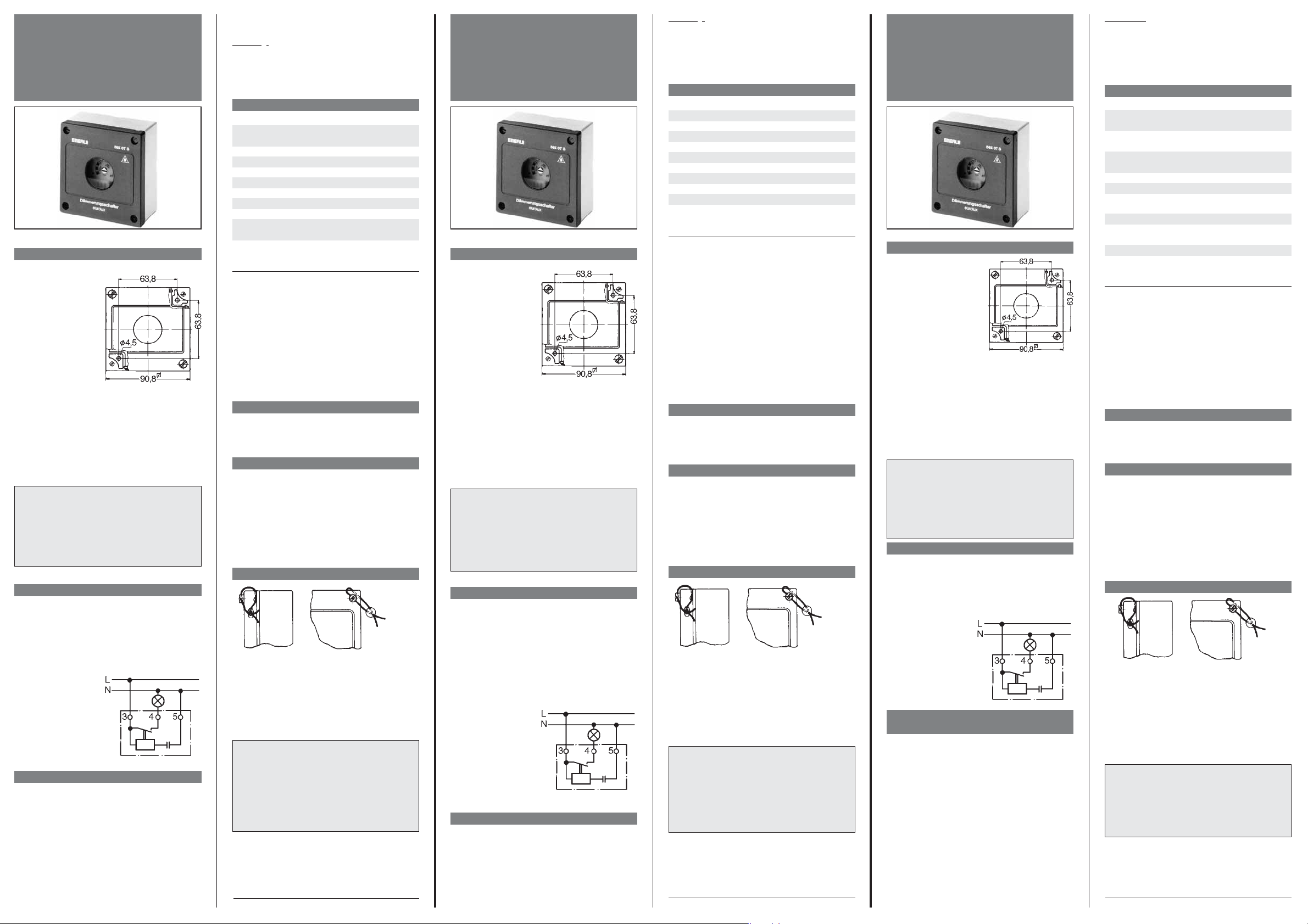
Die Befestigungslöcher (4,5 mm ∅) sind nach Abnahme des Gehäusedeckel (4 Schrauben) zugänglich. Achtung: Das Sichtfenster darf nicht durch das
einzuschaltende Licht beleuchtet werden!
2. Anschluss
Die Kabelzuführung (eine Leitung mit max. 3 x 2,5
mm
2
) darf nur von unten her in fester Verlegung
erfolgen. Nur dann ist eine wasserdichte Montage
gewährleistet. Das Durchschleifen einer Schutzleiterverbindung ist nicht möglich.
Dazu ist das Gehäuse
unterhalb der Klemmen 3, 4, 5 auszubrechen und der Gummiverschluss einzusetzen.
Der Anschluss erfolgt
gemäß dem Schaltbild
auf der Elektronikabdeckung.
3. Einstellen der Lichtempfindlichkeit
Der Ansprechwert des Dämmerungsschalters ist
ab Werk auf ca. 10 Lux eingestellt. Andere Ansprechwerte (zwischen 1-100 Lux) können bei abgenommenem Deckel mit einem Schraubendreher eingestellt werden. Auf der Skala der Elektronikabdeckung sind die verschiedenen Luxwerte
ersichtlich. Diese Werte gelten jedoch nur bei geschlossenem Gehäusedeckel!
Die Elektronikabdeckung darf nicht entfernt werden, da sonst keine einwandfreie Funktion gewährleistet ist.
ACHTUNG
Das Gerät darf nur durch einen Fachmann installiert bzw. eingesetzt werden. Dabei sind die bestehenden Sicherheitsvorschriften zu beachten.
Dieser unabhängig montierbare elektronische
Dämmerungsschalter dient zum Schalten von Beleuchtungseinrichtungen. Er arbeitet nach der
Wirkungsweise 1 C.
1. Installation Notes
The twilight switch
should be mounted
only on a smooth,
vertical surface, exposed to the north
(house walls) and
preferably avoiding
direct sunlight.
The device should be
mounted at a minimum height of 3 metres. Please make sure that it is not mounted under the shadow of trees or shrubs, as this would
cause it to switch off too late in the morning.
The fixing holes (diam. 4.5 mm) can be accessed
after removing the cover (4 screws). Warning: the
photocell opening should not be reached by the
light controlled by the twilight switch.
2. Wiring
Cable entry (one cable with max. 3 x 2.5 mm2) must
be from below with the wires firmly secured. Only
in this way can the water tightness of the housing
be ensured. Looping through of any earth connection will not be possible. To do this, the housing
must be pressed out below the terminals 3, 4 and 5
and the rubber grommets fixed. Make all connections by following the wiring diagram on the electronic equipment cover of the device.
3. Setting light sensitivity
The tripping value is factory set to approx. 10 Lux.
Other values from 1 to 100 Lux can be set by
means of a screwdriver after removing the front
cover. The photocell Lux range is clearly marked
on the electronic equipment cover. However, such
values only apply when the housing cover is
closed.
ATTENTION
The device should only be installed and mounted by a qualified technician, in compliance with
applicable safety regulations in force.
This electronic twilight switch is used for switching light equipment, it operates according
type 1C
Warning!
When fine tuning the twilight switch by setting the
desired switching point to the current lighting conditions, please bear in mind that for each adjustment
to become effective, you should wait for the switch
on/off delay time (approx. 30 sec.) to elapse.
4. Technical data
Type 565 07 S
Operating voltage 220 V +10%/-15% 50 Hz
Contact 1 n/o
Current rating *) 10 A/250 V~
Operating range**) approx. 1 – 100 Lux
On/off delay time approx. 30 sec.
Ambient temperature –30 to +55 °C
Protection rating IP 54
Rated impulse voltage 2.5 KV
Brinell test temperature 75°C
Voltage and current for
EMC emitted
interference testing 230 V; 0,1 A
*) Incandescent lamps max. 1600 W
Mercury lamp max. 1000 W
Sodium lamp max. 200 W
Fluorescent lamps
uncompensated max. 1000 W
compensated max. 600 W
dual-lamp circuit max. 2000 W
**) The regular operating range of a twilight
switch intended for outdoor use is approx. 730 Lux. Thanks to a wide setting range (approx.
1-100 Lux), this device can be set in an extremely precise way to meet the specific application requirements.
5. Suppression
The twilight switch is suppressed to VDE 0875 class
N, and is built in compliance with the European Directive 82/49/EEC.
6. Operation
In full light the relay contact is open. When the
light level falls below the set value the relay is excited after the delay time. When the light level exceeds the set value, the relay drops out after the
delay time. The delay is included to ensure that the
relay is not energised by short duration sources of
light, e.g. car headlamps, lightning flashes etc.
7. Sealing the housing
1. Remove the top right cover screw and replace it
with the seal screw supplied which has a transverse hole.
2. Pass the seal wire through the channel in the
cover and through the seal screw. Crimp the
lead seal in the usual way.
NOTE
The 565 07 is intended mainly for use in the private sector e.g. driveways, garages, porches etc.
For industrial and commercial applications such
as street lighting, filling stations, underpasses
etc. the twilight switch type 565 15 is considered
more suitable.
1. Instructions de montage
L'interrupteur crépusculaire doit être monté sur une surface plane verticale, située au
nord, non exposée au
rayonnement solaire.
Cet appareil ne doit pas
être installé à moins de 3
mètres du sol ni à l’ombre
d’arbres ou d’arbustes. Sinon l’interrupteur crépusculaire s’éteint trop tard le matin.
Les trous de fixation (∅ 4,5 mm) sont accessibles
en enlevant le couvercle (4 vis).
Attention: l’orifice du couvercle, permettant le
contrôle de la luminosité, ne doit pas être éclairé
par la lumière commandée par l’interrupteur crépusculaire.
2. Raccordement
Le raccordement du câble électrique (un cable de
max. 3 x 2,5 mm
2
) doit impérativement se faire par
le bas de l’appareil pour garantir l’étanchéité, le fil
de terre ne peut former de boucle.
Il faut évider le boîtier sous les bornes 3, 4, 5 et
mettre le joint caoutchouc en place.
Le raccordement électrique se fait conformément au schéma
marqué sur la plaque
de recouvrement de
l’électronique.
3. Réglage de la sensibilité
de luminosité
Le seuil d’enclenchement de l’interrupteur crépusculaire est réglé en usine à 10 Lux env. ce qui
correspond à la valeur la plus usitée. D’autres
seuils peuvent être réglés (de 1 à 100 Lux) au
moyen d’un tournevis, une fois le couvercle enlevé.
La plage de réglage est indiquée sur la plaque de
recouvrement de l’électronique. Les valeurs ne
sont néanmoins valables que lorsque le couvercle
est à nouveau mis en place. Cette plaque de recouvrement de l’électronique ne doit jamais être
enlevée pour pouvoir garantir un fonctionnement
correct.
Le boîtier doit être clos soigneusement, pour éviter l’introduction de l’humidité.
ATTENTION
L'appareil ne doit être installé et monté que par un
professionnel qualifié et conformément aux normes
de sécurité en vigueur.
Cet interrupteur crépusculaire électronique est destiné à l'utilisation d'équipements d'éclairage et fonctionne selon le type 1C.
IMPORTANT:
L’interrupteur crépusculaire de type 565 07 est prévu pour un usage domestique, tel que: éclairage de
rampe de garage, de vitrines, de cours etc.
Pour un usage industriel et publique, tel que éclairage routier, panneaux indicateurs, nous vous recommandons notre appareil de type 565 15.
Irrtum und Änderungen vorbehalten
Errors possible/subject to alterations
Sous réserve d’erreurs
U 468 931001 437-03
Montage- und
Bedienungsanleitung
Dämmerungsschalter
Typ 565 07 S
Attention!
Lors de la mise au point de l’interrupteur crépusculaire,
c’est-à-dire lorsqu’on fait correspondre le seuil de réglage avec les conditions de luminosité du moment, il faut
tenir compte que pour chaque réglage, on doit attendre
que la temporisation à l’enclenchement et au déclenchement (30 sec. environ) soit écoulée.
4. Caractéristiques techniques
Type 565 07 S
Tension nominale 220 V +10%/-15%
50 Hz
Type de contact 1 contact nor-
malement ouvert
Courant nominal *) 10 A/250 V,
50 Hz résistif
Plage de réglage**) env. 1 – 100 Lux
Temporis. Enclench./Déclench.env. 30 secondes
Température ambiante
admissible –30° à +55 °C
Classe de protection IP 54
Surtension transitoire
dimensionnée 2,5 KV
Température d’essai Brinell 75°C
Tension et courant de
contrôle de compatibilité
électromagnétique 230 V; 0,1 A
*) Lampes à incandescence max. 1600 W
Lampe à mercure max. 1000 W
Lampe à sodium max. 200 W
Lampes fluorescentes
non compensées max. 1000 W
compensées max. 600 W
circuit à deux lampes max. 2000 W
**) La plage de fonctionnement normale d’un interrup-
teur crépusculaire installé en plein air est comprise
entre 7 et 30 Lux environ. La plage de réglage comprise entre 1 et 100 Lux, permet un réglage très précis de
cet appareil dans ce domaine d’utilisation.
5. Anti-parasitage
L’interrupteur crépusculaire est anti-parasite selon
VDE 0875 classe N ; il est conforme à la directive
européenne 82/499/CEE.
6. Fonctionnement
Le contact relais est ouvert en cas de haute luminosité. Lorsque la luminosité descend au-dessous
du seuil réglé, le relais s’excite après la temporisation. Lorsque la luminosité dépasse à nouveau le
seuil, le relais revient à sa position de repos, toujours après la temporisation. Cette temporisation
sert à éviter l’enclenchement intempestif de l’appareil causé par des sources de luminosité de
courte durée (phares de voitures, éclairs, etc.)
7. Plombage du boîtier
1. Remplacer la vis en haut à droite du couvercle
par la vis de plombage fournie (avec perçage
transversal).
2. Faire passer le fil de plombage à travers le perçage de la vis de plombage et l’évidement présent dans le couvercle. Installer le plomb à sceller.
Page 2
1. Instrucciones de montaje
El interruptor crepuscular se debe instalar
solamente en superficies lisas, verticales y
orientadas al norte
(paredes de la casa),
evitando en lo posible
la luz solar directa.
El interruptor repuscular se debe montar
a una altura de por lo menos 3 m del suelo y nunca en la sombra de árboles o arbustos, para que
no desconecte demasiado tarde por las mañanas.
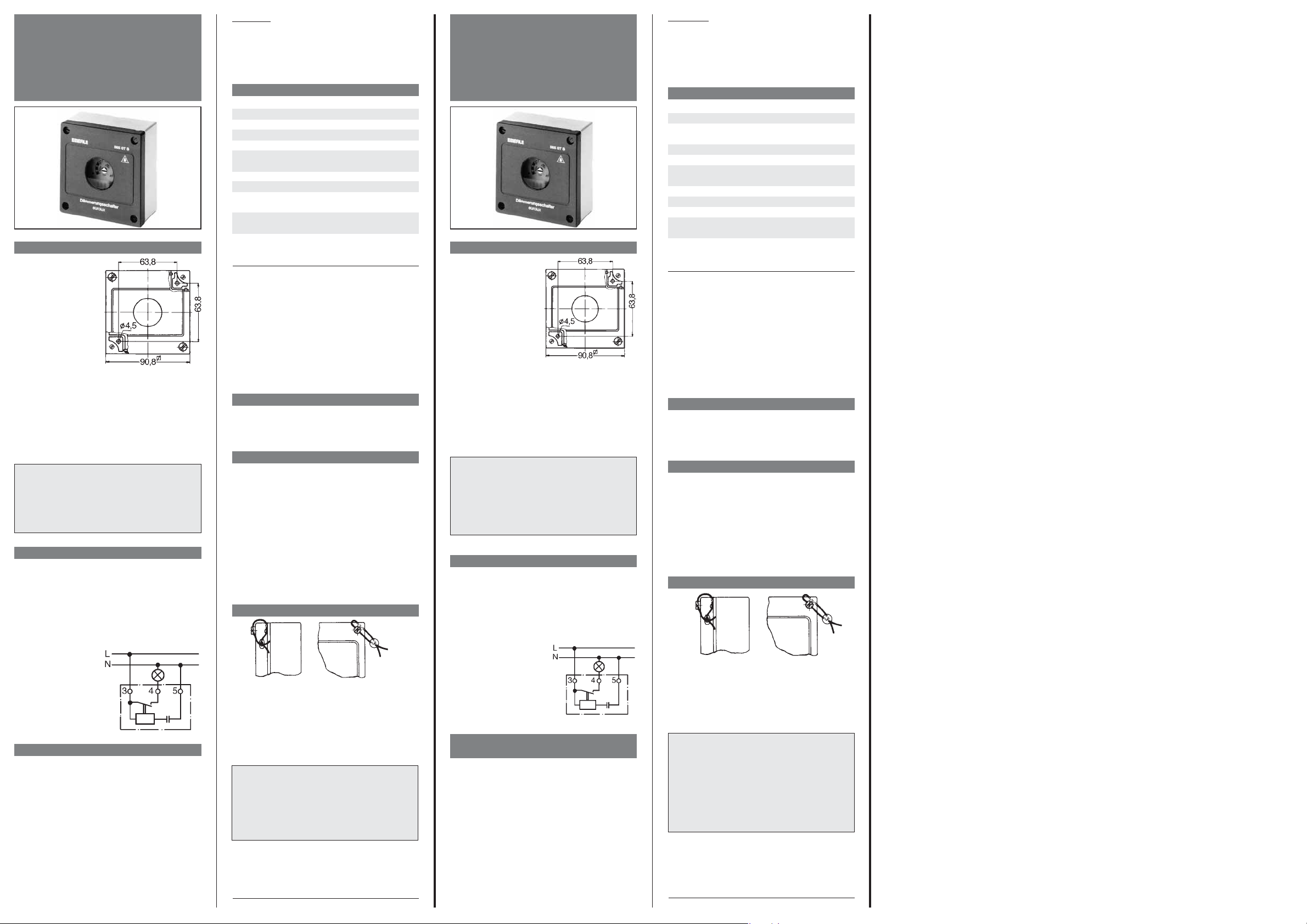
Es posible acceder a los orificios de montaje (4,5
mm de
∅) quitando la tapa del aparato (4 torni-
llos). Atención: la ventana transparente del aparato no debe ser iluminada por la luz que éste enciende.
2. Conexión
Para asegurar la estanqueidad al agua de la caja, la
entrada de cable (un cable con máx. 3 x 2,5 mm
2
)
se debe efectuar exclusivamente desde la parte inferior y debe ser de tipo fijo. No es posible conectar dos bornes entre sí con el neutro.
Es necesario, en cambio, romper los pretroquelados que se
encuentran bajo los
bornes 3, 4 y 5 y colocar la junta de goma.
La conexión se realiza
según el esquema presente en la tapa que
cubre la parte electrónica.
3. Ajuste de la sensibilidad a la luz
El interruptor crepuscular se programa en fábrica
con un nivel de iluminación al que se encenderá la
luz de aproximadamente 10 Lux. Es posible ajustar
otros valores (entre 1 y 100 Lux) con un destornillador, luego de haber quitado la tapa de la caja.
En la tapa que cubre la parte electrónica del aparato aparece la escala con los distintos valores de
Lux, que son válidos únicamente con la tapa de la
caja cerrada.
El correcto funcionamiento del interruptor queda
garantizado solamente con la tapa que cubre la
parte electrónica en su lugar. Se debe cerrar cuidadosamente la caja para evitar la penetración de
aqua.
ATENCIÓN:
Este aparato debe ser instalado por un profesional
cualificado, y en cumplimiento con las normas de seguridad pertinentes. Este interruptor crepuscular
electrónico se emplea para la conexión de luces y trabaja según el tipo 1C.
Posible errors/Sujeto a modificaciones
1. Istruzioni per il montaggio
L’interruttore crepuscolare deve essere installato esclusivamente
su superfici lisce, verticali, ed esposte a nord
(muri dell’abitazione),
evitando se possibile
l’esposizione alla luce
solare diretta.
L’apparecchio non deve essere installato ad una altezza inferiore ai 3 m, né all’ombra di alberi o arbusti,
altrimenti il crepuscolare si spegnerà troppo tardi al
mattino.
E’ possibile accedere ai fori di fissaggio (mm 4,5 Ø)
togliendo il coperchio del contenitore (4 viti).
Attenzione: la finestra dello strumento non deve
essere illuminata dalla luce accesa dallo stesso.
2. Connessione elettrica
L’entrata dei cavi (un conduttore max. 3 x
2,5 mm2) deve essere fissa e provenire dal basso,
per poter garantire un montaggio impermeabile
all’acqua. Non è possibile ponticellare il neutro.
Si devono invece utilizzare gli sfondabili presenti
nel contenitore, in corrispondenza dei morsetti 3,
4 e 5, applicando gli appositi tappi in gomma.
Il collegamento deve
essere eseguito come
indicato dallo schema
elettrico riportato sulla copertura a protezione della parte elettronica.
3. Impostazione della sensibilità
alla luce
La soglia di intervento del crepuscolare viene impostata in fabbrica su circa 10 Lux. È possibile impostare altre soglie di intervento (tra 1 e 100 Lux)
con un cacciavite, dopo aver tolto il coperchio. I
diversi valori di Lux sono chiaramente specificati
nella scala indicata sulla copertura a protezione
della parte elettronica. Tuttavia, tali valori sono
validi soltanto con il coperchio del contenitore
chiuso.
Per poter garantire un funzionamento ottimale, la
copertura a protezione della parte elettronica non
deve essere rimossa.
Il contenitore deve essere accuratamente chiuso
per evitare la penetrazione di acqua.
ATTENZIONE
Il dispositivo dovrebbe essere installato e montato
solo da tecnici qualificati, secondo le attuali norme di
sicurezza locali.Questo interruttore crepuscolare è
utilizzato per attivare dispositivi d'illuminazione, e
opera in accordo con il tipo 1C.
Attenzione:
Nell’effettuare la regolazione fine del crepuscolare,
facendo corrispondere il punto di intervento desiderato alle attuali condizioni di luminosità, bisogna
tenere conto che per ogni impostazione sarà necessario attendere la scadenza del ritardo di intervento
all’accensione o allo spegnimento (30 secondi circa).
4. Dati tecnici
Codice 565 07 S
Tensione di alimentazione 220V +10%/-15% 50 HZ
Contatto 1 contatto
normalmente aperto
Portata del contatto*) 10 A/250V~
Campo di regolazione**) da 1 a 100 Lux
Ritardo di intervento 30 sec. circa
Accensione/Spegnimento
Temperatura ambiente –30...+55°C
Grado di protezione IP 54
Tensione nominale impulsiva 2,5 KV
Temperatura per la verifica
di durezza alla sfera 75°C
Tensione e corrente per le
verifiche di compatibilità
elettromagnetica 230 V; 0,1 A
*) Lampadine ad incandescenza max. 1600 W
Lampade a vapori di mercurio max. 1000 W
Lampade a vapori di sodio max. 200 W
Lampade fluorescenti
non compensate max. 1000 W
compensate max. 600 W
circuito bilampada max. 2000 W
**) Il campo di lavoro normale di un interruttore crepu-
scolare utilizzato all’aperto è compreso tra 7-30 Lux
circa. L’ampio campo di regolazione compreso tra 1100 Lux circa, permette di impostare l’apparecchio in
maniera molto precisa per questo tipo di applicazione.
5. Protezione contro radiodisturbi 3
L’interruttore crepuscolare è protetto contro i radiodisturbi secondo la norma VDE 0875, con grado di protezione N, ed è rispondente alla Direttiva
CE 82/499CEE.
6. Funzionamento
In piena luce, il contatto del relè è aperto. Quando
la luce scende al disotto del valore impostato, il
relè viene eccitato dopo un tempo di ritardo.
Quando la luce supera nuovamente il valore impostato, il relè viene diseccitato dopo un tempo di
ritardo.
Il ritardo di intervento evita inserimenti
inopportuni dovuti a fonti luminose di disturbo di
breve durata (ad es. fari delle macchine, lampi).
7. Piombatura del contenitore
1. Sostituire la vite superiore destra del coperchio
con l’apposita vite da piombatura fornita in dotazione (con foro trasversale).
2. Far passare il filo attraverso la scanalatura pre-
sente nel coperchio e nella vite da piombatura
ed applicare il piombino.
Salvo errori e cambiamenti
Avvertenza importante:
Questo strumento è adatto per applicazioni
nel settore privato, ad esempio per l’illuminazione di viali di accesso, garage, vetrine, ecc.
Per applicazioni industriali e negli impianti
pubblici (illuminazione stradale, illuminazione
per la segnalazione di pericoli, ecc.) è disponibile il nostro interruttore crepuscolare modello DA 565 15.
Advertencia importande:
Este aparato es apto para su uso en el ámbito privato,
por ejemplo para la iluminación de caminos de entrada, garajes, escaparates, etc.
Para aplicaciones industriales y en instalaciones públicas como la iluminación vial, la iluminación para la
señalización de peligros, etc. está disponible nuestro
interruptor crepuscular modelo DA 565 15.
U 468 931001 437-03
Instrucciones de
montaje y empleo
Interruptor crépuscular
Tipo 565 07 S
U 468 931001 437-03
Istruzioni per il montaggio
e l’uso
Interruttore crepuscolare
Modello 565 07 S
¡Cuidado!
Al realizar el ajuste fino del interruptor crepuscular,
haciendo coincidir el punto de interrupción deseado
con el nivel de iluminación ambiente actual, se debe
tener en cuenta que cada vez que se ajuste un valor
habrá que dejar transcurrir la temporización a la conexión, que es de aproximadamente 30 segundos.
4. Datos técnicos
Tipo 565 07 S
Tensión de alimentación 220 V +10%/-15% 50 Hz
Contacto 1 contacto N.A.
Intensidad nominal *) 10 A/250 Vca
Rango de ajuste**) aprox. 1 a 100 Lux
Retardo a la
conexión/desconexión aprox. 30 seg.
Temperatura ambiente –30° a +55°C
Grado de protección IP 54
Tensión de corriente
asignada 2,5 KV
Temperatura para ensayo
de dureza Brinell 75°C
Tensión y corriente para
control de compatibilidad
electromagnética 230 V; 0,1 A
*) Lámparas deincandescencia máx. 1600 W
Lámpara de mercurio máx. 1000 W
Lámpara de sodio máx. 200 W
Lámparas fluorescentes
sin compensar máx. 1000 W
compensadas máx. 600 W
circuito con dos lámparas máx. 2000 W
**) El rango de funcionamiento normal de un interrup-
tor crepuscular para uso al aire libre está comprendido entre 7 y 30 Lux aproximadamente. El amplio rango de ajuste de aprox. 1 a 100 Lux permite regular el
aparato de manera extremadamente exacta para este
campo de aplicación.
5. Supresión de interferencias
El interruptor crepuscular tiene grado de antiparasitaje N según la norma VDE 0875 y cumple con la
directiva 82/499/CEE.
6. Funcionamiento
Mientras que el nivel de iluminación es alto, el contacto relé permanece abierto. Cuando disminuye
por debajo del valor ajustado, el relé se excita tras
una temporización de aproximadamente 30 segundos. Cuando el nivel de iluminación vuelve a
subir por encima del valor ajustado, el relé vuelve a
la posición de reposo, tampién tras una temporización de aproximadamente 30 segundos.
Dicha temporización permite evitar una conmutación intempestiva del aparato debida a fuentes luminosas de perturbación de corta duración (como
por ej. faros de los autos, relámpagos, etc.).
7. Precintado de la caja
1. Sustituya el tornillo superior derecho de la tapa
por el tornillo precintable suministrado (con
agujero transversal).
2. Pase el alambre de precinto a través de la
canaleta de la tapa y el tornillo perforado y coloque el precinto.
 Loading...