

Page 1
*Note:
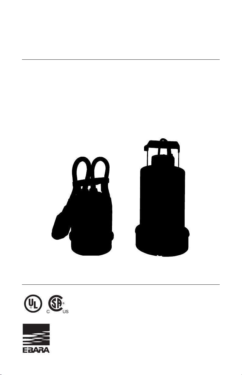
UL and CSA listed; Model Optima UL certified only.
Page 2

Thank you for purchasing this EBARA Stainless Steel Sump
Pump. We hope you are pleased with your purchase and that
our pumps will provide you with long service life and exceptional performance.
To ensure satisfactory service life, there are several considerations regarding proper installation, operation and power
source. Please review the recommendations outlined within
the installation and operation manual.
Please contact your supplier (supplying dealer or contractor)
if service is necessary or if you have any questions or need
further assistance.
Please retain the following information for your records and to
help expedite service:
Purchase Date: ____________________________
Purchased From: ____________________________
____________________________
Serial No: ____________________________
(Located on the pump nameplate)
Note: For assistance locating the serial number and name plate, please
refer to page 17 of your owner’s manual.
EBARA Fluid Handling
www.pumpsebara.com
1651 Cedar Line Drive • Rock Hill, SC 29730 • (803) 327-5005 • (803) 327-5097
(fax)
Page 3

EBARA Fluid Handling
www.pumpsebara.com
5
(t) 803 327-5005 • (f) 803 327-5097
rev. 12/07
EBARA Submersible Sump/Drainage Pumps EPD / Optima
Important Safeguards
To reduce risk of injury,
always
follow these instructions and safety precautions
when using this pump and to maintain warranty.
Read All Instructions Prior to Installation
(SAVE THESE INSTRUCTIONS)
Installation/Operation:
• Never lift or carry pump by the electrical cord. Use a chain or rope affixed
on handle to install/remove pump. To reduce potential damage to the pump
from inadvertent lifting by the electrical cord, please refer to “Proper Lifting”
located on the following page.
• This pump must be operated fully submerged. Pump must be shutdown if
sump, pit or pond level drops below the motor housing.
• Pump is designed to pump clean water (maximum temperature of 122
••
F)
with suspended solids up to 3/8 of an inch. Larger solids will clog the
suction strainer plate leading to dry running and subsequent failure (
Note:
Pumping sand, gravel, and other hard debris will shorten the life of the
pump)
. Elevate the pump with bricks or other support above the sump, pit or
pond bottom if debris is present. Consult dealer for other fluids.
• Clean filter basin when cleaning inlet filter media when pump is shutdown.
• If used with a float switch, the float must have a full range of motion to
operate properly without obstruction. Consult dealer for minimum dimensions
required for proper float operation.
• Pump should be mounted upright only (vertical). Never lay the pump on its side.
Electrical Requirements:
• Pump must be operated with a GFI breaker of at least 20 amps.
• High OR Low Voltage can damage the pump. Power from your utility or generator
set cannot be more or less than ±5% of the rated voltage on the pump.
• Maximum distance from power source and pump must not exceed 100 feet
using 16/3 electrical cables. This distance is from the breaker box and
includes the pump cord. If the run is longer, consult a qualified electrician or
your dealer.
• Lightning strikes can destroy the capacitor in your pump. Ensure proper
protection is provided.
• Consult operator manual for other operation and application information.
Page 4

EBARA Fluid Handling
www.pumpsebara.com
6
(t) 803 327-5005 • (f) 803 327-5097
rev. 12/07
EBARA Submersible Sump/Drainage Pumps EPD / Optima
Important Safeguards
Proper Lifting:
A separate chain or rope should be attached to the handle for normal lifting.
Please note that this will help prevent damage due to inadvertent lifting of
the pump by the power cord.
Rope attached to automatic pump
for lifting and installation.
Rope attached to manual pump for
lifting and installation.
Page 5

EBARA Fluid Handling
www.pumpsebara.com
7
(t) 803 327-5005 • (f) 803 327-5097
rev. 12/07
EBARA Submersible Sump/Drainage Pumps EPD / Optima
Section Page
General Application Information . . . . . . . . . . . . . . . . . . . . . . . . . . . . . . . . . . . 7
Safety Information and Introduction & Specifications . . . . . . . . . . . . . . . . . . . 9
Materials/Tools & Installation Instructions . . . . . . . . . . . . . . . . . . . . . . . . . . . 10
Pump Inspection & Installation Instructions . . . . . . . . . . . . . . . . . . . . . . . . . . 11
Fixed Application Diagram & Performance Table . . . . . . . . . . . . . . . . . . . . . 13
Manual Operation Type Motor Wiring Diagram . . . . . . . . . . . . . . . . . . . . . . . 15
Automatic Operation Type Motor Wiring Diagram . . . . . . . . . . . . . . . . . . . . . 15
Three Phase Motor Wiring Diagram . . . . . . . . . . . . . . . . . . . . . . . . . . . . . . . 16
Specifications . . . . . . . . . . . . . . . . . . . . . . . . . . . . . . . . . . . . . . . . . . . . . . . . . 18
Nameplate Data & Model No./Item No. Explanation . . . . . . . . . . . . . . . . . . . 20
Troubleshooting Checklist & Maintenance Info . . . . . . . . . . . . . . . . . . . . . . . 21
Date Code Information . . . . . . . . . . . . . . . . . . . . . . . . . . . . . . . . . . . . . . . . . 22
Sectional View & Parts Reference . . . . . . . . . . . . . . . . . . . . . . . . . . . . . . . . . 23
Disassembly & Assembly Info . . . . . . . . . . . . . . . . . . . . . . . . . . . . . . . . . . . . 32
Warranty Information . . . . . . . . . . . . . . . . . . . . . . . . . . . . . . . . . . . . . . . . . . . 33
The Sump and Installation
If your basement does not currently have a sump installed, it would be necessary
to
check local plumbing codes as to the acceptable type of sump that may be used.
Materials commonly specified are: clay tile, fiberglass, steel, concrete and
polyethylene.
It may be necessary to cut a hole in the basement floor and excavate
for the sump.
Plumbing and electrical contractors could advise you on proper installations of drain
tiles, sump, pump and electrical service. EBARA recommends that a solid sump base
be provided. The sump is fed by drain tile placed around the outside and/or inside basement walls at the footings. In applications where a gravel base must be used to relieve
hydraulic pressure under the basement floor, be sure to provide a permanent and solid
base for the pump (bricks or a steel plate). A sump cover capable of supporting 200
pounds should be employed to contain odors and for obvious safety reasons.
Electrical Installation
Electrical service for any sump pump installation must be grounded and separately fused
or breakered directly from the entrance box with a single grounding type receptacle at
the pump. The receptacle should not be less than four feet above the basement floor for
Contents
General Application Information
Page 6

EBARA Fluid Handling
www.pumpsebara.com
8
(t) 803 327-5005 • (f) 803 327-5097
rev. 12/07
EBARA Submersible Sump/Drainage Pumps EPD / Optima
safety reasons. You should never touch a sump pump or discharge piping while the
pump is connected to electrical power and water is present. The pump should be
disconnected from the electrical source before handling in all cases.
Discharge Piping Installation
To assure the maximum performance from your sump pump, the discharge pipe size
and piping fittings should not be smaller than the discharge port of the pump. Smaller
pipe will add to friction losses and reduce the capacity of the pump. Normally accepted
materials are galvanized pipe, rigid plastic pipe or
acceptable flexible pipe or hose. A piece
of flexible hose between the pump discharge
and the discharge piping will provide for ease
in alignment, reduce vibration and noise, and will act as a union when it is necessary to
remove the pump. Where the discharge pipe is long, a check valve is often employed to
prevent the water from flowing back into the sump when the pump turns off. If the discharge
is directed into a sanitary sewer, a suitable anti-siphon device or a free flow check valve
should be inserted in the line to prevent backflow into the pit. Sump pumps are not
designed to handle raw sewage. Do not attempt to adapt one for this type of application.
A sewage ejector pump especially designed to handle solids must be used.
Pump Installation
When the sump, electrical and discharge plumbing installation is complete and ready for
the pump, clean all solid debris from the pit. Complete the plumbing connection to the
pump and then plug the pump into the electrical outlet. A few extra minutes to test the
sump pump installation are now in order. Fill the sump with water, note the turn on and
turn off level of the pump, and the pumping cycle. This will allow you to calculate the
approximate discharge flow of the pump system. If everything is operating properly,
install the sump cover.
Pump Selection
The pump should be of sufficient capacity and head to satisfy anticipated use requirements. Capacity is determined by a fixture unit value if effluent is drained to sump basin.
Your local Wholesaler can assist you in fixture unit values.
Basement perimeter water intrusion varies by area and region. Typically a 1/3 HP or 1/2
HP DRAINAGE PUMP WILL EVACUATE MOST HOME SUMP PITS.
Commercial and industrial drainage applications require that calculations of pumping
volume and pumping head be performed to determine the proper size pump is applied.
NOTE:
Pumping volume may vary seasonally due to rainfall and area run-off.
General Application Information
(cont.)
Page 7
EBARA Fluid Handling
www.pumpsebara.com
9
(t) 803 327-5005 • (f) 803 327-5097
rev. 12/07
EBARA Submersible Sump/Drainage Pumps EPD / Optima
Required Minimum
Pump Capacity Basin Diameter
up to 35 GPM 18"
over 35 GPM 24"
over 60 GPM 30"
over 100 GPM 36"
over 150 GPM 48"
General Application Information
(cont.)
Safety Information and Introduction
Before handling this pump, always disconnect
the power first.
This pump should only be serviced by a qualified person or a factory
trained person.
Basin and Cover
The basin should not be less than 18 inches in diameter and 24 inches deep.
Larger diameters are advisable in instances of increased pump capacity requirements:
The basin should be located such that all water flows into the basin due to gravity.
Outdoor installations should be at a sufficient depth to ensure protection from freezing.
Note:
Optima-3SS1 and EPD-3SS1 slimline automatic can operate in a 12'' diameter
basin or 8'' x 8'' square basin.
Maintenance Tips
• Every three or four months:
1) Clean the pump screen or inlet opening. If your sump collects the discharge
from an automatic washing machine, cleaning will be required more often. (Before
removing the pump be sure to disconnect the unit from electrical power; and
reconnect after completion of cleaning);
2) Pour enough water into the sump to cycle the pump and assure its proper
functioning.
• Annually:
Remove and clean the pump. Clean the sump pit also.
WARNING
!
CAUTION
This instruction manual includes necessary items for installation, operation
and maintenance.
Read this manual carefully to ensure correct installation,
operation and maintenance.
Be sure to keep this instruction manual on hand for future reference.
!
Page 8
EBARA Fluid Handling
www.pumpsebara.com
10
(t) 803 327-5005 • (f) 803 327-5097
rev. 12/07
EBARA Submersible Sump/Drainage Pumps EPD / Optima
Check the nameplate for your pump’s head (HEAD), discharge volume (CAPACITY), speed
(SPEED), motor voltage and current. Other specifications are noted in the chart below:
ITEM NO. MODEL DISCHARGE MOTOR MOTOR WEIGHT
SLIMLINE DIA. OUTPUT PHASE VOLTAGE
AUTOMATIC OPERATION INCH (HP)
Optima-3SS1 32Z707SU6.35S/A 1
1
/
4
1/3 1 115 11
EPD-3SS1 32P707SU6.35S/A 1
1
/
4
1/3 1 115 11
20 FT POWER CORDS – AVAILABLE ON MOST MODELS
ITEM NO. MODEL DISCHARGE MOTOR MOTOR WEIGHT
DIA. OUTPUT PHASE VOLTAGE
MANUAL OPERATION INCH (HP)
Optima-3MS1 32Z707U6.3S/A 1
1
/
4
1/3 1 115 11
EPD-3MS1 32P707U6.3S/A 1
1
/
4
1/3 1 115 11
EPD-5MS1 40P707U6.6S 1
1
/
2
1/2 1 115 27
EPD-5MT2 40P707U6.62 1
1
/
2
1/2 3 230 27
EPD-5MT4 40P707U6.64 1
1
/
2
1/2 3 460 27
EPD-7MS1 40P707U6.9S 1
1
/
2
3/4 1 115 28
EPD-7MT2 40P707U6.92 1
1
/
2
3/4 3 230 28
EPD-7MT4 40P707U6.94 1
1
/
2
3/4 3 460 28
EPD-10MT2 40P707U61.12 1
1
/
2
1 3 230 31
EPD-10MT4 40P707U61.14 1
1
/
2
1 3 460 31
EPD-15MT2 40P707U61.32 1
1
/
2
11/
2
3 230 31
EPD-15MT4 40P707U61.34 11/
2
11/
2
3 460 31
20 FT POWER CORDS – AVAILABLE ON MOST MODELS
ITEM NO. MODEL DISCHARGE MOTOR MOTOR WEIGHT
DIA. OUTPUT PHASE VOLTAGE
AUTOMATIC OPERATION INCH (HP)
Optima-3AS1 32Z707AU6.3S/A 1
1
/
4
1/3 1 115 11
EPD-3AS1 32P707AU6.3S/A 11/
4
1/3 1 115 11
EPD-5AS1 40P707AU6.6S 11/
2
1/2 1 115 27
EPD-7AS1 40P707AU6.9S 11/
2
3/4 1 115 27
20 FT POWER CORDS – AVAILABLE ON MOST MODELS
Be careful not to exceed the given specifications in the use of your products.
• Screw driver
• Pipe wrench
• Adjustable wrench (medium-large)
• Hacksaw with 24-tooth blade for cutting plastic pipe
• Knife or round file for smoothing inside of all plastic pipe connections
Specifications
Tools Needed
CAUTION
!
Page 9

EBARA Fluid Handling
www.pumpsebara.com
11
(t) 803 327-5005 • (f) 803 327-5097
rev. 12/07
EBARA Submersible Sump/Drainage Pumps EPD / Optima
• PVC or ABS pipe cement
(read manufacturer’s instructions carefully)
• PVC or ABS pipe;
– 11/4" for Optima-3 & EPD-3
– 11/2" for EPD-5,7,10 & 15
• PVC adapter
– 11/4" for Optima-3 & EPD-3
– 11/2" for EPD-5, 7, 10 & 15
• In line check valve
• Sump basin 18” or larger diameter plastic, fiberglass or concrete.
(See page 2 for minimum diameter basin size by pump capacity.)
• Optional: gate valve
(see installation drawing on page 6)
Step 1 Inspection: Your pump has been carefully packaged to prevent damage during
shipping. However, occasional damage does occur due to rough handling. Carefully
inspect the pump for damage that could cause it to fail.
Step 2: Attach desired length of PVC or ABS discharge pipe to pump outlet, using PVC
adapter (11/4" pipe and adapter for Optima-3 & EPD-3 11/2" for EPD-5, 7, 10 & 15). Make
sure open end of pipe will be above top of basin.
Step 3: Clear sump basin of any water, debris or sediment.
Step 4: Lower pump into basin.
Step 5: Attach in line check valve to discharge pipe 12" to 18" above pump discharge
with arrow pointing away from the pump (with the flow). Connect other end of check
valve securely to drain pipe and tighten clamps.
Note:
Do not put check valve directly into pump discharge opening.
Step 6: Drill a 1/8" relief hole in the discharge pipe 5" above pipe connection to pump.
Step 7: Plug in pump and fill sump basin with water to test unit. Pump should turn on at
13" to 14" water level. Allow pump to go through several ON-OFF cycles to assure satisfactory operation.
Note:
If pump does not operate properly, see the troubleshooting checklist on page 12.
Septic Tank Installation
The PRO•DRAINER pumps can be used to pump septic tank effluent, but must be
installed as follows:
• Install pump in separate compartment at the discharge side of the septic tank. Never
install pump in main tank where sludge collects.
• Use with a junction box.
WARNING: Sump basin must be vented in accordance with local plumbing codes.
These pumps are not designed for and CANNOT be installed in locations classified as
hazardous in accordance with the National Electric Code, ANSI/NEPA 70-1984.
Materials Needed
Installation Instructions
Page 10
EBARA Fluid Handling
www.pumpsebara.com
12
(t) 803 327-5005 • (f) 803 327-5097
rev. 12/07
EBARA Submersible Sump/Drainage Pumps EPD / Optima
• Pumps are 115 V, 60 Hz and are grounded to prevent electrical shock.
WARNING: Risk of electric shock—this pump is supplied with a grounding conductor
and grounding-type attachment plug. To reduce the risk of electric shock, be certain that
it is connected only to a properly grounded, grounding-type receptacle.
• Use a separate 20 amp circuit breaker or 20 amp fuse block with the pump.
• Do not use an extension cord with the pump.
• Do not cut off the ground pin or use an adapter fitting.
• Do not work on the pump or switch until any or all power cords are unplugged.
1. Before installing or servicing your pump, BE CERTAIN pump power source is disconnected.
2. Installation and electrical wiring must adhere to state and local codes and must be
complete before priming pump. Check appropriate community agencies, or contact
local electrical and pump professionals.
3. CALL AN ELECTRICIAN WHEN IN DOUBT. Pump should be connected to a separate
20 amp circuit breaker or 20 amp fuse block. Plugging into existing outlets may cause low
voltage at motor, causing blown fuses, tripping of motor overload, or burned out motor.
4. Do not connect pump to a power supply until permanently grounded. For maximum
safety, ground pump to a circuit equipped with a fault interrupter device.
5. Voltage of power supply must match the voltage of the pump.
6. Before installing pump, clear sump basin of any water, debris, or sediment.
WARNING: Sump basin must be vented in accordance with local plumbing
codes. EBARA PRO•DRAINERS are not designed for and CANNOT be installed
in locations classified as hazardous in the National Electric Code, ANSI/NFPA 70.
7. The sump basin should be between 18" and 24" in diameter and made of plastic,
fiberglass, or concrete.
8. The following may cause severe damage to pump and will void warranty:
• Using an extension cord.
• Cutting off the ground pin or using an adapted fitting.
• Working on pump or switch while plugged in.
• Removing motor housing, unscrewing impeller, or otherwise removing impeller seal.
PIPING
Plastic PVC pipe is shown in the illustrations, but galvanized steel or copper pipe may
be used if desired. All piping must be clean and free of all foreign matter to prevent
clogging. Use thread compound on all threaded joints unless specified otherwise.
IMPORTANT INSTRUCTIONS BEFORE INSTALLATION
Failure to follow these instructions may cause serious bodily injury and/or property damage.
Electrical information – Single Phase
(Refer to page 16 for Three
phase information)
Page 11

EBARA Fluid Handling
www.pumpsebara.com
13
(t) 803 327-5005 • (f) 803 327-5097
rev. 10/11
EBARA Submersible Sump/Drainage Pumps EPD / Optima
Refer to the installation illustration on the following page for the following instructions. Be
certain sump basin is clean and all power to pump is shut off. If pump fails to operate properly
after installation, refer to the troubleshooting checklist on page 12 or contact EBARA.
General Materials Needed
• One can PVC cement (read instructions carefully)
• One can thread compound (read instructions carefully)
• One male PVC adapter: 11/4" for 1/3HP; 11/2" for 1/2, 3/4, 1 & 11/2horsepower models.
• Enough rigid PVC pipe and couplings to reach from bottom of sump basin to discharge:
11/4" for 1/3HP; 11/2" for 1/2, 3/4, 1 & 11/2horsepower models.
• One Check Valve.
Tools Needed for all pump installations:
Pipe wrench, slot screwdriver, 24-tooth hacksaw, knife or round file.
Step 1 – Thread male PVC adaptor into pump discharge opening.
Step 2 – Cement a 15" piece of PVC pipe to adaptor. Use appropriate diameter piping.
Drill a 1/8" relief hole in the pipe 5" above pump connection. This hole prevents pump
from air-locking.
Step 3 – Clamp Check Valve to top of 15" PVC pipe with water flow arrow pointing
away from pump.
Step 4 – Lower pump into basin. Clamp needed PVC discharge pipe and fittings to
open end of Check Valve.
Step 5 – Plug in pump and fill sump basin with water. Pump should turn on at 13" to
14" water level. Perform several ON-OFF cycles to assure satisfactory operation.
TOTAL HEAD
ITEM NO
Optima-3
1/3 HP
EPD-3
1/3 HP
EPD-5
1/2 HP
EPD-7
3/4 HP
EPD-10
1 HP
EPD-15
1
1
/2HP
10
33
38
66
5
40
45
15
25
31
67
20
14
20
49
63
74
85
30
29
45
56
68
35
17
35
46
58
40
25
36
48
45
14
26
38
50
15
265515
25
7
40
54
65
77
GPMGPM GPM GPM GPM GPM
TOTAL HEAD
Submersible Pump Installation
Performance Table (Capacity in Gallons per Minute)
Page 12

EBARA Fluid Handling
www.pumpsebara.com
14
(t) 803 327-5005 • (f) 803 327-5097
rev. 12/07
EBARA Submersible Sump/Drainage Pumps EPD / Optima
101/2" Min.
14" Min.
Bottom of
inlet pipe
Sump pump
Drill 1/8" relief hole 5" above pump
discharge
Discharge piping can be PVC or
ABS plastic with proper adapters, or
can be galv. steel
shut-off
gate valve
(optional)
Turn on level
Grounded type
115 volt receptacle
or approved junction
box min. height
above floor – 4 ft.
Turn-off level
Lifting handle
Mechanical float switch
*All equipment other than pump to be
supplied by others. Pump only supplied
by EBARA.
1
1
/2" check valve
with rubber sleeve
connectors for
1
1
/4" and 11/2" pipe
Sump basin 18" to 24" dia.
plastic, fiberglass or concrete
PRO Drainer Submersible (Typical) Installation Diagram
Note:
Optima-3SS1 and EPD-3SS1 slimline automatic can operate in a 12'' diameter
basin or 8'' x 8'' square basin.
Page 13

EBARA Fluid Handling
www.pumpsebara.com
15
(t) 803 327-5005 • (f) 803 327-5097
rev. 12/07
EBARA Submersible Sump/Drainage Pumps EPD / Optima
Manual Operation Type Output (Three Phase)
• Output 1/2 to 11/2 HP
Automatic Operation Type Output (Single Phase)
• Output 1/3 to 3/4 HP
Manual Operation Type Output (Single Phase)
• Output
1
/3 to 3/4 HP
Motor Wiring Diagram
Page 14

EBARA Fluid Handling
www.pumpsebara.com
16
(t) 803 327-5005 • (f) 803 327-5097
rev. 12/07
EBARA Submersible Sump/Drainage Pumps EPD / Optima
Electrical Wiring – Three Phase
!
WARNING
Check that the power is locked off and disconnected before working on
pump. All electric work should be performed by a qualified electrician and all
national and local electrical codes must be observed.
NOTE:
Use with approved motor control that matches motor input in full load amperes with overload
element(s) selected or adjusted in accordance with control instructions.
Utiliser un démarreur approuvéconvenant au courant ápleine charge du moteur et dont les
élé
ments thermiques sont réglés ou choisis conformément aux instructions qui l’accompagnent.
(1) Wiring
a) Wire as indicated for the appropriate start system as shown in Fig. 4
b) Loose connections will stop the pump. Make sure all electrical connections are secure.
MOTOR WIRING DIAGRAM
• Model P707U
• Output
1
/2 to 11/2 HP
(2) Cable
a) Never let the end of the cable contact water.
b) If the cable is extended, do not immerse the splice in water.
c) Fasten the cable to the discharge piping with tape or vinyl strips.
d) Install the cable so that it will not overheat. Overheating is caused by coiling the
cable and exposing it to direct sunlight.
(3) Grounding
As shown in Fig. 5 ground the green/yellow wire (label E). Under no circumstances
should the green/yellow wire be connected to the power supply.
(4) Use short circuit breakers to prevent danger of electrical shock.
OPERATION
1. Before starting the pump:
(1) Check water level.
If the pump is operated continuously for an extended period of time in a dry condition
or at the lowest water level, the motor protector will be activated.Constant repetition of this
action will shorten pump service life. Do not start the pump again in such a situation until
after the motor has completely cooled.
(RED)
(BLACK)
(WHITE)
(GREEN/YELLOW)
Fig. 4
U phase: black
V phase: red
W phase: white
E phase: green/yellow
ground
plate
* Three phase only
Fig. 5
Page 15

EBARA Fluid Handling
www.pumpsebara.com
17
(t) 803 327-5005 • (f) 803 327-5097
rev. 12/07
EBARA Submersible Sump/Drainage Pumps EPD / Optima
SPECIAL NOTICE
for Cord Connected Pumps
EBARA EPD / Optima PRO Drainer pumps are NOT
designed for and CANNOT be installed in any location
classified as
hazardous
by the National Electric Code
ANSI/NFPA 70.
• Connection devices shall provide for a watertight connection to the power
supply and provide adequate strain relief for the cord.
• Installation of the box shall be a Listed watertight connection box used with
a Listed, liquid-tight fitting suitable for the cord.
• Connection boxes should be sized in accordance with National Electric
Code specifications and installed as intended for the application.
• All connection devices are to be provided by the installer.
• Only qualified personnel shall service and install the pump.
Page 16

EBARA Fluid Handling
www.pumpsebara.com
18
(t) 803 327-5005 • (f) 803 327-5097
rev. 12/07
EBARA Submersible Sump/Drainage Pumps EPD / Optima
Model Optima-3AS1
EPD-3AS1
Optima-3SS1
EPD-3SS1
EPD-5AS1 and EPD-7AS1
Automatic Operation Pumps Performance: ISO 2548
Standard Optional
Discharge Size
1
/3 HP – 11/4 inch
1
/2 HP and 3/4 HP – 11/2 inch
Range of HP
1
/3, 1/2, and 3/4 HP
Range of Performance Capacity 2.7 to 72 GPM
Head 9.3 to 57 feet
Limitation
Maximum Water Temperature 122°F/50°C
Solids
3
/8'' Spherical (2% by concentration)
Speed 3600 RPM
Materials
Casing 304L Stainless Steel
Impeller 304L Stainless Steel*
Shaft 303 Stainless Steel
Motor Frame 304L Stainless Steel
Fasteners 304L Stainless Steel
Shaft Seal (Double)**
Material – Upper Side NBR Fitted Carbon/Ceramic
1
/2, 3/4, 1, and 11/2 HP
Material – Lower Side NBR Fitted SiC/SiC
1
/2, 3/4, 1, and 11/2 HP
Impeller Type Semi-Open
Bearing Sealed Ball Bearing
Motor Air-filled, Insulation Class F, 2 Pole,
Rated Continuous Duty–
Permanent Split Capacitor
Single Phase 115 Volt
Motor Protection Built-in Motor Protection with
Auto Reset
Power Cord UL/CSA SJTow-A with ECS No. 250
capplug with grounding pin –
20 Ft. Length
Rated 15 Amp 125V – NEMA 5-15P
Automatic Float Switch Mechanical Float
* ITEM NO. Optima-3AS1 – Impeller material is Thermo Plastic-Noryl GFN2
** Optima-3 & EPD-3 –
1
/3 HP Shaft Seal is single mechanical seal (lower side) and 1 lip seal (upper side)
– Mechanical Seal material: Carbon/Ceramic/FPM
Specifications
Page 17

EBARA Fluid Handling
www.pumpsebara.com
19
(t) 803 327-5005 • (f) 803 327-5097
rev. 12/07
EBARA Submersible Sump/Drainage Pumps EPD / Optima
Model Optima-3MS1
EPD-3MS1
EPD-5 to 15
Manual Operation Pumps Performance: ISO 2548
Standard Optional
Discharge Size
1
/3 HP – 11/4 inch
1
/2 HP through 11/2 HP – 11/2 inch
Range of HP
1
/3, 1/2, 3/4, 1, and 11/2 HP
Range of Performance Capacity 2.7 to 86 GPM
Head 9.3 to 61 feet
Limitation
Maximum Water Temperature 122°F/50°C
Solids
3
/8'' Spherical
Speed 3600 RPM
Materials
Casing 304L Stainless Steel
Impeller 304L Stainless Steel*
Shaft 303 Stainless Steel
Motor Frame 304L Stainless Steel
Fasteners 304L Stainless Steel
Shaft Seal (Double)**
Material – Upper Side NBR Fitted Carbon/Ceramic
1
/2, 3/4, 1, and 11/2 HP
Material – Lower Side NBR Fitted SiC/SiC
1
/2, 3/4, 1, and 11/2 HP
Impeller Type Semi-Open
Bearing Sealed Ball Bearing
Motor Air-filled, Insulation Class F, 2 Pole,
Rated Continuous Duty–Permanent
Split Capacitor
Single Phase 115 V
Three Phase 230V or 460V
Motor Protection
†
Built-in Motor Protection with
Auto Reset
Power Cord
Single Phase UL/CSA SJTOW-A with ECS No.
250 cap plug with grounding pin –
20 Ft. Length
Rated 15 Amp 125V – NEMA 5-15P
Three Phase UL/CSA STOW-A water resistant,
stripped end jacket removed 2''
and conductor stripped
5
/8'' –
20 Ft. length
* ITEM NO. Optima-3AS1 – Impeller material is Thermo Plastic-Noryl GFN2
** Optima-3 & EPD-3 –
1
/3 HP Shaft Seal is single mechanical seal (lower side) and 1 lip seal (upper side)
– Mechanical Seal material: Carbon/Ceramic/FPM
†
Three Phase models require user to provide motor protection
Specifications
Page 18

EBARA Fluid Handling
www.pumpsebara.com
20
(t) 803 327-5005 • (f) 803 327-5097
rev. 12/07
EBARA Submersible Sump/Drainage Pumps EPD / Optima
EBARA PUMP
No. (Serial Number)
①
Model
➁
CAP. USGPM
➂➄
HEAD FT
➃➅
➆
PHASE INDUCTION MOTOR
➇
kW
⑨
HP 60 Hz
➉
VA
POLE 2 INS. CLASS F MAX. AMB. 122° F
MOTOR MODEL
NAME PLATE
12
ITEM No. DESIGNATION:
EXAMPLE:
EPD
3M S
1
HORSEPOWER
3 = 1/3 HP
5 = 1/2 HP
7 = 3/4 HP
10 = 1 HP
15 = 1
1
/2HP
M – MANUAL
A – AUTOMATIC
S – SLIMLINE
AUTOMATIC
S – SINGLE PHASE
T – THREE PHASE
1 = 115 VOLT
2 = 230 VOLT
4 = 460 VOLT
EBARA PUMP TYPE
MODEL No. DESIGNATION:
EXAMPLE:
A: AUTOMATIC
NON: MANUAL
S: SLIMLINE
AUTOMATIC
OUTLET DIA. IN MM
32 MM – 1
1
/4INCH
40 MM – 11/2INCH
32
Z707
AU6.3 S
MODEL
P707
Z707
6.3 : 60HZ – 1/3 HP
6.6 : 60HZ – 1/2 HP
6.9 : 60HZ – 3/4 HP
61.1 : 60HZ – 1 HP
61.3 : 60HZ – 1
1
/2HP
EPD SERIES PRO•DRAINER
11
EBARA INTERNATIONAL CORPORATION
ROCK HILL, SOUTH CAROLINA
➄
5
5
40
16
27
42
①
Optima-3MS1
Optima-3AS1
Optima-3SS1
EPD-3MS1
EPD-3AS1
EPD-3SS1
EPD-5MS1
EPD-5AS1
EPD-5MT2
EPD-5MT4
EPD-7MS1
EPD-7AS1
EPD-7MT2
EPD-7MT4
EPD-10MT2
EPD-10MT4
EPD-15MT2
EPD-15MT4
➁
32Z707U6.3S/A
32Z707AU6.3S/A
32Z707SU6.3S/A
32P707U6.3S/A
32P707AU6.3S/A
32P707SU6.3S/A
40P707U6.6S
40P707AU6.6S
40P707U6.62
40P707U6.64
40P707U6.9S
40P707AU6.9S
40P707U6.92
40P707U6.94
40P707U61.12
40P707U61.14
40P707U61.32
40P707U61.34
➂
40
45
73
58.5
83.5
81.5
➃
5
5
10
30
20
30
➅
23
25
30
50
50
50
➆
1
3
1
3
➇
0.3
0.6
0.9
1.1
1.3
⑨
1/3
1/2
3/4
1
1
1
/
2
➉
115
230
460
115
230
460
230
460
230
460
4
9
3.1
1.55
12.0
3.8
2
4.8
2.5
5.3
2.7
SM
SA
SM
SA
SM
SA
SM
SM
SM
SA
SM
SM
SM
SM
SM
SM
11
12
Nameplate & Model No./Item No. Explanation
Page 19

EBARA Fluid Handling
www.pumpsebara.com
21
(t) 803 327-5005 • (f) 803 327-5097
rev. 12/07
EBARA Submersible Sump/Drainage Pumps EPD / Optima
POSSIBLE CAUSES
• Line circuit breaker is off, or fuse is blown or loose.
• Water level in sump has not reached turn-on level as indicated in
installation drawing.
• Pump cord is not making contact in receptacle.
• Float is stuck. It should operate freely in basin.
• If all of the above are OK, then the motor winding may be open.
• Check valve is installed backwards. Arrow on valve should point in
direction of flow.
• Discharge shut-off valve (if used) may be closed.
• Pump is air-locked. Start and stop several times by plugging and
unplugging cord. Check for clogged vent hole in pump case.
• Impeller or volute openings are fully or partially clogged. Remove
pump and clean.
• Inlet holes in pump base are clogged. Remove pump and clean
the openings.
• Vertical pumping distance is too high. Reduce distance or resize pump.
• Float is stuck in up position. Be sure float operates freely in basin.
• Defective float switch.
• Pump is air-locked. Start and stop several times by plugging and
unplugging cord.
Check for clogged vent hole in pump case.
• Vertical pumping distance is too high. Reduce distance or resize pump.
• Inlet holes in pump base are clogged. Remove pump and clean
the openings.
• Impeller or volute openings is fully or partially clogged. Remove
pump and clean.
• Pump impeller is partially clogged with tar or paint, causing motor
to run slow and overload. Remove pump and clean.
• Pump impeller is partially clogged with tar or paint, causing motor
to run slow and overload. Remove pump and clean.
• Motor stator may be defective.
• Fuse size or circuit breaker may be too small.
• Impeller or volute openings are fully or partially clogged. Remove
pump and clean.
• Inlet holes in pump base are clogged. Remove pump and clean
the openings.
• Pump impeller is partially clogged with tar or paint, causing motor
to run slow and overload. Remove pump and clean.
• Motor stator may be defective.
• Impeller or volute openings are fully or partially clogged. Remove
pump and clean.
PROBLEM
Pump does not run or
hums.
Pump runs but does not
deliver water.
Pump runs and pumps out
sump, but does not stop.
Pump runs but delivers
only a small
amount of water.
Fuse blows or circuit
breaker trips when
pump starts.
Motor runs for a short
time, then stops.
Troubleshooting Checklist
Page 20

EBARA Fluid Handling
www.pumpsebara.com
22
(t) 803 327-5005 • (f) 803 327-5097
rev. 12/07
EBARA Submersible Sump/Drainage Pumps EPD / Optima
WARNING: Pump warranty becomes void if you remove motor housing, unscrew
impeller, or otherwise remove impeller seal.
If pump does not operate properly, follow the steps shown under Troubleshooting.
For any work on pump or switch, always unplug power cord(s). Do not just turn
off circuit breaker or unscrew fuse.
Cleaning float
If pump becomes inoperative because of trash accumulation on the float, remove pump
from sump and clean float switch.
Wipe all water and dirt from the pump and float switch.
Be sure float switch operates freely after cleaning.
Cleaning impeller and volute case
Remove screws that hold lower base to housing.
CAUTION: Do not remove motor housing or unscrew impeller. Use screwdriver to pry
base from housing. Pry in several places.
Be sure impeller turns freely after cleaning. Clean out holes in the pump base and wash
thoroughly before replacing.
MONTH
JAN.
FEB.
MAR.
APR.
MAY
JUN.
JUL.
AUG.
SEP.
OCT.
NOV.
DEC.
INDICATION
1
2
3
4
5
6
7
8
9
X
Y
Z
[
[
YEAR
2002
2003
2004
2005
2006
2007
2008
2009
2010
2011
2012
2013
2014
2015
INDICATION
C
D
E
F
G
H
J
K
L
M
N
O
P
Q
Maintenance and Service
Manufacturing Year and Month
Page 21

EBARA Fluid Handling
www.pumpsebara.com
23
(t) 803 327-5005 • (f) 803 327-5097
rev. 12/07
EBARA Submersible Sump/Drainage Pumps EPD / Optima
Sectional View – Optima-3MS1
Manual Type Output
Refer to page 29 for Material Details.
Ground Wire
Optima-3MS1
Suction Cover
Strainer
Page 22

EBARA Fluid Handling
www.pumpsebara.com
24
(t) 803 327-5005 • (f) 803 327-5097
rev. 12/07
EBARA Submersible Sump/Drainage Pumps EPD / Optima
Sectional View – EPD-3MS1
Manual Type Output
Refer to page 31 for Material Details.
Ground Wire
EPD-3MS1
Suction Cover
Strainer
Page 23

EBARA Fluid Handling
www.pumpsebara.com
25
(t) 803 327-5005 • (f) 803 327-5097
rev. 12/07
EBARA Submersible Sump/Drainage Pumps EPD / Optima
Sectional View – P707U / EPD-5MT2(4), 7MT2(4), 10MT2(4), 15MT2(4)
*
Recommended spare parts
Part No. Part ASTM, AISI No. for
No. Name Material Code 1 Unit
007 Outer Casing 304 Stainless AISI 304 1
009 Inner Casing 304 Stainless AISI 304 1
016 Seal Cover 304 Stainless AISI 304 1
021 Impeller 304 Stainless AISI 304 1
039 Key 304 Stainless AISI 304 1
048 Impeller Nut 304 Stainless AISI 304 1 set
*
111-1
Mechanical Seal
— 1 set
*
111-2
Mechanical Seal — 1 set
120
Connection Band 304 Stainless AISI 304
200 Lifting Hanger 304 Stainless AISI 304 1
244 Strainer 304 Stainless AISI 304 1
801 Rotor — 1
802 Stator — 1
811
Submersible Cable SOW-A/SO 1
814 Motor Frame 304 Stainless AISI 304 1
816 Bracket 304 Stainless AISI 304 1
817 Bracket 304 Stainless AISI 304 1
830 Shaft 303 Stainless AISI 303 1
842 Motor Cover 1
*849-1 Ball Bearing — 1
*849-2 Ball Bearing — 1
862 Cable Foot NBR 1
Manual Type Output 1/2 to 11/2 HP (Three Phase)
Page 24

EBARA Fluid Handling
www.pumpsebara.com
26
(t) 803 327-5005 • (f) 803 327-5097
rev. 12/07
EBARA Submersible Sump/Drainage Pumps EPD / Optima
Sectional View
*
Recommended spare parts
Automatic Type Output 1/2 to 3/4 HP (Single Phase)
Part Part ASTM, AISI No. for
No. Name Material Code 1 Unit
007 Outer Casing 304 Stainless AISI 304 1
009 Suction Cover 304 Stainless AISI 304 1
016 Seal Cover 304 Stainless AISI 304 1
021 Impeller 304 Stainless AISI 304 1
039 Key 304 Stainless AISI 304 1
048 Impeller Nut 304 Stainless AISI 304 1 set
*
111-1
Mechanical Seal tes 1—
*
111-2
Mechanical Seal
tes 1—
120
Connection Band 304 Stainless AISI 304
200 Lifting Hanger 304 Stainless AISI 304 1
244 Strainer 304 Stainless AISI 304 1
1—hctiwS taolF262
Part Part ASTM, AISI No. for
No. Name Material Code 1 Unit
1—rotoR108
1—rotatS208
1—roticapaC908
811
Submersible Cable 1—
814 Motor Frame 304 Stainless AISI 304 1
816 Bracket 304 Stainless AISI 304 1
817 Bracket 304 Stainless AISI 304 1
830 Shaft 303 Stainless AISI 303 1
1revoC rotoM248
1—gniraeB llaB1-948*
1—gniraeB llaB2-948*
1RBNtooB elbaC268
Page 25

EBARA Fluid Handling
www.pumpsebara.com
27
(t) 803 327-5005 • (f) 803 327-5097
rev. 12/07
EBARA Submersible Sump/Drainage Pumps EPD / Optima
Sectional View
*
Recommended spare parts
Manual Type Output 1/2 to 3/4 HP (Single Phase)
Part Part ASTM, AISI No. for
No. Name Material Code 1 Unit
007 Outer Casing 304 Stainless AISI 304 1
009 Inner Casing 304 Stainless AISI 304 1
016 Seal Cover 304 Stainless AISI 304 1
021 Impeller 304 Stainless AISI 304 1
039 Key 304 Stainless AISI 304 1
048 Impeller Nut 304 Stainless AISI 304 1 set
*
111-1
Mechanical Seal tes 1—
*
111-2
Mechanical Seal tes 1—
120
Connection Band 304 Stainless AISI 304 1
200 Lifting Hanger 304 Stainless AISI 304 1
244 Strainer 304 Stainless AISI 304 1
1—rotoR108
Part Part ASTM, AISI No. for
No. Name Material Code 1 Unit
1—rotatS208
1—roticapaC908
811
Submersible Cable 1—
814 Motor Frame 304 Stainless AISI 304 1
816 Bracket 304 Stainless AISI 304 1
817 Bracket 304 Stainless AISI 304 1
830 Shaft 303 Stainless AISI 303 1
1revoC rotoM248
1—gniraeB llaB1-948*
1—gniraeB llaB2-948*
1RBNtooB elbaC268
Page 26

EBARA Fluid Handling
www.pumpsebara.com
28
(t) 803 327-5005 • (f) 803 327-5097
rev. 12/07
EBARA Submersible Sump/Drainage Pumps EPD / Optima
Sectional View – Optima-3AS1, 3SS1
Automatic Type Output
Ground Wire
Suction Cover
Optima-3SS1Optima-3AS1
Strainer
Page 27

EBARA Fluid Handling
www.pumpsebara.com
29
(t) 803 327-5005 • (f) 803 327-5097
rev. 12/07
EBARA Submersible Sump/Drainage Pumps EPD / Optima
Sectional View – Optima-3AS1, 3SS1, 3MS1
Qty.STANDARDMATERIAL°N
1)403 ISIA( 1034.1 NErevoc noitcuS1
1)403 ISIA( 1034.1 NErevoc gnisaC4
1)303 ISIA( 5034.1 NErotor htiw tfahS6
102FG-IH-SP+EPPrellepmI7
1laes lacinahceM11
1)403 ISIA( 1034.1 NErotats htiw emarf rotoM21
103FG-PPrevoc rotoM31
1-gniraeb llab rewoL91
1-gniraeb llab reppU02
1- gnir gnitsujdA12
1-roticapaC32
1RBNgnir-O62
1RBNgnir-O72
1RBNgnir-O82
1RBNgnir-O92
1)403 ISIA( 1034.1 NErehsaW03
108CT leets nobraCgnir regeeS33
13237 INU 07 - 2Atun rellepmI43
1)403 ISIA( 1034.1 NEgnisac retuO73
1)403 ISIA( 1034.1 NEreniartS44
1D 00064-CA 6071 NEgnisuoh gniraeb reppU54
1D 00064-CA 6071 NEgnisuoh gniraeb rewoL64
16APesab gnitalusni lanimreT25
1- elbac rewoP45
1- hctiwS55
2)403 ISIA( 1034.1 NErecapS75
1
1
03FG-66AProtcennoc elbac rewoP85
59 S
witch cable connector PA66-GF30
1)403 ISIA( 1034.1 NErehsaW19
1RBNlaes piL29
1 detaoc cimarec )303 ISIA( 5034.1 NE eveels tfahS49
1RBNgnir-O59
1RBNgnir-O69
1RBNtoob elbac rewoP79
1RBNtoob elbac hctiwS89
1RBNgnir-O001
1PPeldnaH321
43237 INU 07 - 2AwercS002
13237 INU 07 - 2AwercS102
13237 INU 07 - 2AwercS402
33237 INU 07 - 2AwercS602
23237 INU 07 - 2AwercS702
33237 INU 07 - 2AwercS802
13237 INU 07 - 2AwercS312
26APrehsaW232
1 leetS dekniZrehsaW532
1)403 ISIA( 1034.1 NErehsaW242
1)403 ISIA( 1034.1 NErehsaW342
1-eriw dnuorG642
1-redloh elbaC652
1-redloh elbaC752
cc 04251 locraM ossEliO062
-
-
-
-
-
-
-
-
-
-
-
-
-
-
-
-
-
5347 INU
1275 INU
-
-
-
-
-
-
-
-
-
-
-
-
-
-
-
-
-
-
-
7867 INU
7867 INU
7867 INU
7867 INU
7867 INU
7867 INU
7867 INU
-
2488 INU
-
-
-
-
-
-
-etazinacluv remotsale citsalpomrehTmetsys noitcus muminiM003
PAR
T NAME
Page 28

EBARA Fluid Handling
www.pumpsebara.com
30
(t) 803 327-5005 • (f) 803 327-5097
rev. 12/07
EBARA Submersible Sump/Drainage Pumps EPD / Optima
Sectional View – EPD-3AS1, 3SS1
Ground Wire
EPD-3AS1
Suction Cover
EPD-3SS1
Strainer
Page 29

EBARA Fluid Handling
www.pumpsebara.com
31
(t) 803 327-5005 • (f) 803 327-5097
rev. 12/07
EBARA Submersible Sump/Drainage Pumps EPD / Optima
Sectional View – EPD-3AS1, 3SS1, 3MS1
Qty.STANDARDMATERIAL°N
1-)403 ISIA( 1034.1 NErevoc noitcuS1
1-)403 ISIA( 1034.1 NErevoc gnisaC4
1-)303 ISIA( 5034.1 NErotor htiw tfahS6
1-)403 ISIA( 1034.1 NErellepmI7
1-laes lacinahceM11
1-)403 ISIA( 1034.1 NErotats htiw emarf rotoM21
1-)403 ISIA( 1034.1 NErevoc rotoM31
1--gniraeb llab rewoL91
1--gniraeb llab reppU02
1-- gnir gnitsujdA12
1--roticapaC32
1-RBNgnir-O62
1-RBNgnir-O72
1-RBNgnir-O82
1-RBNgnir-O92
1-)403 ISIA( 1034.1 NErehsaW03
15347 INU08CT leets nobraCgnir regeeS33
11275 INU3237 INU 07 - 2Atun rellepmI43
1-)403 ISIA( 1034.1 NEgnisac pmuP73
1-)403 ISIA( 1034.1 NEreniartS44
1-D 00064-CA 6071 NEgnisuoh gniraeb reppU54
1-D 00064-CA 6071 NEgnisuoh gniraeb rewoL64
1-6APesab gnitalusni lanimreT25
1-6AP xob gnitalusni lanimreT35
1-- elbac rewoP45
1-- hctiwS55
2-)403 ISIA( 1034.1 NErecapS75
1-ssarB detalp-lekciN 56-5075 INU 85 TOrotcennoc elbac rewoP85
1-ssarB detalp-lekciN 56-5075 INU 85 TOrotcennoc elbac hctiwS95
1-)403 ISIA( 1034.1 NErehsaW19
1-RBNlaes piL29
1- detaoc cimarec )303 ISIA( 5034.1 NE eveels tfahS49
1-RBNgnir-O59
1-RBNgnir-O69
1-RBNrotcennoc elbac rewoP79
1-RBNrotcennoc elbac hctiwS89
1-RBNgnir-O001
1-PPeldnaH321
47867 INU3237 INU 07 - 2AwercS002
17867 INU3237 INU 07 - 2AwercS102
17867 INU3237 INU 07 - 2AwercS402
37867 INU3237 INU 07 - 2AwercS602
27867 INU3237 INU 07 - 2AwercS702
37867 INU3237 INU 07 - 2AwercS802
17867 INU3237 INU 07 - 2AwercS312
1-6APrehsaW232
12488 INU leetS dekniZrehsaW532
1-)403 ISIA( 1034.1 NErehsaW242
1-)403 ISIA( 1034.1 NErehsaW342
1--eriw dnuorG642
1--feiler niartS652
1--feiler niartS752
cc 04-251 locraM ossEliO062
--etazinacluv remotsale citsalpomrehTmetsys noitcus muminiM003
PART NAM
E
Page 30

EBARA Fluid Handling
www.pumpsebara.com
32
(t) 803 327-5005 • (f) 803 327-5097
rev. 12/07
EBARA Submersible Sump/Drainage Pumps EPD / Optima
Disassembly and Assembly
1. Disassembly
When disassembling pump, have a piece of cardboard or wooden board ready to place
the different parts on as you work. Do not pile parts on top of each other. They should
be laid out neatly in rows. The O-ring and gasket can not be used again once they are
removed. Have replacement parts ready.
Disassemble in the following order, referring to the sectional view.
Be sure to cut off power source before beginning disassembly.
(1) Loosen casing bolts and remove casing.
(2) Loosen bolt at end of pump shaft and lift impeller off shaft.
(3) Remove pump shaft key and mechanical seal. (No shaft key for 1/3 HP pumps.)
(4) Loosen inner casing bolts and remove inner casing.
Note 1:
Drain the lubricant oil into a container.
(5) Remove the mechanical seal from the main shaft.
Note 2:
Be careful not to cut your fingers on the shaft key groove when pulling out
the mechanical seal.
Note 3:
Be careful not to scratch or bend the pump shaft during disassembly.
2. Assembly
Re-assemble in reverse order of disassembly.
Be careful of the following points.
(1) During re-assembly, rotate the impeller by hand and check for smooth rotation.
(2) Replace the O-ring.
(3) Replace all parts that are damaged.
(4) Tighten bolts evenly.
Please obtain O-rings, and other parts from pump dealer.
* All specifications subject to change without notice.
In this catalog, the particulars in { } are in accordance with the International System
of Units (SI) and given for reference only.
Page 31

EBARA Fluid Handling
www.pumpsebara.com
33
(t) 803 327-5005 • (f) 803 327-5097
rev. 12/07
EBARA Submersible Sump/Drainage Pumps EPD / Optima
Warranty
EBARA FLUID HANDLING
ROCK HILL, SOUTH CAROLINA
MODEL Optima NO FAULT LIMITED WARRANTY
(MODELS 3MS-1 AND 3AS-1 ONLY)
EBARA FLUID HANDLING, Rock Hill, SC (EFH-RH) warrants to the original purchaser only
("Customer") that the EFH-RH Commercial Pump/Product ("Pump") Model 3MS-1 and/or
3AS-1 ONLY will be free of defects in workmanship and material for a period of twelve (12)
months from the date of installation or eighteen (18) months from the date of shipment by
EFH-RH, whichever comes first, provided that notification of any such defect is promptly
given in writing to EFH-RH. Customer may be required at EFH-RH's request to verify that it
is the Customer of the Pump and that the Pump was installed and operated in accordance
with EFH-RH's instructions for sump pumps noted in the furnished instruction manual.
EFH-RH's sole obligation under this MODEL Optima NO FAULT LIMITED WARRANTY will
be to replace the Pump or at EFH-RH's sole option, to refund the Customer an equitable
part or the entire purchase price. In no event shall EFH-RH's cost responsibility exceed the
initial purchase price paid by the Customer for the Pump. Freight charges for replacement
Pumps under this MODEL Optima NO FAULT LIMITED WARRANTY are the responsibility of
the Customer.
To obtain MODEL Optima NO FAULT LIMITED WARRANTY consideration, the original
Pump label sticker affixed to the Pump must be removed, submitted and received by EFH-RH
before replacement Pump or refund is provided at:
Ebara International Corporation
Attn: Optima Claims Processing
1651 Cedar Line Drive
Rock Hill, SC 29730
803-327-5005 Phone
803-327-5097 Fax
EFH-RH shall be liable only for the cost of the replacement Pump. Customer shall be
responsible for labor, cost of removal and installation at Customer's premises, transportation
and insurance costs to EFH-RH and any other incidental costs. This warranty is void and
does not apply if damage is caused by improper installation, improper maintenance, accident,
alteration, abuse, or misuse.
THE FOREGOING WARRANTY IS THE SOLE AND EXCLUSIVE WARRANTY ON
THIS PUMP, AND ALL OTHER WARRANTIES, EXPRESSED OR IMPLIED,
INCLUDING ANY WARRANTY OF MERCHANTABILITY OR FITNESS FOR A
PARTICULAR PURPOSE, ARE DISCLAIMED AND EXCLUDED FROM THE TERMS
OF THIS WARRANTY. EFH-RH'S SOLE OBLIGATION IN CASE OF ANY DEFECT
WILL BE TO PROVIDE THE WARRANTY SERVICE SPECIFIED ABOVE. THE FOREGOING
IS CUSTOMER'S SOLE AND EXCLUSIVE REMEDY, WHETHER IN CONTRACT, TORT OR
OTHERWISE AND EFH-RH SHALL NOT BE LIABLE FOR ANY CONSEQUENTIAL OR
INCIDENTAL DAMAGES OF ANY KIND WHATSOEVER.
Page 32

EBARA Fluid Handling
www.pumpsebara.com
34
(t) 803 327-5005 • (f) 803 327-5097
rev. 12/07
EBARA Submersible Sump/Drainage Pumps EPD / Optima
Warranty
COMMERCIAL PUMP/ PRODUCTS LIMITED WARRANTY
EbaraFluid Handling, Rock Hill, SC (“EFH-RH”) warrants to the original purchaser only
(“Customer”) that the EFH-RH Commercial Pump/Product (“Pump”) will be free of
defects in workmanship and material for a period of twelve (12) months from the date of
installation or eighteen (18) months from the date of shipment by EFH-RH, whichever
comes first, provided that notification of any such defect is promptly given in writing to
EFH-RH. Customer may be required at EFH-RH’s request to verify that it is the
Customer of the Pump and that the Pump was installed and operated in accordance
with EFH-RH’s instructions.
EFH-RH’s sole obligation under this warranty will be to repair or replace with a new or
reconditioned Pump, such Pump as has failed or has been found to be defective during
the warranty period, or at EFH-RH’s sole option, to refund to the customer an equitable
part of the purchase price. In no event shall EFH-RH’s cost responsibility exceed the initial purchase price paid by the Customer for the Pump.
EFH-RH shall be liable only for the cost of the Pump, or the cost of repair or replacement
of any defective Pump. Customer shall be responsible for labor, cost of removal and
installation at Customer’s premises, transportation and insurance costs to EFH-RH and
any other incidental costs.
This warranty is void and does not apply if damage is caused by improper installation,
improper maintenance, accident, alteration, abuse, misuse or if the Pump has been disassembled prior to warranty evaluation without written authorization from EFH-RH.
Warranty service and information for return procedures will be provided by EFH-RH
upon receipt of written notice describing the defect or problem to:
Ebara International Corporation
Warranty/Claims
1651 Cedar Line Drive
Rock Hill, SC 29730
803-327-5005 (Phone) • 803-327-5097 (Fax)
THE FOREGOING WARRANTY IS THE SOLE AND EXCLUSIVE WARRANTY ON
THIS PUMP, AND ALL OTHER WARRANTIES, EXPRESSED OR IMPLIED, INCLUDING
ANY WARRANTY OF MERCHANTABILITY OR FITNESS FOR A PARTICULAR PURPOSE, ARE DISCLAIMED AND EXCLUDED FROM THE TERMS OF THIS WARRANTY.
EFH-RH'S SOLE OBLIGATION IN CASE OF ANY DEFECT WILL BE TO PROVIDE
THE WARRANTY SERVICE SPECIFIED ABOVE. THE FOREGOING IS CUSTOMER'S
SOLE AND EXCLUSIVE REMEDY, WHETHER IN CONTRACT, TORT OR OTHERWISE
AND EFH-RH SHALL NOT BE LIABLE FOR ANY CONSEQUENTIAL OR INCIDENTAL
DAMAGES OF ANY KIND WHATSOEVER.
Page 33

EBARA Fluid Handling
1651 Cedar Line Drive • Rock Hill, SC 29730
(t) 803 327 5005 • (f) 803 327 5097
www.pumpsebara.com
© 2005 EBARA International Corporation EFH EPD1001 1011
Contact your dealer or supplier
for more information about other EBARA products:
 Loading...