

Page 1
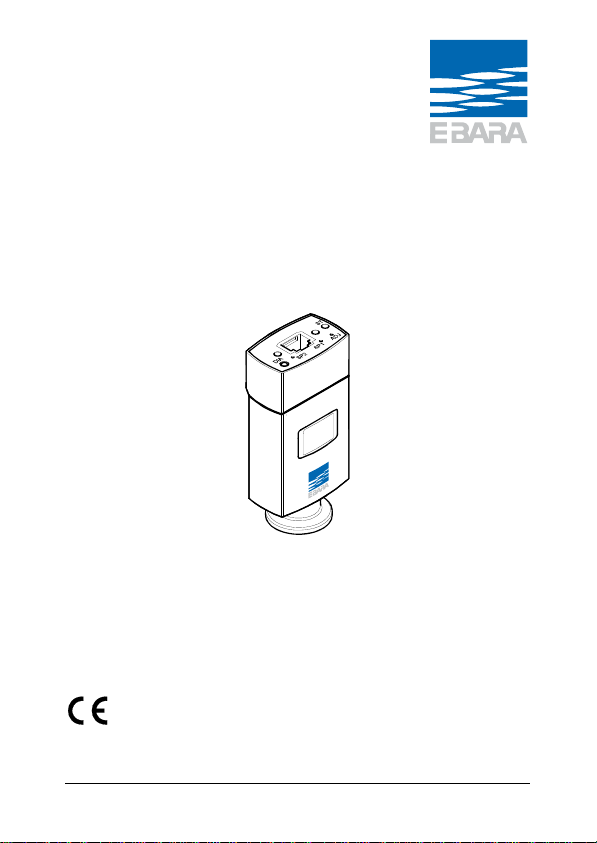
Pirani/Capacitance Gauge
EGPC550
EGPC552
trna56e1 (2012-07) 1
Instruction Manual
Page 2
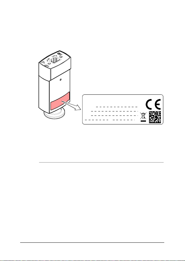
Product Identification
In all communications with EBARA, please specify the information given on the product nameplate. For convenient reference copy that information into the space provided below.
EBARA Technologies, Inc. USA
Model:
PN:
SN:
V W
Validity
This document applies to products with the following part numbers:
EGPC550 (W filament)
EGPC550-0000
EGPC550-0004
EGPC550-0104
EGPC550-0204
EGPC550-1000
EGPC550-1004
EGPC550-1104
EGPC550-1204
2
DN 16 ISO-KF, w/o display, mbar
DN 16 ISO-KF, with two switching functions
and display, mbar
DN 16 ISO-KF, with two switching functions
and display, Torr
DN 16 ISO-KF, with two switching functions
and display, Pa
DN 16 CF-F, w/o display, mbar
DN 16 CF-F, with two switching functions and
display, mbar
DN 16 CF-F, with two switching functions and
display, Torr
DN 16 CF-F, with two switching functions and
display, Pa
trna56e1 (2012-07)
Page 3

EGPC552 (Ni filament)
EGPC552-0000
EGPC552-0004
EGPC552-0104
EGPC552-0204
EGPC552-1000
EGPC552-1004
EGPC552-1104
EGPC552-1204
DN 16 ISO-KF, w/o display, mbar
DN 16 ISO-KF, with two switching functions
and display, mbar
DN 16 ISO-KF, with two switching functions
and display, Torr
DN 16 ISO-KF, with two switching functions
and display, Pa
DN 16 CF-F, w/o display, mbar
DN 16 CF-F, with two switching functions and
display, mbar
DN 16 CF-F, with two switching functions and
display, Torr
DN 16 CF-F, with two switching functions and
display, Pa
The part number (PN) can be taken from the product nameplate.
If not indicated otherwise in the legends, the illustrations in this
document correspond to gauges with part number
EGPC550-0004. They apply to gauges with other part numbers
by analogy.
We reserve the right to make technical changes without prior
notice.
All dimensions in mm.
Intended Use
The Pirani/Capacitance Gauge EGPC55x has been designed for
vacuum measurement of gases in the pressure range of
-5
5×10
… 1500 mbar.
It must not be used for measuring flammable or combustible
gases in mixtures containing oxidants (e.g. atmospheric oxygen)
within the explosion range.
The gauge is intended for operation in connection with an
EBARA Vacuum Gauge Controller (e.g. EGC) or with another
suitable controller.
trna56e1 (2012-07) 3
Page 4

Functional Principle
The EGPC gauge is a combination gauge consisting of a Pirani
sensor and a diaphragm capacitive sensor. Both sensors are
constantly active.
At low pressures, only the signal of the Pirani sensor is used for
pressure measurement; at high pressures, only the signal of the
diaphragm capacitive sensor. To determine the output signal in
the intermediate range, both signals are used proportionally to
the pressure.
Patents
EP 0689669 B1, 0689670 B1, 0658755 B1
US Patents 5608168, 4031997, 5583297
Scope of Delivery
1× gauge
1× pin for adjusting settings via buttons
1× Instruction Manual
4
trna56e1 (2012-07)
Page 5

Contents
Product Identification 2
Validity 2
Intended Use 3
Functional Principle 4
Patents 4
Scope of Delivery 4
1 Safety 6
1.1 Symbols Used 6
1.2 Personnel Qualifications 6
1.3 General Safety Instructions 7
1.4 Liability and Warranty 7
2 Technical Data 8
2.1 Output Signal vs. Pressure 12
2.2 Gas Type Dependence 13
3 Installation 14
3.1 Vacuum Connection 14
3.2 Power Connection 17
4 Operation 19
4.1 Status Indication and Display 19
4.2 Gas Type Dependence 23
4.3 Switching Functions 24
5 Deinstallation 26
6 Maintenance, Repair 28
6.1 Adjusting the Gauge 28
6.2 Replacing the Sensor 30
6.3 Troubleshooting 31
7 Returning the Product 32
8 Disposal 33
9 Spare Parts 34
Further Information 35
For cross-references within this document, the symbol ( XY)
is used, for cross-references to further documents, listed under
"Further Information", the symbol ( [Z]).
trna56e1 (2012-07) 5
Page 6
1 Safety
1.1 Symbols Used
DANGER
Information on preventing any kind of physical injury.
WARNING
Information on preventing extensive equipment and environmental damage.
Caution
Information on correct handling or use. Disregard can lead to
malfunctions or minor equipment damage.
Notice
<…> Labeling
1.2 Personnel Qualifications
Skilled personnel
All work described in this document may only be carried out by
persons who have suitable technical training and the necessary experience or who have been instructed by the end-user
of the product.
6
trna56e1 (2012-07)
Page 7

1.3 General Safety Instructions
Adhere to the applicable regulations and take the necessary
precautions for the process media used.
Consider possible reactions with the product materials.
Consider possible reactions (e.g. explosion) of the process
media due to the heat generated by the product.
Adhere to the applicable regulations and take the necessary
precautions for all work you are going to do and consider the
safety instructions in this document.
Before beginning to work, find out whether any vacuum com-
ponents are contaminated. Adhere to the relevant regulations
and take the necessary precautions when handling contaminated parts.
Communicate the safety instructions to all other users.
1.4 Liability and Warranty
EBARA assumes no liability and the warranty becomes null and
void if the end-user or third parties
disregard the information in this document
use the product in a non-conforming manner
make any kind of interventions (modifications, alterations etc.)
on the product
use the product with accessories not listed in the product
documentation.
The end-user assumes the responsibility in conjunction with the
process media used.
Gauge failures due to contamination or wear and tear, as well as
expendable parts (e.g. seals, filament), are not covered by the
warranty.
trna56e1 (2012-07) 7
Page 8

2 Technical Data
Measurement range 5×10⁻⁵ … 1500 mbar
Measurement principle
10 mbar … 1500 mbar
1 … 10 mbar crossover range
-5
… 1 mbar thermal conductance acc. to
5×10
Accuracy (N
5×10
1×10
)
2
-4
… 1×10⁻³ mbar
-3
… 100 mbar
100 … 950 mbar
950 … 1050 mbar
Repeatability (N
1×10
)
2
-3
… 1100 mbar
Output signal (measurement signal)
Voltage range 0 … +10.23 V
Measurement range +0.61 … +10.23 V
Error signal 0 V (default)
Voltage vs. pressure 1.286 V/decade, logarithmic
Output impedance
Load impedance
Response time
Gauge identification
HV adjustment
ATM adjustment at >100 mbar
diaphragm capacitive
sensor
Pirani
50% of reading
15% of reading
5% of reading
2.5% of reading
2% of reading
2 × 4.7 , short circuit-proof
>10 k
<30 ms
71.5 k
at 10
-5
mbar
8
trna56e1 (2012-07)
Page 9
Switching functions SP1, SP2
Setting range (N
) 5.0×10⁻⁵ … 1500 mbar
2
Hysteresis 10% of threshold
Switching characteristics Low Trip Point
Type 1 floating contact (n.o.) per
switching function
Contact rating <30 VAC/DC, ≤1 A
resistive
closed LED lit solid
open LED off
Switching time <30 ms
Supply
DANGER
The gauge may only be connected to power supplies, instruments, or control devices that conform
to the requirements of a grounded protective extralow voltage (SELV). The connection to the gauge
has to be fused.
1)
Supply voltage at the gauge +15 … +30 VDC
Ripple ≤1 V
Power consumption ≤2.5 W
Fuse to be connected
1)
1 AT
pp
Electrical connection FCC68
Sensor cable shielded
0.14 mm
2
/conductor
Cable length ≤100 m
1)
EBARA controllers fulfill this requirement.
trna56e1 (2012-07) 9
Page 10

Grounding concept
Vacuum connection to
signal common
"Power Connection"
connected via 10 k, 10 nF
Materials exposed to vacuum
Vacuum connection
Filament
EGPC550
EGPC552
Feedthrough
Orifice
Diaphragm
Further materials
stainless steel 1.4435
W
Ni
glass
stainless steel
ceramic
Ni, NiFe, stainless steel
1.4301, SnAg
Internal volume 4.7 cm
3
Permissible pressure (absolute) ≤5 bar
Bursting pressure (absolute) 10 bar
Permissible temperatures
Operation
Vacuum connection
Filament
Storage
Relative humidity
Year's mean
During 60 days
2)
+10 °C … +50 °C
≤80 °C
<160 °C
–20 °C … +65 °C
≤65% (no condensation)
≤85% (no condensation)
Mounting orientation any
Use indoors only, altitude up to
2000 m NN
Degree of protection IP 40
Weight 115 g …130 g
2)
For horizontal mounting orientation only. During bakeout,
measurement range, accuracy, and repeatability may deviate from
specifications.
10
trna56e1 (2012-07)
Page 11
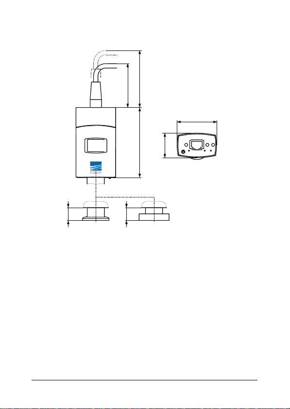
Dimensions [mm]
65
50
45
ST
SP1SP2
ADJ
14.5
DN 16 ISO-KF
79.5
14
DN 16 CF-R
28
DIA
trna56e1 (2012-07) 11
Page 12

2.1 Output Signal vs. Pressure
Pressure p
1E+06
1E+05
1E+04
1E+03
1E+02
1E+01
Error
1E+00
1E–01
1E–02
1E–03
1E–04
1E–05
0.5
0.0
p = 10
Underrange
3.02.52.01.51.0
0.61
0.778(U-c)
4.03.5 5.04.5 6.05.5 7.06.5 8.07.5 9.08.5 10.09.5 10.5
Output signal U [V]
U = c +1.286log10 p
valid in the range 5×10⁻⁵ mbar <p< 1500 mbar
U p c U p c
[V] [mbar] 6.143 [V] [micron] 2.448
[V] [µbar] 2.287 [V] [Pa] 3.572
[V] [Torr] 6.304 [V] [kPa] 7.429
[V] [mTorr] 2.448
where p pressure
U output signal
c constant (pressure unit dependent)
Pa
mbar
Torr
Overrange
O
12
trna56e1 (2012-07)
Page 13

2.2 Gas Type Dependence
Indicated pressure (gauge calibrated for air)
p [mbar]
4
2
3
10
8
6
4
2
2
10
8
6
4
2
1
10
8
6
4
2
0
10
8
6
4
2
–1
10
8
6
4
2
–2
10
8
6
4
2
–3
10
8
6
4
2
–4
10
–4
–3
246
10
246
10
Calibration factors
valid for Pirani pressure range below 1 mbar
p
= C × indicated pressure
Gas type Calibration
He
Ne
Ar
Kr
Xe
eff
factor C
0.8
1.4
1.7
2.4
3.0
Pirani
sensor
–2
–1
246246
10
10
Gas type Calibration
H
Crossover
range
0
246
10
10
2
air, O2, CO, N
CO2
water vapor
Freon 12
Capacitive
diaphragm
sensor
Air, O2, CO, N
He
Ar
1
246
10
2
2
2
246
factor C
p
0.5
1.0
0.9
0.5
0.7
10
[mbar]
eff
3
2
trna56e1 (2012-07) 13
Page 14

3 Installation
WARNING
WARNING: fragile components
The ceramic sensor may be damaged by impacts.
Do not drop the product and prevent shocks and
3.1 Vacuum Connection
impacts.
DANGER
DANGER: overpressure in the vacuum system
>1 bar
Injury caused by released parts and harm caused
by escaping process gases can result if clamps are
opened while the vacuum system is pressurized.
Do not open any clamps while the vacuum system
is pressurized. Use the type clamps which are
suited to overpressure.
14
DANGER: overpressure in the vacuum system
>2.5 bar
KF flange connections with elastomer seals (e.g.
O-rings) cannot withstand such pressures. Process
media can thus leak and possibly damage your
health.
Use O-rings provided with an outer centering ring.
DANGER
trna56e1 (2012-07)
Page 15

DANGER: protective ground
Products that are not correctly connected to ground
can be extremely hazardous in the event of a fault.
Electrically connect the gauge to the grounded
vacuum chamber. This connection must conform to
the requirements of a protective connection according to EN 61010:
CF flanges fulfill this requirement.
For gauges with a KF flange, use a conductive
metallic clamping ring.
Caution: vacuum component
Dirt and damages impair the function of the vac-
uum component.
When handling vacuum components, take appro-
priate measures to ensure cleanliness and prevent
damages.
Caution: dirt sensitive area
Touching the product or parts thereof with bare
hands increases the desorption rate.
Always wear clean, lint-free gloves and use clean
tools when working in this area.
DANGER
Caution
Caution
trna56e1 (2012-07) 15
Page 16

Mount the gauge so that no vibrations occur. The gauge
may be mounted in any orientation. To keep condensates and particles from getting into the measuring
chamber preferably choose a horizontal to upright position and consider using a seal with centering ring and
filter. If adjustment should be possible after the gauge
has been installed, be sure to install it so that the buttons can be accessed with a pin.
Remove the protective lid and connect the product to the
vacuum system.
Seal with centering ring
16
Clamp
Keep the protective lid.
or
Protective lid
Seal with centering
ring and filter
trna56e1 (2012-07)
Page 17

3.2 Power Connection
Make sure the vacuum connection is properly made
( 14).
DANGER
The gauge may only be connected to power supplies, instruments or control devices that conform
to the requirements of a grounded protective extralow voltage (SELV). The connection to the gauge
has to be fused.
3)
Ground loops, differences of potential, or EMC problems
may affect the measurement signal. For optimum signal
quality, please do observe the following notes:
Connect the cable shield to ground on one side via
the connector housing. Do not connect the other side
of the shield.
Connect the supply common with protective ground
directly at the power supply.
Use differential measurement input (signal common
and supply common conducted separately).
Potential difference between supply common and
housing ≤18 V (overvoltage protection).
3)
EBARA controllers fulfill these requirements.
trna56e1 (2012-07) 17
Page 18

If no sensor cable is available, make one according to the
following diagram. Connect the sensor cable.
Ident
+
–
Measurement
signal
Supply
4.7
4.7
SP2
SP1
4
6
8
7
3
5
+24V
18V
10k
10nF
Electrical connection
Pin 1 Supply
Pin 2 Supply common, GND
Pin 3 Measurement signal
or threshold SP1, SP2
Pin 4 Gauge identification
Pin 5 Signal common
Pin 6, 8 Relay SP2
Common closing contact (com)
Pin 7, 8 Relay SP1
Common closing contact (com)
18
1
2
1
8
8-pin
FCC68
connector
trna56e1 (2012-07)
+
–
Page 19

4 Operation
When the supply voltage is applied, the measurement signal is
available at the connector ( "Power Connection").
Allow a stabilization period of at least 10 minutes. It is advisable
to operate the gauge continuously, irrespective of the pressure.
The gauge is factory calibrated. Due to long time operation or
contamination, a zero drift could occur. Periodically check the
zero and adjust it if necessary (adjusting the gauge 28).
4.1 Status Indication and Display
Light-emitting diodes (LEDs)
For factory setting only
ST
DIA
SP1SP2
LED State Meaning
<ST> off no supply voltage
lit green measurement mode
lit red error
<SP1> lit green Relay SP 1 closed
off Relay SP 1 open
<SP2> lit green Relay SP 2 closed
off Relay SP 2 open
Status
ADJ
trna56e1 (2012-07) 19
Page 20

Liquid crystal display (LCD)
LCD Meaning
off no supply voltage
lit green measurement / parameter mode
lit red error
Put the gauge into operation
When the supply voltage is applied
the software version is briefly
displayed.
20
trna56e1 (2012-07)
Page 21

Measurement mode
Relay 2
Status of Relay 2
Relay 1
Status of Relay 1
Measurement
principle
Output signal
Setpoint
open
closed
Setpoint
open
closed
Pirani
Capacitive
Crossover range
Unit
Millibar
Torr
Pascal
Micron
(no display)
Counts
Underrange
Overrange
(no display)
trna56e1 (2012-07) 21
Within range
Page 22

Parameter mode
Switching functions <S>
When the <SP1> or <SP2> button is
pushed, the corresponding
threshold is displayed and the
corresponding relay flashes.
Threshold
Error display (trouble shooting 31)
Pirani sensor error
22
Diaphragm sensor error
EEPROM error
trna56e1 (2012-07)
Page 23

Sensor error
4.2 Gas Type Dependence
Pressure range Measurement
Gas type dependence
principle
10 … 1500 mbar
diaphragm
capacitive sensor
independent of gas
type, no correction
required
1 … 10 mbar
5×10⁻⁵ … 1 mbar Pirani sensor proportional to
diaphragm
capacitive sensor
and Pirani sensor
crossover range
)
4
pressure
4)
The pressure reading applies to dry air, O2, CO and N2. For other
gases, it has to be converted (calibration factors ( 13).
trna56e1 (2012-07) 23
Page 24

4.3 Switching Functions
The two switching functions can be set to any pressure within
the measurement range of the gauge. A mechanical relay is
provided for each switching function.
The current threshold setting is output at the measurement
signal output instead of the pressure signal, can be measured
with a voltmeter, and is displayed on the LCD after the <SP1> or
<SP2> button is pressed
The setpoints SP1 and SP2 are factory set to the lower measurement range limit and therefore do not switch.
Measurement signal
(Pressure p)
n
e
m
e
r
u
s
a
e
M
Setpoint
Hysteresis
(10% of threshold)
Threshold value
e
u
l
a
v
t
Time t
Off
OffOn
If the pressure in the vacuum system is lower than the setpoint,
the corresponding LED (<SP1> or <SP2>) is lit solid and the
corresponding relay is closed.
The upper threshold is 10% above the lower one
(hysteresis).
24
trna56e1 (2012-07)
Page 25

4.3.1 Adjusting the Setpoints
DANGER
DANGER: malfunction
If processes are controlled via the signal output,
keep in mind that by pushing an <SP> button the
measurement signal is suppressed and the corresponding threshold value is output instead. This
can cause malfunctions.
Push the <SP> button only if you are sure that no
damages can arise from a malfunction.
Adjusting setpoint SP1 with button on the gauge
Push the <SP1> button with a pin (max. ø1.1 mm). The
gauge changes to the switching function mode and outputs
the current threshold value at the measurement value output or on the LCD for about 5 s and the corresponding <S>
on the display blinks.
The threshold setting is increased towards the upper limit
until the button is released or the limit is reached.
Keep the button
depressed
trna56e1 (2012-07) 25
Page 26

Push the <SP1> button again:
Fine adjustment
within 0...1 s:
Change of direction
within 2...3 s:
the threshold value changes by one
unit
the threshold adjustment changes
its direction
The <SP1> button is released for more than 5 s: the
threshold value is saved and the gauge returns to the
measurement mode.
The adjustment procedure for <SP2> is the same as for setpoint
SP1.
5 Deinstallation
WARNING
WARNING: fragile components
The ceramic sensor may be damaged by impacts.
Do not drop the product and prevent shocks and
impacts.
26
DANGER: contaminated parts
Contaminated parts can be detrimental to health
and environment.
Before beginning to work, find out whether any
parts are contaminated. Adhere to the relevant
regulations and take the necessary precautions
when handling contaminated parts.
DANGER
trna56e1 (2012-07)
Page 27

Caution
Caution: vacuum component
Dirt and damages impair the function of the vac-
uum component.
When handling vacuum components, take appro-
priate measures to ensure cleanliness and prevent
damages.
Caution
Caution: dirt sensitive area
Touching the product or parts thereof with bare
hands increases the desorption rate.
Always wear clean, lint-free gloves and use clean
tools when working in this area.
Vent the vacuum system.
Put the gauge out of operation.
Disconnect the sensor cable.
Remove gauge from the vacuum system and install the
protective lid.
trna56e1 (2012-07) 27
Page 28

Protective lid
6 Maintenance, Repair
Gauge failures due to contamination or wear and tear,
as well as expendable parts (e.g. seals, filament), are
not covered by the warranty.
EBARA assumes no liability and the warranty becomes null and
void if any repair work is carried out by the end-user or third
parties.
6.1 Adjusting the Gauge
The gauge is factory calibrated. Due to long time operation or
contamination, a zero drift could occur. Periodically check the
zero and adjust it if necessary.
For adjusting the zero, operate the gauge under the same constant ambient conditions and in the same mounting orientation
as normally.
The gauge is adjusted to default values. However, it can also be
adjusted to other pressure values, if the exact pressure value is
known (reference measurement).
28
trna56e1 (2012-07)
Page 29

If you are using a seal with centering ring and filter, check
that they are clean or replace them if necessary
( "Deinstallation").
Put the gauge into operation and operate it at atmospheric
pressure for at least 10 minutes.
Press the <ADJ> button with a pin (max. ø1.1 mm) and the
ATM adjustment is carried out: The gauge is adjusted to
1000 mbar by default. By pressing the button >5 s the
pressure value is increased towards 1200 mbar (or, by
pressing it again, decreased towards 500 mbar) until the
button is released or the limit is reached.
ATM
HV
Evacuate the vacuum system to p << 10
least 2 minutes.
-5
mbar and wait at
Press the <ADJ> button with a pin and the HV adjustment
is carried out: The gauge is adjusted to 5×10
(default).
If the pressure value 4.99×10⁻⁵ mbar is output at the meas-
urement value output or on the LCD, the adjustment has
been successful. Otherwise, repeat the adjustment procedure.
trna56e1 (2012-07) 29
-5
mbar
Page 30

6.2 Replacing the Sensor
In case of severe contamination or a malfunction, the sensor can
be replaced.
Precondition
Gauge deinstalled ( 26).
Unscrew the hexagon socket screws and remove the sen-
sor without twisting it.
2 mm
Place the new sensor without twisting it and lock it with the
screws.
30
trna56e1 (2012-07)
Page 31

6.3 Troubleshooting
In case of an error, it may be helpful to just turn off the
mains supply and turn it on again after 5 s.
Problem Possible cause Correction
Output signal permanently 0V
No supply voltage Turn on the power supply
Error Remedy the error
Gauge in an undefined status Turn the gauge off and on
FAIL PIR1 Pirani sensor defective Replace the sensor
Electronics unit not correctly
FAIL CAP1 Diaphragm sensor defective Replace the sensor
Electronics unit not mounted
FAIL EEPROM EEPROM error Turn the gauge off and on
Replace the gauge
FAIL SENSOR Electronics unit not compatible
Replace the gauge
Sensor cable defective or not
correctly connected
mounted on sensor
correctly on sensor
with the sensor
Check the sensor cable
again after 5 s (reset)
( 30)
Check the connections
(electronics – sensor)
( 30)
Check the connections
(electronics – sensor)
again after 5 s (reset)
Replace the sensor
( 30)
trna56e1 (2012-07) 31
Page 32

7 Returning the Product
WARNING
WARNING: forwarding contaminated products
Contaminated products (e.g. radioactive, toxic,
caustic or microbiological hazard) can be detrimental to health and environment.
Products returned to EBARA should preferably be
free of harmful substances. Adhere to the forwarding regulations of all involved countries and forwarding companies and enclose a duly completed
declaration of contamination (form under
Products that are not clearly declared as "free of harmful substances" are decontaminated at the expense of the customer.
Products not accompanied by a duly completed declaration of
contamination are returned to the sender at his own expense.
www.ebaratech.com).
32
trna56e1 (2012-07)
Page 33

8 Disposal
DANGER
DANGER: contaminated parts
Contaminated parts can be detrimental to health
and environment.
Before beginning to work, find out whether any
parts are contaminated. Adhere to the relevant
regulations and take the necessary precautions
Separating the components
After disassembling the product, separate its components according to the following criteria:
Contaminated components
Other components
when handling contaminated parts.
WARNING
WARNING: substances detrimental to the environment
Products or parts thereof (mechanical and electric
components, operating fluids etc.) can be detrimental to the environment.
Dispose of such substances in accordance with the
relevant local regulations.
Contaminated components (radioactive, toxic, caustic or biological hazard etc.) must be decontaminated in accordance
with the relevant national regulations, separated according to
their materials, and disposed of.
Such components must be separated according to their materials and recycled.
trna56e1 (2012-07) 33
Page 34

9 Spare Parts
When ordering spare parts, always indicate:
all information on the product nameplate
description and ordering number
Sensor for gauges with tungsten (W) filament Ordering No.
EGPC550-0000
EGPC550-0004
EGPC550-0104
EGPC550-0204
EGPC550-1000
EGPC550
EGPC550-1004
EGPC550-1104
EGPC550-1204
Sensor for gauges with nickel (Ni) filament Ordering No.
EGPC552-0000
EGPC552-0004
EGPC552-0104
EGPC552-0204
EGPC552-1000
EGPC552
EGPC552-1004
EGPC552-1104
EGPC552-1204
DN 16 ISO-KF
DN 16 CF-F
DN 16 ISO-KF
DN 16 CF-F
EGPC550-P001
EGPC550-P002
EGPC552-P001
EGPC552-P002
34
trna56e1 (2012-07)
Page 35

Further Information
[1] www.ebaratech.com
Instruction Manual
Single-Channel Controller
EGC-1000
EBARA Technologies, Sacramento, CA 95838, USA
[2] www.ebaratech.com
Instruction Manual
Three-Channel Controller
EGC-3000
trnb07e1
EBARA Technologies, Sacramento, CA 95838, USA
trna56e1 (2012-07) 35
Page 36

EBARA Technologies Incorporated
51 Main Avenue Sacramento, CA 95838, US A
Phone: 1-916-920-5451 − Fax: 1-916-830-6654
www.ebaratech.com
Original: English trna56e1 (2012-07)
t r na56e1
 Loading...