

EATON TRSM4106 Service Manual

Service Manual
Fuller Mid Range Transmissions
TRSM4106
October 2007

Eaton 6-Speed Synchromesh Transmission
Truck Components Operations Europe
PO Box 11 Worsley
Manchester M28 5GJ
England
Service Manual
(4106 / 5206)

Section 1 General
1/1 Letter and Model Designation
1/2 Technical Data
1/3 Lubrication
1/4 Recommended Lubricants
1/5 Torque Tightening Recommendations
1/7 Disassembly Precautions and Inspection of Expendable Parts
1/9 Reassembly Precautions
1/10 Gear End Floats
1/11 Special Tools
1/14 Locally Made Tools
Section 2 General Discription
2/1 Features
2/2 Gear Change Pattern
2/2 Power Flow Diagrams
Section 3 Shifting Controls
3/2 Remote Control - Exploded View
3/3 Remote Control Disassembly
3/4 Remote Control Reassembly
3/7 Direct Control - Exploded View
3/8 Direct Control Disassembly
3/9 Direct Control Reassembly
Section 4 Transmission Overhaul
4/2 Transmission Case - Exploded View
4/3 Transmission Case Disassembly
4/9 Layshaft Disassembly
4/10 Layshaft Reassembly
4/11 Synchroniser Flange Removal / Fitment
4/12 Maninshaft Disassembly (New Type)
4/13 Maninshaft Reassembly (New Type)
4/17 Mainshaft Assembly - Exploded View (NewType)
4/31 Mainshaft Disassembly (Old Type)
4/32 Mainshaft Assembly - Exploded View (Old Type)
4/35 Mainshaft Reassembly (Old Type)
4/41 Selector Shaft Disassembly
4/42 Selector Shaft Reassembly
4/44 Transmission Case Reassembly
5/01
Section 2 General
5/01

General
Model Designation
Example: FSO-4106A
FS Standard prefix
O Overdrive
4 Nominal torque in 00 lbs ft
1 Series 1
06 Number of forward gears
A Standard ratio set
B, C Alternative ratio sets
Transmission Identification
All transmissions are fitted with an identification plate on the left hand side of the front case showing
1. Transmission serial number.
2. Transmission model.
3. Manufacturing data code.
4. Transmission specification number.
The transmission specification number is unique to each customer and gives precise details of the transmission design level. This number must be quoted when ordering replacement parts.
There are currently two design levels of the 4106 transmission. Each level is identified by the specification number.
Y 0400
Y 04100
The middle digit denotes the design level.
1/1
5/01

General
Technical Data
Models FS-4106A, FS-4106B, FS-5206A, FS(O)-5206B
Nominal Input Torque
FS-4106A
FS-4106B
FS-5206A
FS(O)-5206B
640 Nm
650 Nm
700 Nm
700 Nm
Weight 1)
Length 2)
Oil capacity
Vertical
Horizontal
Clutch Housing
Power Take-off Openings
PTO Drive Gears 3)
driven from the reverse idler gear at:
FS-4106A, FS-5206A
FS-4106B, FS-5206B
FS-4106B, FS(O)-5206B
driven from layshaft front gear at:
FS-4106A, FS-5206A
FS-4106B, FS-5206B
FS-4106B, FS(O)-5206B
115 kg
520 mm
7,5 lit
6,5 lit
SAE Standard
Left side (vertical installation), bottom right
(horizontal installation): 2 SAE 6 bolt facings
plus extended layshaft for Eaton PTO
Rotation to Engine
engine speed x
0,226 Same
0,271
0,336
engine speed x
0,434 Opposite
0,519
0,644
Gear
6
5
4
3
2
1
Reverse
1) including output coupling, low remote control; less clutch housing
2) front face of transmission case to rear face of output flange
3) recommended backlash is from 0.15 to 0.25mm.
FS-4106A
FS-5206A
1.00
__
1.38
__
2.00
__
3.10
__
5.25
__
9.03
__
8.07
%
Step
38
45
55
69
72
FS-4106B
FS-5206B
1.00
__
1.29
__
1.86
__
2.80
__
4.38
__
7.54
__
6.74
%
Step
26
43
50
57
72
FS(O)-4106B
FS(O)-5206B
1.00
__
1.37
__
2.12
__
3.56
__
6.08
__
9.03
__
5.43
%
Step
26
37
55
69
72
5/011/2

General
Lubrication
Proper Oil Level
Before checking the oil level or refilling, vehicle should
be on level ground.
Make sure that the oil is level with the filler opening.
Draining Oil
Drain transmission while oil is warn. To drain oil remove
the drain plug at the bottom if case. Clean the drain plug
before re-installing.
Refilling
Clean area round filler plug.
Fill transmission to the level of the filler opening.
The exact amount of oil depends on the
transmission inclination. In every instance, fill to the
level of the filler opening. Do not overfill this causes
oil to be forced out of the case past the mainshaft and
input shaft seals.
Adding Oil
It is recommended that different types and brands of oil
are not intermixed because of possible incompatibility.
Operating Temprature
It is important that the transmission operating temperature does not exceed 120¡C (250¡F) for an extended
period of time. Operating temperatures above 120¡C
(250¡F) cause breakdown of the oil and shorten transmission life.
The following conditions in any combination can cause
operating temperatures of over 120¡C (250¡F):
1. Operating consistently at road speeds
under 32 km/h (20m.p.h.)
2. High engine RPM
3. High ambient temperature
4. Restricted air flow around transmission
5. Exhaust system too close to transmission
6. High horsepower, over-drive operation
7. High power PTO operation for
extensive periods while stationary
High operating temperatures may require more frequent
oil change.
Towing
When towing the vehicle, the propeller shaft between the
axle and transmission must be disconnected.
1/3
5/01

General
Recommended Lubricants
Only use recommended lubricants to ensure smooth running.
Models Temprature RangeGrade
Mild EP Gear Oil
to Specification
MIL-L-2105 or
API-GL-4
Heavy Duty Engine Oil
to Specification
MIL-L-2104C or
MIL-L-46152 or
API-CD
DO NOT use oil additives, friction modifiers or synthetic lubricants.
SAE 80 W
SAE 90 W
SAE 80 W/90
SAE 50
SAE 40
SAE 30
Service Intervals
Lubrication Change and Inspection
Highway Use
First 5000 to 8000 km (3000 to
5000 miles)
Change transmission oil on new units
-26¡C to 21¡C
-12¡C to 37¡C
-26¡C to 38¡C
above -12¡C
above -12¡C
below -12¡C
Every 16000 km (10000 miles)*
Every 80000 km (50000 miles)+
Off Highway
First 30 hours
Every 40 hours *
Every 500 hours
Every 1000 hours +
Remove and clean oil strainer at each oil change.
Transmissions fitted with an oil cooler may additionally be fitted with a filter in the cooler line,
Renew the filter at every oil change.
* Or 2 months, whichever occurs first.
+ Or 12 months, whichever occurs first.
Inspect oil level. Check for leaks
Change transmission oil
Change transmission oil on new units
Inspect oil level. Check for leaks
Change transmission oil when severe dirt conditions exist
Change transmission oil (normal off- highway use)
5/011/4
General
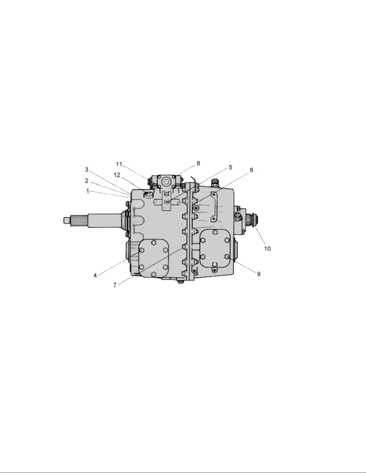
Torque Tightening Recommedations
Screws and Nuts
1. Clutch Housing
12 Studs M12 Thread 59 Nm (43 lbs ft) minimum. Installed with Loctite 242.
2. Clutch Housing
12 Nuts M12 Thread 69 to 78 Nm (51 to 58 lbs ft). With Plain Washers and Spring Lockwashers.
3. Clutch Housing
12 Capscrews M12 Thread 69 to 78 Nm (51 to 58 lbs ft). With Plain Washers and Spring
ockwashers.
4. Front P.T.O. Cover
6 Capscrews M10 Thread 35 to 39 Nm (25 to 29 lbs ft).
5. Selector Block Tapered Lockscrew
1 Lockscrew M10 Thread 35 to 39 Nm (25 to 29 lbs ft). Patchlock or Thread coated with Loctite 270.
6. Main Casing Halves
15 Capscrews with Plain Nuts M10 Thread 51 to 58 Nm (38 to 43 lbs ft). With Plain Washers
under Capscrews and Nuts.
15 Flange headed screws and Nuts M10 Thread 45 to 55 Nm.
7. Main Casing Halves
3 Capscrews M10 Thread 51 to 58 Nm (38 to 43 lbs ft). Plain Washers.
3 Flange headed screws M10 Thread 30 to 40 Nm.
8. Remote Control Housing End Cover
4 Capscrews M8 Thread 20 to 24 Nm (15 to 18 lbs ft). Spring Lockwashers.
9. P.T.O./Reverse Idler Gear Cover
6 Capscrews M10 Thread - 35 to 39 Nm (25 to 29 lbs ft).
10. Output Shaft
Locknut M33 Thread 490 to 588 Nm (362 to 434 lbs ft). With Nylon Locking Insert.
11. Remote Control Housing
4/6/8 Capscrews M10 Thread 35 to 39 Nm (25 to 29 lbs ft). Plain Washers and Spring Lockwashers.
12. Overdrive Selector fork Pivots
2 Capscrews M8 Thread (with lockwashers) 20 to 24 Nm (15 to 18 lbs ft).
1/5
5/01
General
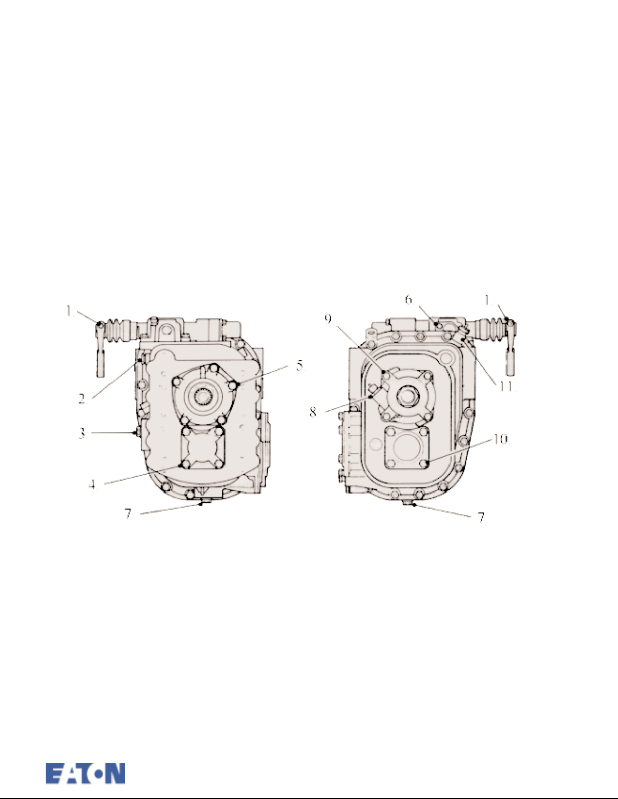
Torque Tightening Recommedations (continued)
Screws and Nuts
1. Remote Control Shaft Lever
1 Capscrew and Nut M10 Thread 35 to 39 Nm (25 to 29 lbs ft). With Spring Lockwasher.
2. Selector shaft Detent Cover
2 Capscrews M8 Thread 20 to 24 Nm (15 to 18 lbs ft). Spring Lockwashers.
3. Oil Filler Plug
M24 Thread 32 to 37 Nm (24 to 27 lbs ft).
4. Layshaft Front Bearing Cover
4 Capscrews M12 Thread 69 to 78 Nm (51 to 58 lbs ft). Spring Lockwashers.
5. Input Shaft Front Bearing Cover
5 Capscrews M10 Thread 35 to 39 Nm (25 to 29 lbs ft). Spring Lockwashers.
6. Remote Control Housing Detent Cover
2 Capscrews M8 Thread 20 to 24 Nm (15 to 18 lbs ft). Lockwashers.
7. Oil Drain Plug (Magnetic)
M24 Thread 32 to 37 Nm (24 to 27 lbs ft).
8. Speedo Pinion Adaptor
M22 Thread 20 to 27 Nm (15 to 20 lbs ft). Copper Washer.
9. Speedometer Housing
4 Capscrews M10 Thread 35 to 39 Nm (25 to 29 lbs ft). Plain Washers and Spring Lockwashers.
10. Layshaft Rear Bearing Cover (Rear P.T.O.)
4 Capscrews M12 Thread 69 to 78 Nm (51 to 58 lbs ft). Spring Lockwashers.
11. Reverse Lamp Switch
M16 Thread 16 to 22 Nm (12 to 17 lbs ft).
5/011/6

General
Disassembly Precautions
It is assumed in the detailed disassembly instructions
that the lubricant has been drained and the necessary
linkage and air lines (if fitted) have been removed from
the chassis.
Removal of the gear shift remote control housing
assembly is included in the detailed instructions; however, this assembly may also be removed from the transmission before removing unit from vehicle.
Follow each procedure closely in each section, making
use of both the text and the pictures.
1. Bearings Carefully wash and relubricate all
bearings as removed and protectively wrap until ready
for use. Remove bearings with pullers designed for this
purpose.
2. Assemblies When disassembling the various
assemblies, such as the mainshaft, layshaft and remote
control housing, lay all parts on a clean bench in the
same sequence as removed. This procedure will simplify reassembly and reduce the possibility of losing parts.
When pulling off synchroniser hubs follow the procedures detailed in Disassembly using a suitable puller of
adequate capacity. Failure to adhere to the recommended procedures may cause irreparable damage.
3. Snap rings Remove snap rings with pliers
designed for this purpose. New selective fit snap rings
must be fitted as specified in Reassembly .
4. Cleanliness Provide a clean place to work.
It is important that no dirt or foreign material enters the
unit during repairs. The outside of the unit should be
carefully cleaned before starting the disassembly. Dirt is
abrasive and can damage bearings.
5. When Pressing Apply force to shafts, housings etc. with restraint. Movement of some parts is
restricted. Do not apply force after the part being driven
stops solidly. Use soft hammers for all disassembly
work.
Do not use pry bars or chisels to separate casing halves
and housings or irreparable damage may be caused.
Inspection of Expendable
Before reassembling the transmission, the individual
parts should be carefully checked to eliminate those
damaged. They should be renewed. This inspection
procedure should be carefully followed to ensure the
maximum wear life from the rebuilt unit.
The cost of a new part is generally a small fraction of
the total cost of downtime and labour, should the use of
a questionable part make additional repairs necessary
before the next regularly scheduled overhaul.
Recommended inspection procedures are set forth in
the following check list.
A. Bearings
1. Wash all bearings in clean solvent. Check rollers
and races for pits and spalled areas. Renew damaged
bearings.
2. Lubricate undamaged bearings and check for axial
and radial clearances. Renew bearings with excessive
clearances.
3. Check fits of bearings in housing bores. If outer
races turn too freely in the bores, the housing should be
renewed. Check housing bores for signs of wear prior
to taking this action. Only replace housing if wear is
seen as a result of bearing spin.
B. Gears
1. Check gear teeth for pitting of the tooth faces.
Gears with pitted teeth should be renewed. Check the
reverse gear dog engagement teeth for freedom from
damage.
2. Check the internal bearing surfaces for wear of the
effects of overheating.
3. Check axial clearances of gears. Where excessive
clearance is found, check gear and hub for excessive
wear.
Maintain the specified axial clearance on mainshaft forward gears.
C. Bearing Sleeve Mainshaft
1. Sleeves with groove formation, pits or which have
either been overheated or worn out must be renewed.
1/7
5/01

General
Inspection of Expendable Parts
D. Synchroniser Assemblies
1. Check to ensure all splines are free from excessive
wear.
2. Check that the engagement dog teeth on the sliding
sleeves, synchroniser rings are free from chipping and
burring.
3. Check that the synchroniser ring cones are not
excessively worn or showing the effects of overheating.
Check the clearance between the synchroniser ring and
the synchroniser flange is between 1.9 mm maximum
and 0.5 mm minimum.
4. Renew the springs, plungers and rollers.
E. Splines
1. Check splines on all shafts for wear. If synchroniser
hubs, output drive flange or clutch hub have worn into
the sides of the splines, the shafts in this condition must
be renewed.
F. Thrust Washers
4. Check condition and fit of selector key and inter-
lock key in shift shaft. Worn or damaged keys must be
renewed.
J. Gear Shift Remove Control
1. Check spring tension on cross shaft. Renew ten-
sion springs if shaft moves too freely.
2. If housing is dismantled, check cross shaft and
inner lever and the bearing bushes for wear. Renew
worn parts.
3. Check all seals and locating journals. Renew worn
parts.
K. Bearing Covers
1. Check covers for wear from thrust. Renew covers
worn or grooved from thrust of bearing outer race.
2. Check bores of covers for wear. Renew those worn
oversize.
L. Oil Return Threads and Seals
1. Check surfaces of all thrust washers. Washers
scored or reduced in thickness should be renewed.
G. Reverse Idler Gear
1. Check bearings and shaft for wear from action of
roller bearings.
H. Clutch Release Parts
1. Check clutch release parts, yokes and bearing car-
rier. Check pedal shafts. Renew worn shafts and bearings.
I. Gear Selector Shaft Assembly
1. Check forks and keys for wear at contact points.
Renew worn parts.
2. Check forks for excessive and uneven wear, renew
worn forks.
3. Check lockscrew in selector block. A lockscrew with
worn taper must be renewed.
1. Check oil seal in front bearing cover for damage and
wear, renew if necessary.
2. Check oil seal in speedometer housing for damage or
wear, renew if necessary. Renew grit shield if worn or
loose on flange.
3. Check oil seal journals for wear and renew if worn or
grooved.
M. O-Rings
1. Renew all O-rings.
5/011/8

General
Reassembly Precautions
Make sure that interiors of all housings are clean. It is
important that dirt be kept out of transmission during
reassembly. Dirt is abrasive and can damage polished
surfaces of bearings and washers. Use certain precautions, as listed below, during reassembly.
1. Gaskets Use new gaskets where detailed only
(neutral detent cover and remote control housing covers). All other locations ensure mating faces are clean
and undamaged and apply a continuous bead of Loctite
518 Flange Sealant to one face only. Do not apply
excessive sealant or allow it to penetrate into the bearings.
2. Capscrews Use thread sealant (Loctite 641) on
all capscrews. The corresponding torque ratings are to
be found in Torque Recommendations for Screws and
Nuts .
3. O Rings Lubricate all O rings lightly with silicone lubricant.
4. Initial Lubrication Lubricate bearings with
gearbox oil during reassembly.
9. Layshaft The layshaft gears are a shrink and
press fit on the layshaft body. The gears must be heated to 150¡C (300¡F) before assembly.
10. Prior to fitting a flange (or yoke) ensure that the
seal track is not grooved, scored or pitted. If in doubt, it
must be replaced.
11. All synchroniser flanges are now loctited to the
gears. It is recommended that this is carried out before
reassembly commences to allow sufficient time for the
Loctite to cure.
5. Axial Clearances Maintain the end float of
mainshaft gears as detailed in the chart on the following
page.
6. Bearings Use of flange-end bearing drivers is
recommended for the installation of bearings. These
drivers apply equal force to both races of the bearing,
preventing damage to balls and races and maintaining
correct bearing alignment with shaft and bore. A tubular
type driver, if used, will apply force only to the inner
race. Heating the bearing inner tracks will aid installation.
7. Output Shaft Drive Flange Tighten the nut to
the correct torque.
8. Synchroniser Hubs All synchroniser hubs are
an interference fit on the mainshaft splines and must be
heated to approximately 85¡C (180¡F) before installation.
1/9
5/01

General
Gear End Floats All dimensions in mm
Gear
Low Limit
High Limit
Tolerance
0,31
0,53
0,22
4th5th (o,d. 6th)
0,35
0,48
0,13
3rd
0,35
0,48
0,13
2nd
0,35
0,48
0,13
1st
0,40
0,57
0,17
Reverse
Sliding
Gear
5/011/10
General
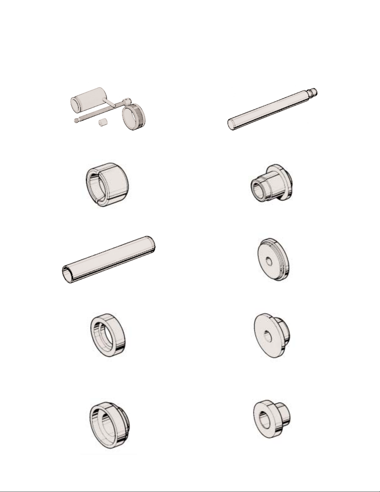
Special Tools
Some illustrations show the use of specialised tools. These tools are recommended for disassembly
and reassembly of the transmission. They make repair easier, faster and prevent damage.
The following tools are available from SPX UK (Ltd) Tel : +44 (0)1327 704461
LC 105A Bearing remover.
E 105-4 Countershaft bearing remover.
E 108 Driver.
E 109 Driver.
E 109-5 Selector control seal and bush installer.
Use with E 109.
E 109-6 Countershaft bearing cup installer adaptor.
Use with E 109.
E 108-5 Replacer adaptor for auxiliary countershaft
bearing and input bearing.
Use with E 108.
E 108-6 Mainshaft rear seal replacer adaptor.
E 109-7 Input shaft seal installer adaptor.
E 109-8 Selector shaft bush installer adaptor.
Use with E 109.
1/11
5/01
General
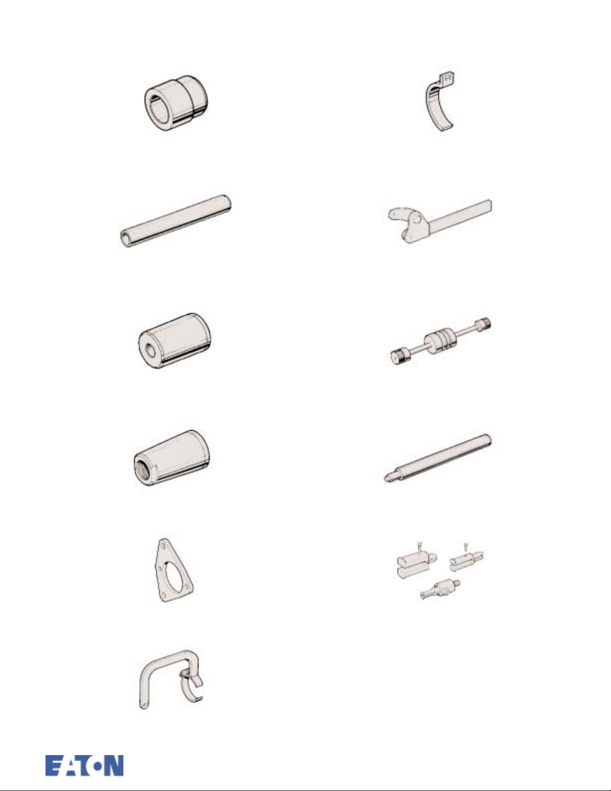
Special Tools (continued)
E 109-9 Selector shaft plug installer adaptor.
Use with E 109.
E 109-10 Driver extension.
Use with E 109.
E 109-11 Countershaft bearing cone installer.
Use with E 109.
E 116-2 Adaptor gear assembly lifting fixture.
Use with E 116A.
LC 113A Flange holding wrench.
MS 284 Slide hammer.
E 114 Rear mainshaft bearing pilot.
E 115 Flange holding adaptor plate
E 116A Gear assembly lifting fixture.
E 117 Reverse idler shaft retaining pin installer.
MS 284-1 Extractor set - bearing/bush.
5/011/12
General
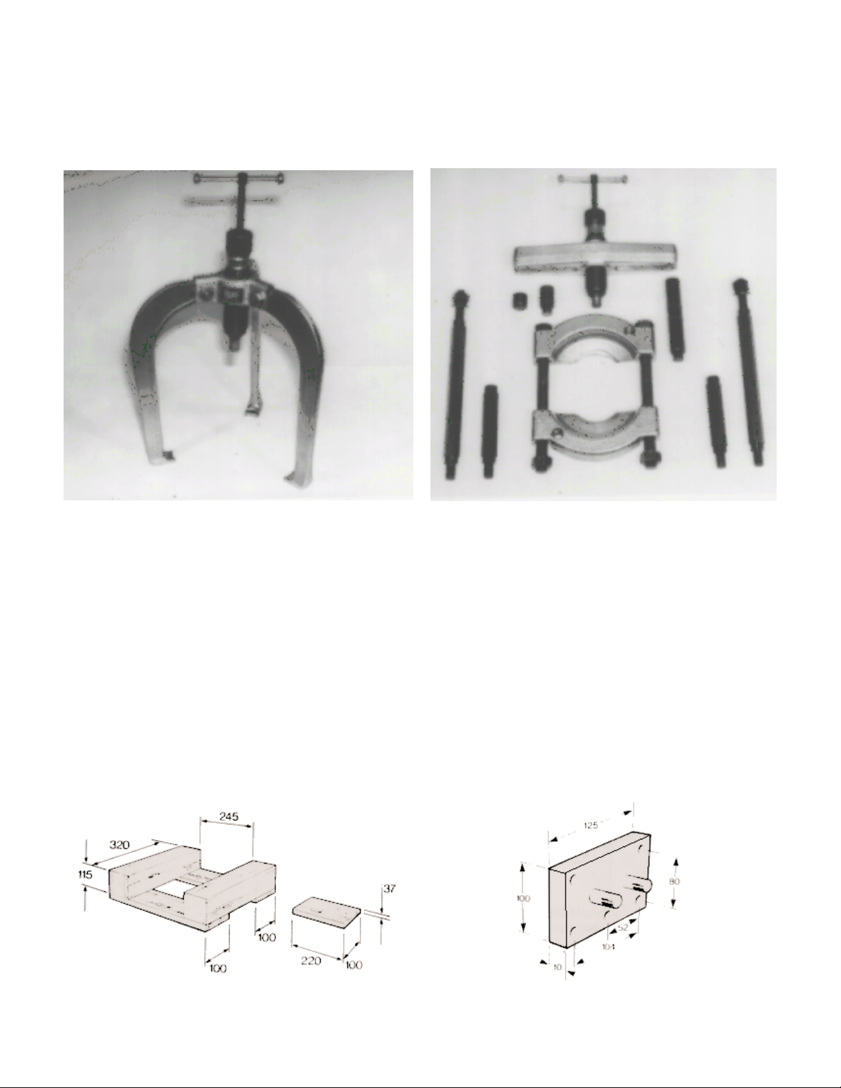
Special Tools (continued)
The following general purpose pullers are available from Sykes-Pickavant Ltd., or through their
Dealers.
Three Legged Puller - Series 1500 with Hydraulic
Ram
Locally Made Tools
The following illustration shows a suitable cradle
which can be used to stand the transmission ’on
end’ during ’Disassembly’ and ’Reassembly’. The
thickness of the block has been calculated to lift
the mainshaft the required distance during removal
and installation of the layshaft. If the height of the
cradle is increasing, the thickness of the block
should be increased by the same amount.
Puller Kit - Series 1500 with Hydraulic Ram
All dimensions in mm.
Mounting Plates - 2 off.
1/13
5/01
General
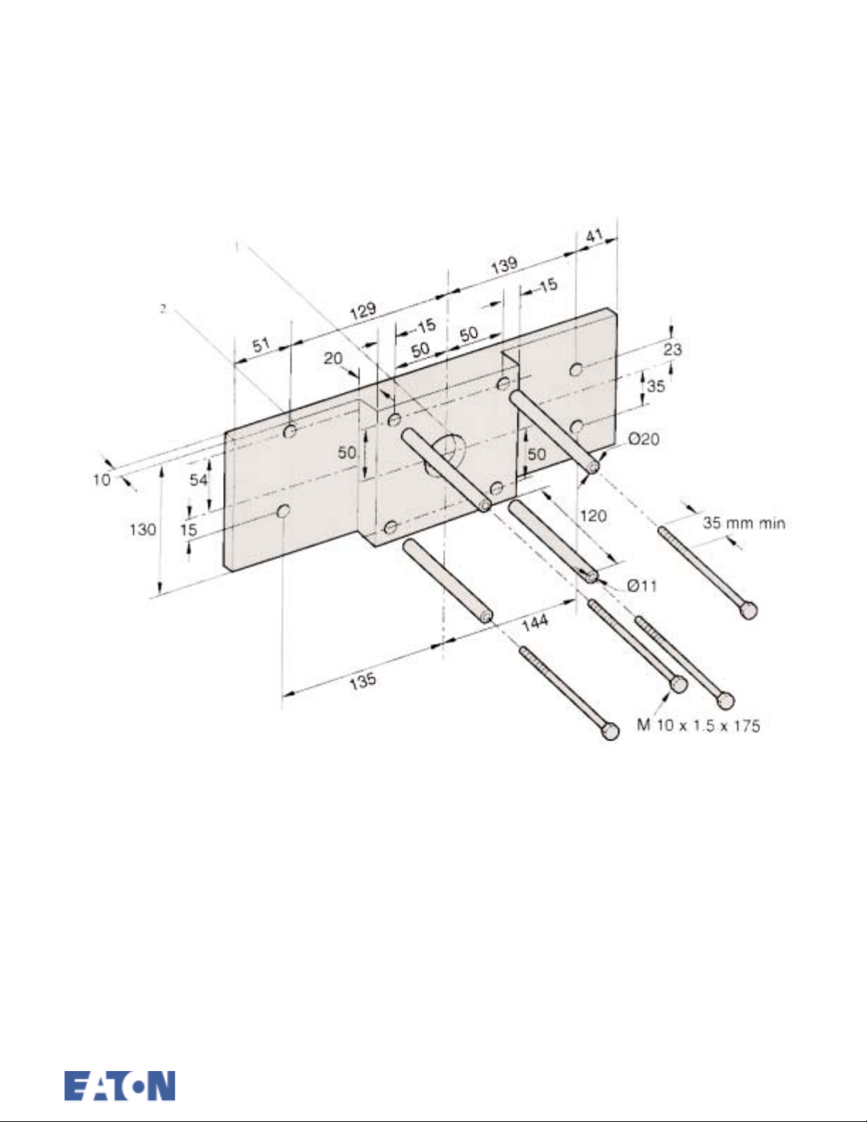
Special Tools (continued)
Locally made tools
1. 1 off hole 1.5 inches diameter 16 threads per
inch Whitworth form to suit Sykes Picavant
hydraulic ram No 150 000.
2. 8 holes 11 mm diameter.
Tool for 4 point ball bearing removal.
5/011/14
2
General
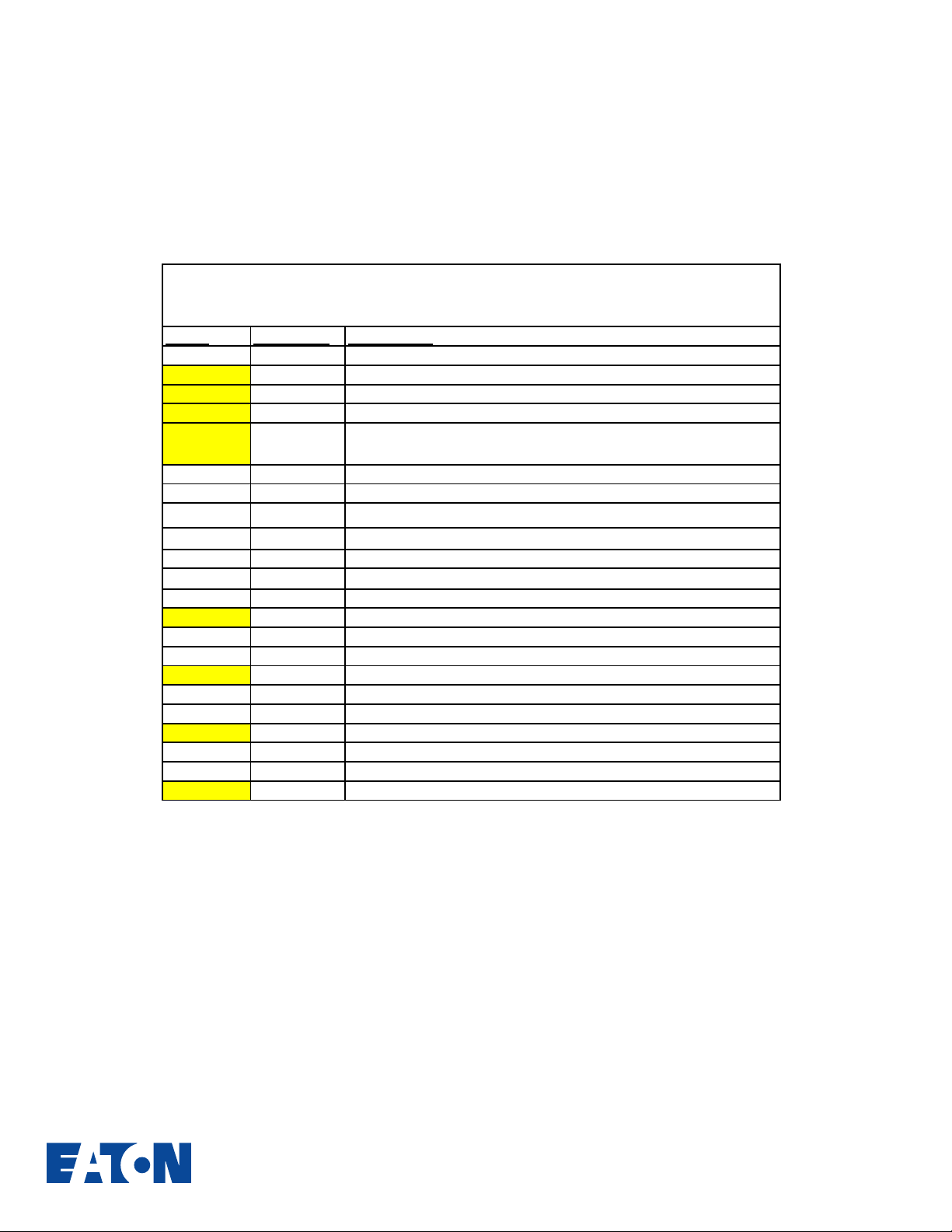
Special Tools for United States
Eaton 4106/5206
SPX # NEW UK # Description
J-45895 LC 105A Bearing Remover
J-45896 E 105-4 Countershaft bearing remover
J-45902 E 108 Driver
Replacer adaptor for auxiliary countershaft bearing and input
J-45897 E 108-5
J 39588 E 108-6 Mainshaft real seal replacer adaptor
J-8092 E 109 Driver
J 39592-1&
J-39587 E 109-6
J-39589 E 109-7 Input shaft seal installer adaptor
J-39585-2 E 109-8
J-39585-1 E 109-9 Selector shaft plug installer adaptor. Use with E109
J-21465-13 E 109-10 Driver extension
J-39586 E 109-11 Countershaft bearing cone installer. Use with E109
J-39590 E 114 Rear mainshaft bearing pilot
J-45899 E 115 Flange holding adaptor plate
J-39584 E 116A Gear assembly lifting fixture
J-39584 E 116-2 Adaptor gear assembly lifting fixture. Use with E116A
J-45898 LC 113A Flange holding wrench
MS284 MS 284 Slide hammer
J-39591 E 117 Reverse idler shaft retaining pin installer
J-45901 MS 284-1 Extractor set - bearing/bush
E 109-5
bearing
Selector control seal and bush installer. Use with E109
Countershaft bearing cup installer adaptor. Use with E109
Selector shaft bush installer adaptor. Use with E109
1/15 5/01

Section 2 General
Description
5/01
General Description
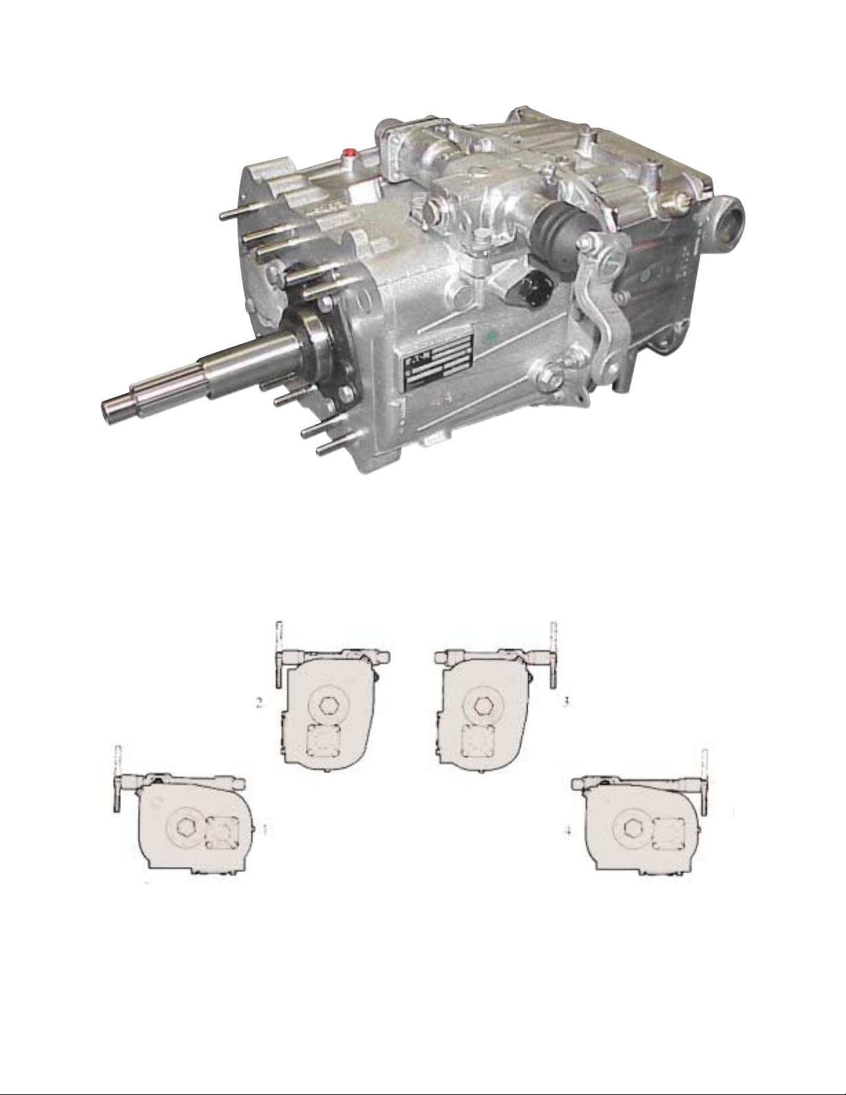
Features
The Eaton six-speed transmissions have six forward speeds and are part of a family of synchromesh
transmissions. They have a simple shift pattern using a unique single rail selector mechanism.
The transmissions may be mounted vertically or horizontally and in both positions the gear change
remote control may be to the right or the left.
1. Left-Hand Horizontal 3. Right-Hand Vertical
2. Left-Hand Vertical 4. Right-Hand Horizontal
The synchroniser assemblies are of the baulk ring type with the gear ring cones manufactured separately
from the gears. This allows the synchroniser rings and flanges to be renewed without the need to renew
the gears themselves. Reverse gear is engaged by sliding the reverse gear on the mainshaft into mesh
with a dog clutch ring splined to the mainshaft.
2/1
5/01
General Description
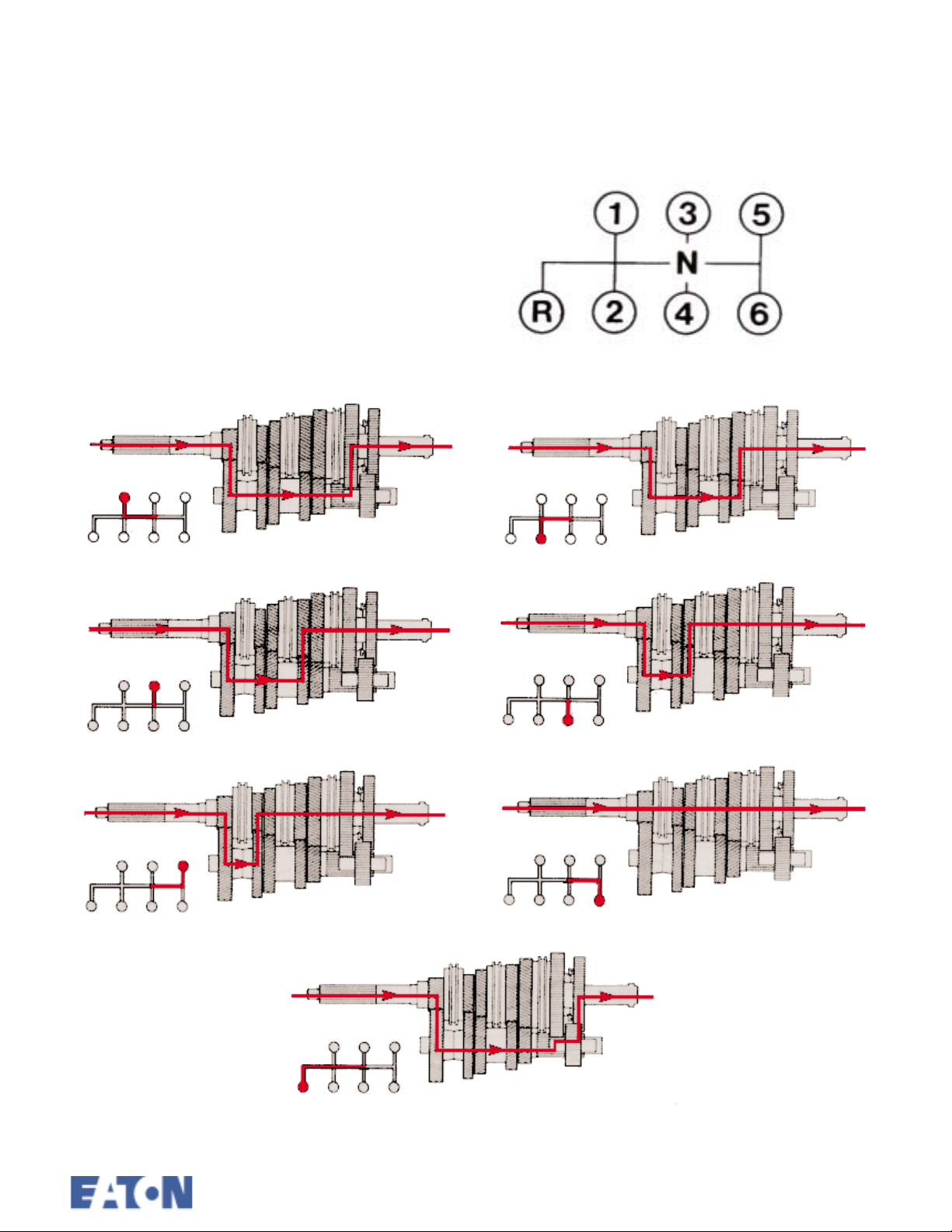
Gear Change Pattern
Simple shift pattern with the mechanism biased
in neutral between 3rd and 4th gears.
1 2
3 4
5 6
R
Power Flow in the Gears - Direct Drive Top Gear Version
5/012/2

Section 3 Shifting
Controls
6 Speed MK.4
3/1
5/01
Shifting Controls
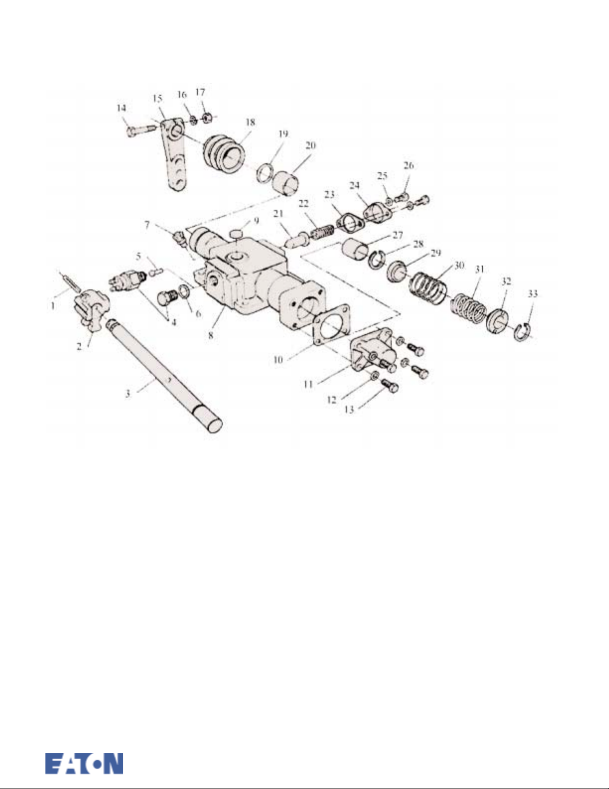
Remote Control - Exploded View
1. Grooved pin
2. Inner striking lever
3. Cross shaft
4. Plug or Neutral switch
5. Pin
6. Washer
7. Breather
8. Housing
9. Plug
10. Gasket
11. End cover
12. Spring washer M8
13. Screw M8
14. Bolt M10 x 50
15. Outer lever
16. Washer
17. Nut M10
18. Boot
19. Oil Seal
20. Bush
21. Reverse plunger
22. Reverse detent spring
23. Detent cover gasket
24. Detent cover
25. Spring washer M8
26. Screw M8
27. Bush
28. Circlip
29. Spring retainer
30. Spring
31. Spring (LH only)
32. Spring retainer
33. Circlip
5/013/2
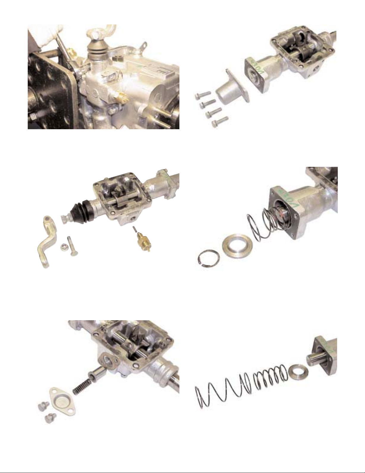
Remote Control Disassembly
1. Ensure neutral is selected and remove the control assembly from the transmission.
2. Remove the outer shift lever and rubber boot.
Remove the neutral switch and pin (if fitted).
Note: The position of the lever is marked on the
shaft. Check before removal.
4. Remove the four separate capscrews and lift off
the end cover.
5. Remove the circlip from the shaft and remove
the spring retainer.
3. Remove the reverse detent cover and pull out
the spring and plunger.
6. Withdraw the booster spring, bias, spring inner
retainer and circlip.
3/3
5/01
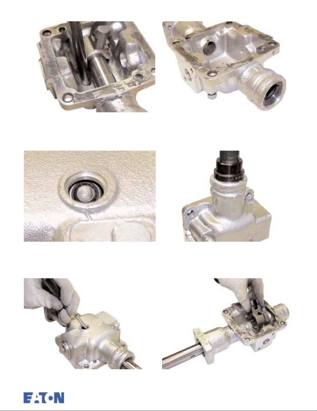
Remote Control Reassembly
7. Invert the housing and carefully drift out the
expansion plug.
8. Invert the housing, align the grooved pin in the
lever with the expansion plug hole.
1. If necessary renew the bearing bushes in the
housing using the special tool. The new bushes
are prefinished to the correct size.
2. If necessary renew the oil seal.
9. Drift out the pin. Remove the shaft and inner
lever.
3. Install the inner lever, long plain groove toward
the front of the housing.
5/013/4
 Loading...