

C24HD & C24HDS Broadcast Spreader
Assembly and Operating Instructions
PLEASE CONTACT US: IF YOU ARE MISSING ANY PARTS, HAVE ANY DIFFICULTY IN ASSEMBLY, OR HAVE ANY
QUESTIONS REGARDING THE SAFE OPERATION OF THIS SPREADER. THIS MODEL INCLUDES LIFETIME TECHNICAL
SU PP ORT. SUPPORT HOT LINE: 574-848-7491 or 800-294-0671, email: techsupport@earthway.com
HELPFUL HINTS:
; If your spreader does not spread evenly, be sure the FRONT on the gear box points to the front of the spreader. The impeller must
turn clockwise. Reversing the gearbox will cause the impeller to turn counter clockwise. Clean the impeller after each use as some
fertilizer may become stuck on the impeller blades and will cause uneven spreading.
; Your spreader is designed to be pushed at three miles per hour, which is a brisk walking speed. Slower or faster speeds will change
the spread patterns. Wet fertilizer will also change the spread pattern and ow rate.
; Clean and dry your spreader thoroughly after each use, wash between the shut-off plate and bottom of the hopper regularly. To
prevent rust, coat all metal parts (inside and out) including the frame tubes with a light oil or silicon spray.
; Gears are permanently lubricated at the factory. Do not open the gearbox or dirt may enter.
; If you use Rock Salt remove the agitator to prevent damage to the gearbox and remove salt from the hopper daily. Rock Salt will
reconstitute back into a solid block if left in the hopper overnight and will damage your gearbox if pushed with the block in place.
IF YOUR SPREADER COMES SEMI ASSEMBLED, SKIP TO STEP #7
Upper Handle
Cross
Brace
Lower
Handles
Pivot
Rod
Control
Rod
Handle
Impeller
Frame
Shaft
Frame
Brace
Gearbox
Gauge & Lever
Pivot
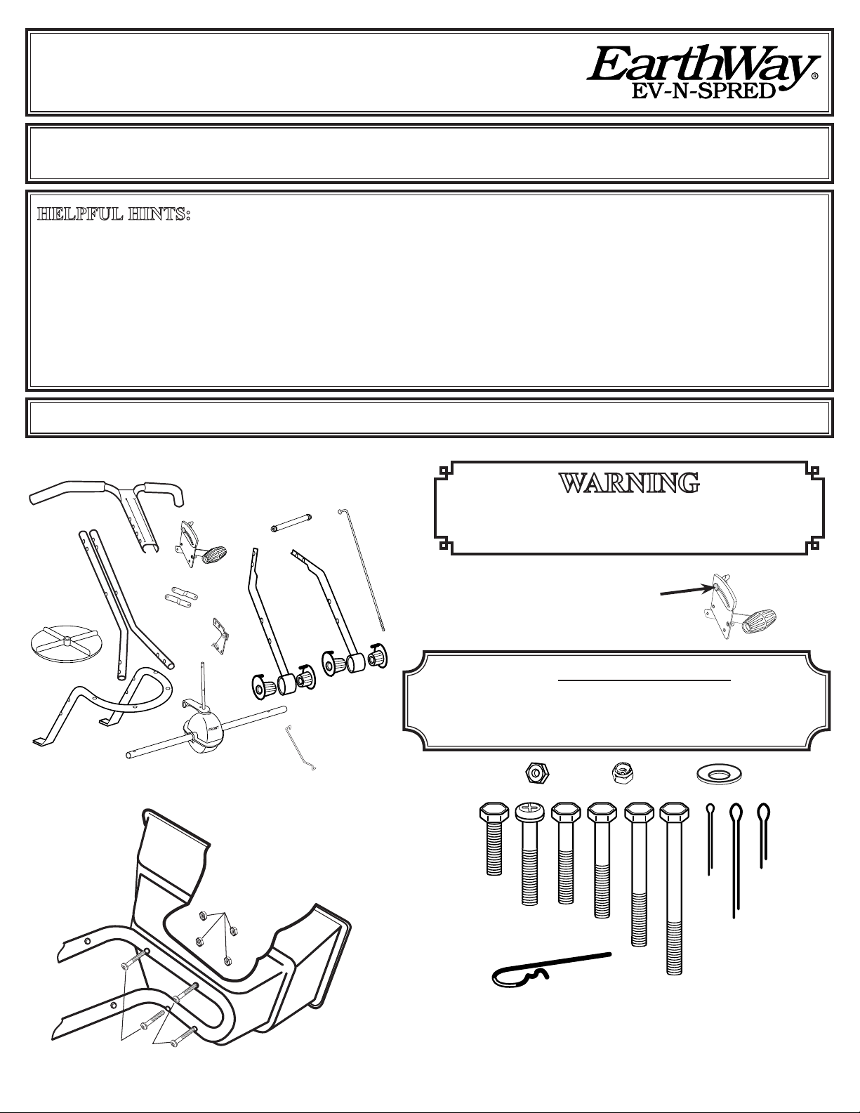
1. Remove and identify all of the loose parts from carton.
WA R N I NG
DO NOT USE AIR TOOLS TO ASSEMBLE. TO PREVENT
SEIZING SPRAY ALL NUTS & BOLTS WITH FURNITURE
POLISH OR WAX
Gauge Overlay is snapped over
the metal gauge. Replace the stop
vvvvvvvv
vvvvvvvv
bolt assembly to secure overlay on
the gauge.
ROCK SALT AND POWDERED MATERIALS SHOULD
NOT BE USED IN THIS SPREADER AS IT WILL DAMAGE
GEARBOX AND CAN VOID WARRANTY.
USE ONLY GRANULAR MATERIALS.
36305
Qty 2
36300
Qty 17
36404
Qty 18
(Qty 4 #36214)
1/4-20 X 1½”
Phillips Panhead
(Qty 4 #36300)
1/4-20 SS Locknut
36207
Qty 2
36105
Qty 1
36104
Qty 1
36103
Qty 1
36210
Qty 2
36214
Qty 4
36200
Qty 4
33117
Qty 1
36209
Qty 4
36205
Qty 3
2. Position hopper on side. Install frame using (4) 1/4-20 x 1 ½” Pan Head Phillips
machine screws and (4) 1/4-20 nylon insert locknuts. First put bolts through holes
in frame then through holes in bottom of hopper. Secure with locknuts. TIGHTEN
THESE LOCKNUTS NOW.
1-2012 Pt# 52142 PAGE 1
Impeller
EarthWay
EV-N-SPRED
®
Pinion
Shaft
1/8 x 1-1/4”
Cotter Pin (#36105)
Cross Brace
DRIVE WHEEL
HOLE
Gearbox Brace
T
N
O
R
F
COAST WHEEL
HOLE
Gearbox & Axle Assembly
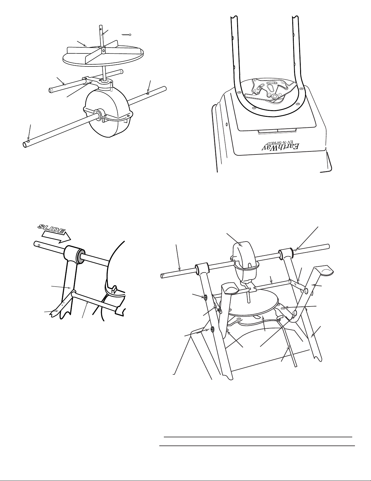
3. Install impeller onto pinion shaft. Insert 1/8” x 1¼” cotter pin
through impeller then through pinion shaft. Use hole nearest gear box.
Spread cotter pin to prevent from falling out. Next, install the Cross
Brace through the Gearbox Brace Support as shown above.
S
L
I
D
E
Coast wheel side
EV-N-SPRED
EarthWay
®
4. Install Gearbox by inserting the pinion shaft into hole in center
of hoppers bottom. The word “FRONT” on the gearbox must point
to FRONT of the hopper.
Drive wheel side
Gearbox & Axle Assembly
Gearbox
Axle Assembly
Lower Handle
Frame Brace
Cross Brace
5. Install Lower Handles onto Axle to both sides as
shown above.
6. A. Now insert 2 ¼” bolt with a cupped washer through
second hole in lower handle and through rst hole in
frame, secure with cupped washer and locknut.
B. Now insert 1 ½” bolt with a cupped washer through
rst hole in lower handle, then through frame brace, and
nally into the threaded connector in the Cross Brace.
[NOTE: Dimples on frame braces must be facing toward
gearbox as shown.] DO NOT TIGHTEN YET.
C. Next insert 1 ½” bolt through other end of frame
brace and through second hole in frame install cupped
washer and locknut.
DO NOT TIGHTEN YET.
Dimples
Cross Brace
1/4-20 x 1-1/2”
Hex Head Bolt
and cupped washer
Step 6B
Step 6C
Frame brace
1/4-20 x 2-1/4”
Hex Head Bolt
and
cupped washer
Step 6A
Impeller
Shut-Off
1/4-20 Locknut
and cupped washer
Pivot Rod
Frame
1/4-20 x 1-1/2”
Pan Head Bolt
Lower Handle
Notice cupped washer locatioNs
TIP: PosITIon cuPPed washers beTween nuT or bolT head and cha ssIs
NOW GO BACK AND TIGHTEN ALL NUTS AND BOLTS
STARTING WITH FIRST STEP. DO NOT OVER TIGHTEN.
PAGE 2

2” Cotter Pin
1” Cotter Pin
8. NOTE: BEFORE INSTALLING THE GAUGE &
LEVER ASSEMBLY AND UPPER HANDLE TO THE
HANDLE SHAFT, SELECT THE BEST POSITION
FOR THE OPERATOR’S COMFORT. You can
select lower, middle, or upper positions for best t to the
3 Position Handle
operator’s height. Insert 2 ¾” bolt through the Gauge, then
upper handle and nally through handle shaft. See example to
the right.
DO NOT TIGHTEN LOCKNUT YET.
9. Insert pivot rod into shut off plate as shown below. [TIP: Insert rod
end from the top, then push down & turn to lock in place.]
10. Insert other end of pivot rod into pivot and bracket assembly as
shown. [TIP: Insert rod end from the side that has the angle attached
to the bracket, then turn to lock in place as shown at the right and
above. The correct positioning of the Pivot Bracket has the Angle and
Attaching Arm facing away from the gearbox.]
7. Install drive wheel to axle using pin hole nearest to lower
handles as shown. Insert 2” cotter pin through wheel and
through axle. Bend with pliers to prevent pin from falling
out.
NEXT
Install coast wheel to axle, and then using outside pin
hole on the axle (as shown on the left), insert 1” cotter pin
through axle [NOTE: not thru the wheel]. Bend with pliers
to prevent pin from falling out.
TURN SPREADER UPRIGHT ON TO WHEELS
If you have any questions
please call 574-848-7491
Lower Position
Middle Position
Upper Position
¼-20
Lock Nut
and
cupped washer
Hex Head Bolt
¼-20 x 2¼”
Hex Head Bolt
and cupped washer
¼-20 x 2¾”
Angle
Attaching
Arm
Insert Pivot Rod
into Shut-Off
and rotate to secure
Notice cupped washer locatioNs
PAGE 3

11. Install handle shaft to lower handles and pivot & bracket assembly as shown. Using
(4) 1 ¾” bolts with cupped washers and (4) locknuts (2) cupped washers. [TIP: Attach
right side rst with cupped washers on both nuts and bolts, then attach left (Pivot
Setting #30
Bracket) side with washers only on the bolt side]
TIGHTEN BOLTS AND NUTS NOW.
12. Install attened end of control rod in to lever on gauge into
Control Rod Tabbed hole as shown. Turn to lock in place.
NEXT: Install (1) 1/4-20 Hex Nut [not a locknut] on to Control
Rod and thread halfway as shown below.
1/4-20 X 1-3/4”
Hex Head Bolt
with cupped washer
0
3
5
1
0
1
5
Gauge & Lever
0
3
5
1
0
1
5
Control Rod
Tabbed Hole
1/4-20
Lock Nut
and cupped
washer
Notice the position
of the double bend point.
Notice cupped washer locatioNs
Insert Control Rod
into
Pivot Bracket
CALIBRATION POINT
Attach 1/4-20 Regular
Hex Nuts
at these points.
13. Next push lever forward to setting “0”. Align control
rod with hole in pivot bracket, pull lever backward to insert
control rod through hole in pivot bracket. [TIP: If the lever
does not move easily, loosen slightly to make this step easier]
Now install 1/4-20 regular nut on to Control rod.
14. Pull lever back to setting “30” as shown. Next push
pivot & bracket forward so that the shut off plate in the
hopper is in the full open position. [NOTE: THE SETTING
OF “30” ON THE GAUGE & LEVER ASSEMBLY MUST
OPEN THE SHUT-OFF COMPLETELY FOR PROPER
CALIBRATION.] Now tighten the nuts against the pivot
bracket to prevent change in calibration. Test by opening and
closing the Gauge & Lever a few times to ensure an accurate
calibration.
Lever Tensioning Nut
Control Rod
DO NOT TIGHTEN NUTS YET.
1/4-20 x 1”
Hex Head Bolt
Stainless
1/4-20 Lock Nut
Stainless
16. Install the two 1/4-20 x 1” Stainless Steel bolts into holes located on each
side of the hopper and secure with 1/4-20 lock-nut. Next slide Debris Screen
under the two bolts inside the hopper.
PAGE 4
15. Tension on the ow control lever may be adjusted by
tightening or loosening the tension nut as shown above.
17. Insert Agitator to pinion shaft on inside of hopper.
NOTE: Position of at side of agitator. This pin
should be installed as shown above.

18. For normal operation both doors should be fully opened. To reduce ow to the left side, partially or completely close the door over the
S
p
r
e
a
d
P
a
t
t
e
r
n
rear (LARGE) hole. To reduce ow to the right side, partially or completely close the door over the front (SMALL) hole. Close both doors
for a narrow center spread pattern.
WARNING: If the optional side deector is being used in the down position, the plate over the rear (LARGE) hole MUST BE CLOSED
or an over application of material will occur.
SPREAD PATH
FULL Rate (one pass)
HALF Rate (two passes)
Each adjustable port
has 8 positions
Both ports open
Both ports closed
One port closed
The settings furnished on the Setting Matrix are intended as a guide only. Variations in physical characteristics of material applied, walking
speed, and roughness of ground surface may require slightly different spreader settings. Due to these conditions, Earthway Products, Inc.
makes no warranty as to the uniformity of coverage actually obtained from the settings listed.
5-YEAR LIMITED WARRANTY
Earthway Products, Inc. warrants this product free of defects in original workmanship and materials for a period of 5-Years to the end user
with the original purchase receipt. If a manufacturing non-conformance is found, Earthway Products, Inc. at its discretion will repair or
replace the part(s) or product at no charge provided the failure is not the result of incorrect installation, mishandling, misuse, tampering, or
normal wear and tear as determined by Earthway. Earthway at its discretion may require that the part(s) or product be returned along with
the original purchase receipt at owners’ expense for examination and compliance with the terms of this warranty. Do not return any product
without rst receiving authorization from Earthway Products, Inc. To seek remedy under this warranty, contact Earthway Products, Inc. at
574-848-7491, techsupport@earthway.com or write to Earthway Products, Inc. P.O. Box 547 Bristol, Indiana 46507 and describe the nature
of the manufacturing defect. SPECIFIC LIMITATIONS: This warranty covers only the part(s) or product; any labor charges associ-
ated with repair or replacement of non-conformances are specically excluded. Due to the corrosive nature of most fertilizers and ice melt
products, Earthway Products, Inc. makes no warranty against and specically excludes part(s) or product degradation or failure due to cor-
rosion or its effects. Clean and dry your spreader thoroughly after each use, as a preventative measure, coat all metal parts with a light oil or
silicon spray.
OPERATING INSTRUCTIONS
Before lling hopper, become familiar with the operation of this spreader.
5 Obtain proper setting for material to be used from the enclosed SETTING MATRIX included with this spreader, or from our web site
under the MANUALS SECTION.
5 Move stop bolt on rate gauge assembly to the proper setting.
5 While pushing spreader forward, pull control lever back to stop bolt.
5 To stop, push lever forward to close ow holes before you stop moving.
5 When nished, empty any remaining material from hopper.
5 Thoroughly wash spreader and allow to dry before storing. Apply coating of light oil to help prevent corrosion.
5 If you use Rock Salt, remove agitator when using Rock Salt to prevent damage to the gearbox.
Earthway Products, Inc.
1009 Maple Street, PO Box 547
Bristol, IN 46507
Be sure to give the following information when ordering.
For Your Records
Date Purchased
Call (574) 848-7491, 800-294-0671, or email: parts@earthway.com
Place of Purchase
HOW TO ORDER SPARE PARTS
All spare parts listed may be ordered direct from
EarthWay Products, Inc.
Model Number
Part Number
Part Description
for current prices.
PAGE 5

21
1
30
29
38
39
37
28
5
27
5
3
5
5
7
6
77002
OPTIONAL
Heavy-Duty
Rain Cover
Earthway Products, Inc.
P.O. Box 547
Bristol, Indiana 46507
(574) 848-7491
35
36
22
11
23
5
35
35
26
22
35
vvvvvvvv
24
5
6
31
25
vvvvvvvv
32
10
35
8
33
34
5
24
11
9
12
14
4
35
16
15
13
35
2
60060R
OPTIONAL
Heavy-Duty
Rain Cover
&
36
Side Deflector Kit
9
11
22
11
12
18
19
20
60166R
OPTIONAL
3-Side Deflector Kit
17
a
y
W
18
h
S
t
e
r
t
a
E
t
i
n
g
s
0
2
0
1
3
0
0
o
c
S
s
e
e
t
L
t
i
n
g
s
0
3
2
0
1
0
0
Standard Settings (12196) Gauge Overlay and
OPTIONAL Lesco Settings (12195) Gauge Overlay
C24HD & C24HDS professioNal Broadcast spreader
Key # Part # Description Key # Part # Description
1 40003 SQUARE SCREEN
2 60219 HOPPER ASSEMBLY 22 36205 1/4-20 X 2 1/4" HHCS S.S.
3 33117 AGITATOR 23 24301 HANDLE SHAFTS WELDED (C24HDS)
4 36214 1/4-20 X 1 1/2" PHPMS S.S. 23 25301 HANDLE SHAFT (C24HD)
5 36300 1/4-20 NYLON INSERT LOCKNUT S.S. 24 36305 1/4-20 HEX NUT STAINLESS STEEL
6 36210 1/4-20 X 1" HHMS S.S. 25 44251 PIVOT ROD
7 12209 HOPPER BUSHING (C24/C25) 26 42256 CONTROL ROD
8 12278 SHUT OFF PLATE ASSEMBLY - COMMERCIAL 27 60298 GAUGE & LEVER ASSEMBLY
9 24202 LOWER HANDLE (C24HDS) COMPLETE 28 36207 1/4-20 X 2 3/4" HHCS S.S.
9 25202 LOWER HANDLE COMPLETE (C24HD) 29 12273 GRIP 9.75" LONG
10 60299 PIVOT & BRACKET ASSEMBLY 30 60069 UPPER HANDLE ASSEMBLY W/GRIPS C-SERIES PAINTED
11 36200 1/4-20 X 1 1/2" HHCS S.S. 30 60070 UPPER HANDLE ASSEMBLY W/GRIPS C-SERIES STAINLESS
12 42237 FRAME BRACE 31 36208 #6 X 3/8" TYPE 25 PHPS S.S.
13 24704 CROSS BRACE (11.125") 32 11927 SHUTOFF SUPPORT- LARGE
14 24100 FRAME (C24HDS) 33 11926 SHUTOFF SUPPORT- SMALL
14 25102 FRAME PAINTED (C24HD) 34 31138 #8 X 3/8" PMT #8 HD COARSE BLACK
15 12109 IMPELLER (9" DIA) 35 36404 1/4 CUPPED WASHER S.S.
16 36105 1/8" X 1 1/4" COTTER PIN S.S. 36 36209 1/4-20 X 1 3/4" HHCS S.S.
17 60334 GEAR BOX & AXLE ASSEMBLY 37 60027 WING NUT ASSEMBLY BLACK
18 12352 BEARING (COMMERCIAL) 38 37100 1/4-20 X 1" CARRIAGE BOLT ZINC
19 36103 3/16 X 2" COTTER PIN S.S 39 12147 SPACER (PIVOT LINK)
20 19117 13" DIA PNEU TIRE DRIVE
21 36104 3/16 X 1" COTTER PIN S.S.
 Loading...