

EarthWay 2100P Estate Assembly And Operating Instructions Manual
2100P EstatE
Broadcast sPrEadEr
ASSEMBLY and OPERATING INSTRUCTIONS
PLEASE CALL IF YOU ARE MISSING ANY PARTS, HAVE ANY DIFFICULTY IN ASSEMBLY, OR HAVE ANY QUESTIONS
REGARDING THE SAFE OPERATION OF THIS SPREADER. THIS MODEL INCLUDES LIFETIME TECHNICAL SUPPORT
SUPPORT HOT LINE: 574-848-7491 or 800-294-0671, Email: tEchsuPPort@Earthway.com
HELPFUL HINTS: READ THE DIRECTIONS BEFORE ASSEMBLY
; If your spreader does not spread evenly, be sure the FRONT on the gear box points to the front of the spreader. The
impeller must turn clockwise. Reversing the gearbox will cause the impeller to turn counter clockwise. Clean the impeller
plate after each use. Fertilizer stuck on the impeller blades will cause uneven spreading.
; Your spreader is designed to be pushed at three miles per hour, which is a brisk walking speed. Slower or faster speeds
will change the spread patterns. Wet fertilizer will also change the spread pattern and ow rate. Clean and dry your
spreader thoroughly after each use. Coat all metal surfaces (inside & outside of chassis tubes) with light oil or silicon spray
to help prevent corrosion. Wash between the shut off plate and bottom of the hopper. Do not use powdered materials.
; Gears are permanently lubricated at the factory. Do not open the gearbox or dirt may enter.
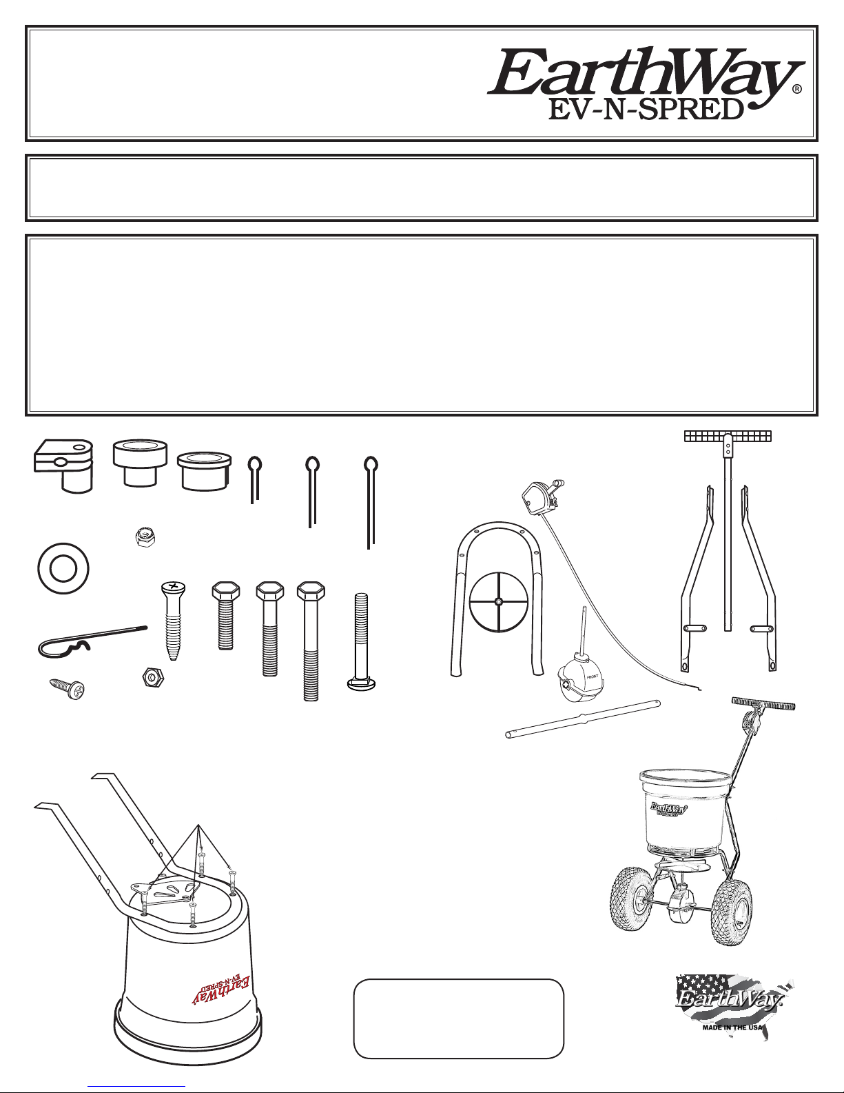
Lower
Housing Clip
Axle
Washer
#10 x ⅝”
Screw
Bushing
¼-20
Lock Nut
Agitator
Axle
Hex Nut
Bearing
#12 x 1¼”
Flat Head Screw
¼-20
Axle
Cotter Pin
¼-20 x
1¼” Bolt
⅛ x ¾”
1½” Bolt
¼-20 x
⅛ x 1¼”
Cotter Pin
¼-20 x
2” Bolt
1. Remove and identify all loose parts from carton.
(Qty 4) #31105
#12 X 1¼”
Flat Head Screw
2. Position the Hopper on its top as shown
to the left. Install frame using (4) #12 x
1¼” Flat Head Phillips screws. TIGHTEN
THESE NOW - use care to not over tighten
⅛ x 1¾”
Cotter Pin
¼-20 x 1¾”
Carriage Bolt
FRAME
IMPELLER
CONTROL
ASSEMBLY
AXLE
UPPER HANDLE
ASSEMBLY
DRAW BAR
&
BRACE ASSEMBLY
GEARBOX
Warning
Remove agitator when
using Rock Salt to prevent
gearbox damage
MADE IN THE USA
9-2014 Pt.# 52159 PAGE 1
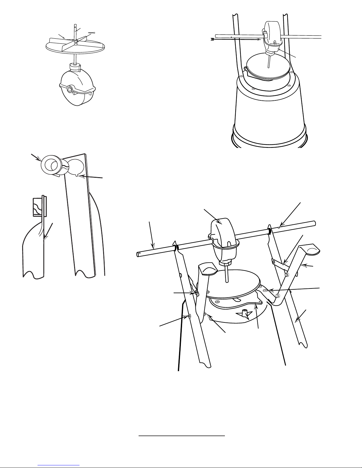
Pinion
Shaft
Impeller
T
N
O
R
F
⅛ x 1¼”
Cotter Pin
Gearbox Assembly
3. Install impeller onto pinion shaft. Insert ⅛”x 1¼” Cotter pin
through impeller then through pinion shaft. Use hole closest to the
gear box. Spread cotter pin to prevent from falling out.
Axle Bearing
4. Install gear box by inserting the pinion shaft into hole in center of hoppers
bottom. The word “FRONT” on the gearbox must point to Front of the
Notch
hopper. Follow label instructions on hopper. Next, slide axle thru the gearbox
with the drive wheel hole positioned as shown in the drawings below.
SLIDE
NT
O
R
F
Gearbox
FRONT
Flat
Side
5. Install axle bearings to both Draw bars.
NOTE: Notch on bearings and in the Draw
bar line up. Bearings must go through at
side of lower handle.
COAST WHEEL SIDE
¼-20 x 1¼”
Hex Head Bolt
¼-20 x 2”
Hex Head Bolt
Gearbox Assembly
Impeller
¼-20 Locknut
DRIVE WHEEL SIDE
Frame brace
Frame
Flat Head
Screw
Draw Bar
Shut-Off
NOW GO BACK AND TIGHTEN ALL NUTS AND BOLTS STARTING WITH FIRST
STEP. DO NOT OVER TIGHTEN.
PAGE 2
6. Install lower handles onto axle to both sides as shown. Insert ¼-20 x 2” bolt through hole
in Draw Bar and through rst hole in frame install locknut. DO NOT TIGHTEN. Next insert
¼-20 x 1¼” bolt through frame brace and through second hole in frame install locknut.
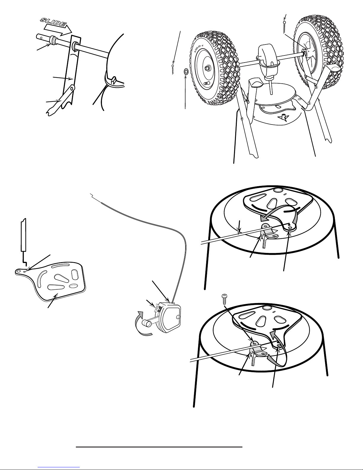
1¾” Cotter Pin
S
L
I
D
E
¾” Cotter Pin
Bushing
Gearbox
&
Axle
Drawbar
Frame Brace
Flat Washer
7. Slide axle bushing over axle and into axle bearing to both sides as shown.
8. Install drive wheel to axle using pin hole nearest to lower handles as shown. Insert 1¾”
Cotter pin through wheel and through axle. Bend with pliers to prevent pin from falling
out.
9. Install coast wheel to axle using outside pin hole. As shown, add the at washer, and
insert ¾” Cotter pin through axle (NOT THRU THE WHEEL). Bend with pliers to
prevent pin from falling out.
Control Wire
Control
Wire
Small hole
for Control wire
Control
Assembly
#30
Shut-Off
Plate
Rate Handle
10. Install Control Assembly by inserting the bent wire end into the
small hole in the shut-off plate from the bottom of the spreader as shown
above. TIP: The wire will t into the hole to the rst bend, then you need
to lay the Control Wire into the Lower Housing Clip. Close the Lower
Housing Clip with a snap and secure with #10 x ⅝” screw and snug to a
loose t - do not tightEn.
Lower Housing Clip
#10 x 5/8”
Screw
Lower Housing Clip
Larger Hole
Larger Hole
TURN SPREADER UPRIGHT ON TO WHEELS.
PAGE 3
 Loading...