

Page 1
Operator’s Manual
GAS/OIL
RATIO
50:1
Original Operating Instructions
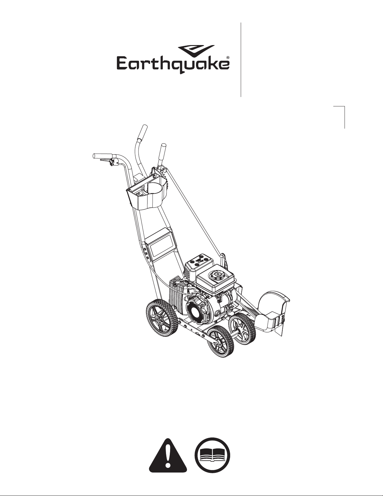
Edger
SN
Get parts online at
www.getearthquake.com
Includes models:
23275
24000
P/N: 22945
ECN: 11775
REV3: 8/24/17
© 2017-2018 Ardisam, Inc.
All Rights Reserved
Page 2
Operator’s Manual
Edger
INTRODUCTION
Congratulations on your investment in quality. Thank you for purchasing an edger from Earthquake®. We have worked to ensure that
your product meets the highest standards for usability and durability. With proper care, your edger will provide many years of service.
Please read this entire manual before installation and use. Earthquake reserves the right to change, alter or improve the
product and this document at any time without prior notice.
CONTENTS
Introduction/Registration and Service ................................................................................................................................................................................. 2
Warnings ..........................................................................................................................................................................................................................................3
General Safety Rules ....................................................................................................................................................................................................................4
Safety Precautions........................................................................................................................................................................................................................5
Service Safety/Symbols .............................................................................................................................................................................................................. 6
Safety Decals .................................................................................................................................................................................................................................. 7
Features and Controls ................................................................................................................................................................................................................. 8
Specications .................................................................................................................................................................................................................................9
Assembly................................................................................................................................................................................................................................. 10-11
General Operation .............................................................................................................................................................................................................. 12-13
Edging Tips ...................................................................................................................................................................................................................................14
Slope Guide................................................................................................................................................................................................................................. .14
Maintenance ................................................................................................................................................................................................................................15
Transporting and Storage .......................................................................................................................................................................................................16
Troubleshooting .........................................................................................................................................................................................................................16
Troubleshooting Guide ............................................................................................................................................................................................................17
Illustrated Parts Breakdown.............................................................................................................................................................................................18-22
Warranty ........................................................................................................................................................................................................................................23
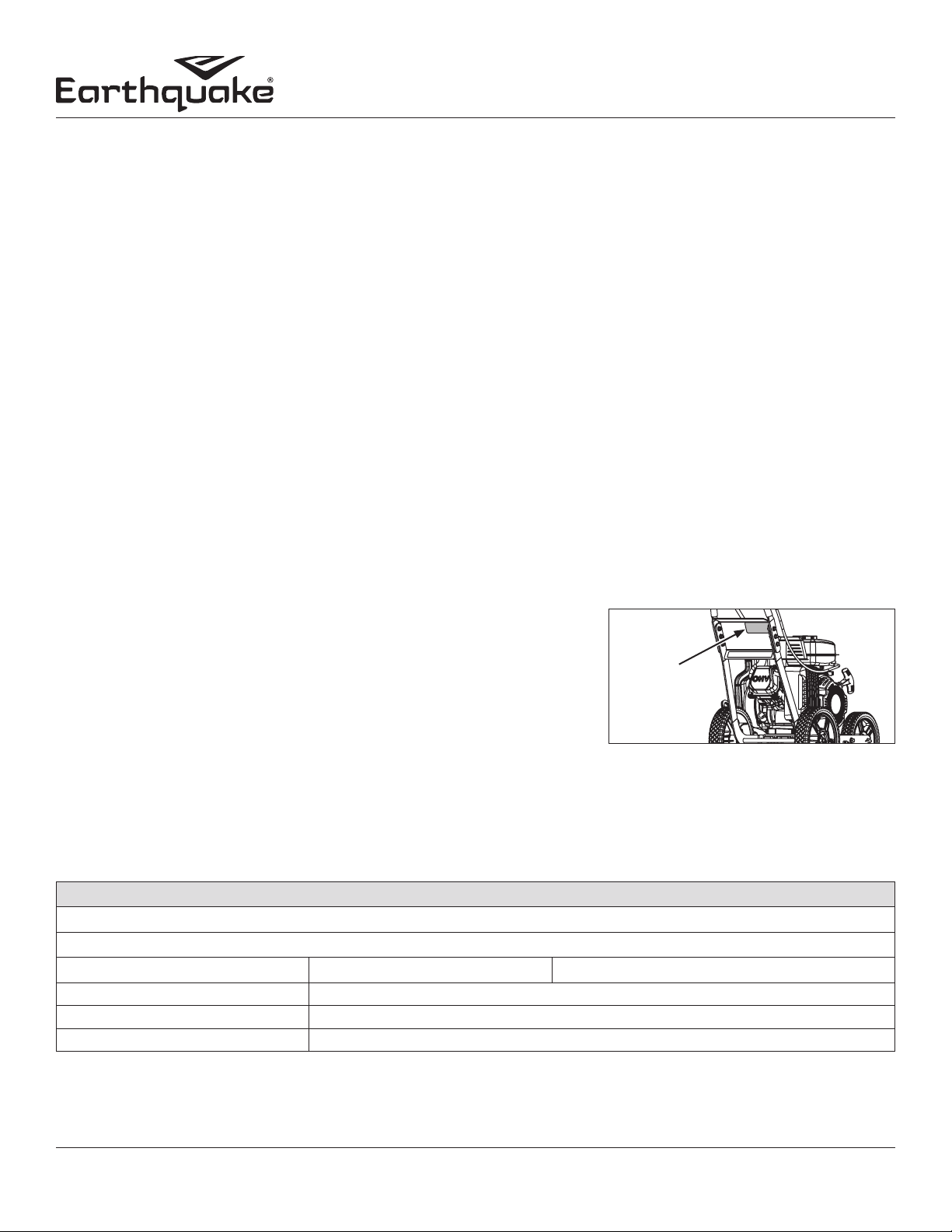
When contacting your authorized dealer or Earthquake for replacement
parts, service, or information you MUST have these numbers. Do not take
this product back to the store from which it was purchased
Record your model name/number, manufacturer’s identication numbers, and
engine serial numbers in the space provided for easy access.
NOTE: For location of engine identication numbers, refer to the engine owner’s
manual.
Serial
Number
Decal
REGISTRATION AND SERVICE
Record the product number and serial number in the space provided for easy reference when ordering parts or requesting technical support. Excluding emissions-related warranty items, the warranty is valid only if the completed registration is received by
Earthquake within 30 days of purchase. SEE WARRANTY SECTION FOR MORE INFORMATION. You can register your war-
ranty online by visiting www.getearthquake.com, or by mailing it to: Warranty Department, 1160 Eighth Avenue, Cumberland, WI
54829. If you do not have access to www.getearthquake.com, call our customer service department at (800) 345-6007 Mondays
through Fridays from 8 a.m. to 5 p.m. CST.
OWNERSHIP RECORDS
Owner’s Name:
Owner’s Address:
City:
Model Number: Serial Number:
Engine Model: Engine Serial Number:
Date of Purchase: Notes:
State/Province: Zip Code/Postal Code:
This manual may contain information for several models. Read and keep this manual for future reference. This manual contains important
information on SAFETY, ASSEMBLY, OPERATION, AND MAINTENANCE. The owner must be certain that all the product information is included with
the unit. This information includes the MANUAL, the REPLACEMENT PARTS and the WARRANTIES. This information must be included to make sure
state laws and other laws are followed. This manual should remain with the unit even if it is resold.
2 Check for parts online at www.getearthquake.com or call 800-345-6007 M-F 8-5
Page 3
WARNINGS AND SAFETY PRECAUTIONS
Owner’s Responsibility
Accurate assembly, and safe and eective use of the edger is
the owner’s responsibility.
• Read and follow all safety instructions.
• Carefully follow all assembly instructions.
• Maintain the edger according to directions and
schedule included in this operator’s manual.
• Ensure that anyone who uses the edger is familiar
with all controls and safety precautions.
Special Messages
Your manual contains special messages to bring attention to
potential safety concerns, machine damage as well as helpful
operating and servicing information. Please read all the information carefully to avoid injury and machine damage.
NOTE: General information is given throughout the
manual that may help the operator in the
operation or service of the machine.
Important Safety Precautions
Please read this section carefully. Operate the edger according to the safety instructions and recommendations outlined
here and inserted throughout the text. Anyone who uses this
edger must read the instructions and be familiar with the controls. Learn how to control the edger at all times.
This symbol points out important safety
instructions which if not followed could endanger your personal safety. Read and follow all
instructions in this manual before attempting
to operate this equipment.
Operator’s Manual
Edger
WARNING
WARNING INDICATES A HAZARD WHICH, IF NOT
AVOIDED, COULD RESULT IN DEATH OR SERIOUS IN
JURY AND/OR PROPERTY DAMAGE.
CAUTION
CAUTION INDICATES YOU CAN BE HURT OR YOUR
EQUIPMENT DAMAGED IF THE SAFETY INSTRUC
TIONS THAT FOLLOW THIS SIGNAL WORD ARE NOT
OBEYED.
IMPORTANT
INDICATES HELPFUL INFORMATION FOR PROPER AS
SEMBLY, OPERATION, OR MAINTENANCE OF YOUR
EQUIPMENT.
WARNING
CALIFORNIA PROPOSITION 65 WARNING
ENGINE EXHAUST FROM THIS PRODUCT CONTAINS
CHEMICALS KNOWN TO THE STATE OF CALIFORNIA
TO CAUSE CANCER, BIRTH DEFECTS, OR OTHER RE
PRODUCTIVE HARM.
WARNING
YOU MUST READ, UNDERSTAND AND COMPLY WITH
ALL SAFETY AND OPERATING INSTRUCTIONS IN
THIS MANUAL BEFORE ATTEMPTING TO SETUP AND
OPERATE YOUR MACHINE.
FAILURE TO COMPLY WITH ALL SAFETY AND
OPERATING INSTRUCTIONS CAN RESULT IN LOSS OF
MACHINE CONTROL, SERIOUS PERSONAL INJURY TO
YOU AND/OR BYSTANDERS, AND RISK OF EQUIPMENT
AND PROPERTY DAMAGE. THE TRIANGLE IN THE TEXT
SIGNIFIES IMPORTANT CAUTIONS OR WARNINGS
WHICH MUST BE FOLLOWED.
Intended Use /
Foreseeable Misuse
This is a motorized, walk-behind edger used for maintaining
and trimming unwanted weeds and grass from areas next to
concrete or other landscaping items. This edger is not to be
used to cut wood or concrete. It is pedestrian controlled. It has
a petrol-fuelled internal combustion engine that powers the
cutting wheel. It shall not be used for any other purpose.
3Check for parts online at www.getearthquake.com or call 800-345-6007 M-F 8-5
Page 4

Operator’s Manual
Edger
GENERAL SAFETY RULES
• Read, understand, and follow all instructions on the machine
and in the manual(s). Be thoroughly familiar with the controls
and the proper use of the machine before starting.
• Use this equipment for its intended purpose only.
• Familiarize yourself with all of the safety and operating
decals on this equipment and on any of its attachments or
accessories.
• Do not put hands or feet near or under rotating parts.
• Only allow responsible individuals who are familiar with the
instructions to operate the machine. Do not allow children
to operate this machine. Keep small children away from the
area while in use. Do not allow adults to operate the machine
without proper instruction.
• Thoroughly inspect the area where the machine is to be
used and remove all foreign objects. Your equipment can
propel small objects at high speed causing personal injury or
property damage. Stay away from breakable objects, such as
house windows, automobiles, greenhouses, etc.
• Wear appropriate clothing such as a long-sleeved shirt or
jacket. Also wear long trousers or slacks. Do not wear shorts.
Never wear sandals, sneakers, or open shoes, and never
operate the machine with bare feet.
• Do not wear loose clothing or jewelry. They can get caught in
moving parts. Always keep hands, feet, hair and loose clothing
away from any moving parts on engine and machine.
• Always wear safety goggles or safety glasses with side shields
when operating the machine to protect your eyes from
foreign objects which can be thrown from the unit. Always
wear a protective hearing device.
• Always wear work gloves and machine safety shoes during
operation. Wear footwear that will improve footing on
slippery surfaces. Leather work shoes or short boots work well
for most people. These will protect the operator’s ankles and
shins from small sticks, splinters, and other debris.
• It is advisable to wear protective headgear to prevent the
possibility of being struck by small ying particles, or being
struck by low hanging branches, twigs, or other objects which
may be unnoticed by the operator.
• Do not operate the machine without proper guards or other
safety protective devices in place.
• See manufacturer’s instructions for proper operation and
installation of accessories. Only use accessories approved by
the manufacturer.
• Operate only in daylight or good articial light.
• Do not operate product when fatigued or under the inuence
of alcohol, drugs or other medication which can cause
drowsiness or aect your ability to operate this machine safely.
• Never operate machine in wet grass. Always be sure of your
footing; keep a rm hold on the handle and walk; never run.
• Watch for trac whenever you are operating near, or when
crossing roads.
• If the equipment should start to vibrate abnormally, stop the
engine (motor), disconnect the spark plug wire and prevent it
from touching the spark plug. Check immediately for cause.
Vibration is generally a warning of trouble. If the noise or
vibrations of the machine increase, stop immediately and
perform an inspection.
• Never leave the machine unattended when the engine is
running.
• Regularly inspect the machine. Make sure parts are not bent,
damaged or loose.
• Temperature of muer and nearby areas may exceed 150°
F (65° C). Allow muffler and engine areas to cool before
touching. Never pick up or carry the machine while the engine
is running.
• Prolonged exposure to noise and vibration from gasoline enginepowered equipment should be avoided. Take intermittent breaks
and/or wear ear protection from engine noise as well as heavy
work gloves to reduce vibration in the hands.
• Keep all screws, nuts and bolts tight.
• Do not transport the machine from one place to another with
the engine running.
• When moving the packaged machine, always do so with a
partner.
• Check local regulations for age restrictions on use of this
machine.
• Stay away from rotating parts. Place protective covers over
rotating parts.
PRODUCTSPECIFIC SAFETY RULES
• Do not edge above underground utilities, including water
lines, gas lines, electric cables, or pipes. Do not operate the
machine on terrain/soil with large rocks and foreign objects
which can damage the equipment.
• After striking a foreign object, stop the engine. Remove the
wire from the spark plug. Inspect the machine for damage. If
damaged, repair before starting and operating the machine.
• The blade of the edger should not rotate when the engine
is idling. If it does rotate when engine is idling, contact
Earthquake® for instructions.
• If an object becomes lodged in the blade guard area, turn
engine o, remove the wire from the spark plug and secure,
allow to cool before attempting to remove the foreign object.
• Use edger only for edging along flower beds, terraces,
sidewalks and curbs. Trim along buildings trees, walks, marker
hedges and fences.
4 Check for parts online at www.getearthquake.com or call 800-345-6007 M-F 8-5
Page 5

ENGINE SAFETY PRECAUTIONS
Preventing Carbon Monoxide Poisoning
• Never try to ventilate engine exhaust indoors. Carbon
monoxide can reach dangerous levels very quickly.
• Never run engine outdoors where exhaust fumes may be
pulled into a building.
• Never run engine outdoors in a poorly ventilated area
where the exhaust fumes may be trapped and not easily
taken away. (Examples include: in a large hole or areas
where hills surround your working area.)
• Never run engine in an enclosed or partially enclosed area.
(Examples include: buildings that are enclosed on one or
more sides, under tents, car ports or basements.)
• Never point the exhaust muer towards anyone. People
should always be many feet away from the operation of the
engine and its attachments.
• Do not change the engine governor settings or over-speed
the engine.
• Always keep materials and debris clear of muer guard
and other hot engine parts.
• Always make sure the exhaust pipe is free of foreign objects.
Operator’s Manual
Edger
WARNING
ENGINES GIVE OFF CARBON MONOXIDE, AN ODORLESS,
COLORLESS, POISONOUS GAS. CARBON MONOXIDE MAY
BE PRESENT EVEN IF YOU DO NOT SMELL OR SEE ANY
ENGINE EXHAUST. BREATHING CARBON MONOXIDE CAN
CAUSE NAUSEA, FAINTING OR DEATH, IN ADDITION TO
DROWSINESS, DIZZINESS AND CONFUSION.
IF YOU EXPERIENCE ANY OF THESE SYMPTOMS, SEEK
FRESH AIR AND MEDICAL ATTENTION IMMEDIATELY.
START AND RUN ENGINE OUTDOORS. DO NOT START OR
RUN ENGINE IN ENCLOSED AREA, EVEN IF DOORS OR WIN
DOWS ARE OPEN.
HOT GASES ARE A NORMAL BYPRODUCT OF
COMBUSTION. FOLLOW ALL SAFETY INSTRUCTIONS TO
PREVENT BURNS AND FIRES.
DO NOT ALTER/MODIFY ENGINE:
NEVER ALTER OR MODIFY THE ENGINE FROM THE FAC
TORY. SERIOUS INJURY OR DEATH MAY OCCUR IF ENGINE IS
MODIFIED OR ALTERED.
WHEN WORKING ON OR REPLACING PARTS FOR THE
ENGINE OR PRODUCT, YOU MUST ALWAYS DISCONNECT
SPARK PLUG WIRE FROM THE SPARK PLUG AND KEEP IT
AWAY FROM THE SPARK PLUG.
Gasoline Fires and Handling Fuel Safely
• Use extra care in handling gasoline and other fuels. They
are ammable and vapors are explosive.
• When storing extra fuel be sure that it is in an appropriate
container and away from any re hazards. Prevent re
and explosion caused by static electric discharge. Use
only nonmetal, portable fuel containers approved by the
Underwriter’s Laboratory (U.L.) or the American Society for
Testing & Materials (ASTM).
• Always ll fuel tank outside in a well ventilated area. Never
ll your fuel tank with fuel indoors. (Examples include:
basement, garage, barn, shed, house, porch, etc.) Never
ll tank near appliances with pilot lights, heaters, or other
ignition sources. If the fuel has to be drained, this should be
done outdoors and with the proper equipment. The drained
fuel should be stored in a container specically designed for
fuel storage or it should be disposed of carefully.
• Never remove the fuel cap or add fuel with the engine
running. Stop engine and allow to cool before removing
the fuel cap/and or relling the engine.
• Do not smoke near or while handling engine fuel.
• Never drain fuel from engine in an enclosed area.
• During storage, tightly screw down fuel cap.
• Never pour fuel from engine fuel tank.
• Never siphon fuel by mouth to drain fuel tank.
• Always have an adult ll the fuel tank and never allow
children to ll the engine.
• Never allow an adult or anyone under the inuence of
drugs or alcohol to ll the engine.
• When storing gasoline or equipment with fuel in the tank,
store away from furnaces, stoves, water heaters or other
appliances that have a pilot light or other ignition source
because they can ignite gasoline vapors.
Prevention of Burns and Fires
• Never remove the muer guard from the engine.
• Never touch the muer guard because it is extremely hot
and will cause severe burns.
• Never touch parts of the engine that become hot after
operation.
• Always keep materials and debris away from muer guard
and other hot parts of the engine to avoid res.
Burns and Fires
• The muer, muer guard and other parts of the engine
become extremely hot during the operation of the engine.
These parts remain extremely hot after the engine has
stopped.
• Do not use engine around dry brush, cloth rags, or other
ammable materials.
• Never operate the engine without the muer guard in place.
• The engine exhaust becomes very hot during operation.
Keep engine at least three feet away from buildings and
other equipment during operation.
5Check for parts online at www.getearthquake.com or call 800-345-6007 M-F 8-5
Page 6

Operator’s Manual
Edger
SERVICE SAFETY
• Always stop the engine whenever you leave the
equipment, before cleaning, repairing or inspecting the
unit. Engine should be turned o and cool, spark plug wire
must be removed from spark plug before any repairs or
adjustments are attempted. Never make adjustments or
repairs with the engine (motor) running. Disconnect the
spark plug wire, and keep the wire away from the plug to
prevent accidental starting.
• Always wear eye protection when you make adjustments or
repairs.
• Keep all nuts and bolts tight and keep equipment in good
condition. Never tamper with safety devices. Check their
proper operation regularly.
• When servicing or repairing the engine, do not tip the
engine over or up unless specically instructed to do so in
this manual. Service and repair procedures can be done with
the engine in an upright position. Some procedures will be
easier if the engine is lifted on a raised platform or working
surface.
• To reduce re hazard, keep engine free of grass, leaves, or
other debris build-up. Clean up oil or fuel spillage. Allow
engine to cool before storing.
• Stop and inspect the equipment if you strike an object.
Repair, if necessary, before restarting.
• Clean and replace safety and instruction decals as
necessary.
• Inspect engine before storage. When not in use, disconnect
spark plug lead and store indoors in a dry place locked or
otherwise inaccessible to children.
• Use only original equipment parts from Earthquake®,
including all nuts and bolts.
CONTROL AND OPERATING SYMBOLS
Pictured below are control and operating symbols on the unit
or in this manual. Before you operate your unit, learn and
understand the purpose for each symbol.
SAFETY OR HAZARD SYMBOLS
A B
G
M
C
H
N
I J
O
D
P
A: Warning!
B: Read Owner’s Manual Before Operating Machine.
C: Only Operate When at a Safe Distance From Others.
D: Remove Objects that Could Be Thrown By This Machine.
E: Dangerous Moving Parts.
F: Be Aware of Moving Parts.
G: Wear Ear and Eye Protection At All Times.
H: Do Not Service or Adjust Moving Parts Unless Engine is
Stopped and Spark Plug Wire is Disconnected.
I: Dress Appropriately And Wear Sturdy Footwear.
J: Toxic Fumes —Do Not Operate in Unventilated Areas.
K: Hot Surfaces.
L: Fire Hazards.
M. Do Not Use In Thunderstorms--For severe weather, stop
operation of this machine and seek shelter.
N. Keep Hands at a Safe Distance from Blade.
O. Keep Feet at a Safe Distance from Blade.
P. Do Not Use Above Underground Utility Lines And Pipes.
Q. Shock Hazard.
R. Hot! Do Not Touch!
E
K L
Q
F
R
On/O Fuel Shuto
Choke
6 Check for parts online at www.getearthquake.com or call 800-345-6007 M-F 8-5
Page 7
CAUTION
Operator’s Manual
Edger
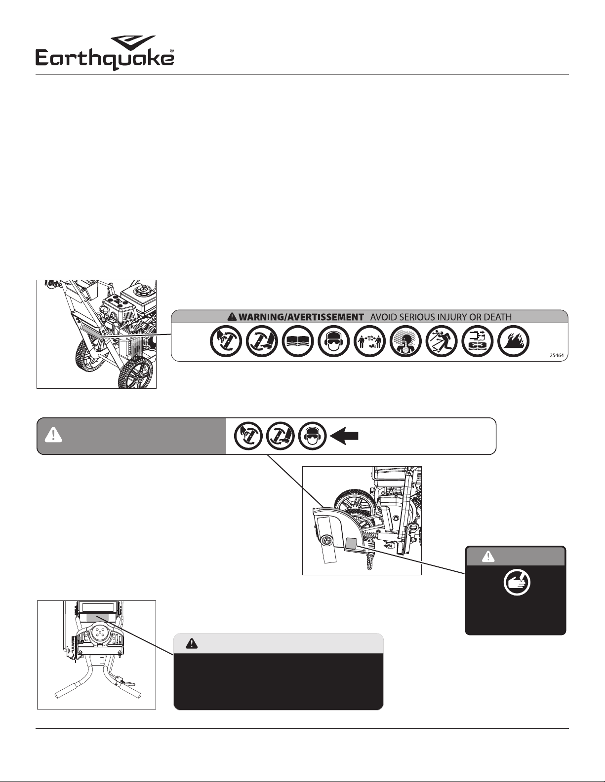
SAFETY DECALS
This unit has been designed and manufactured to provide you with the safety and reliability you would expect from an industry
leader in outdoor power equipment manufacturing.
Although reading this manual and the safety instructions it contains will provide you with the necessary basic knowledge to operate this equipment safely and eectively, we have placed several safety labels on the unit to remind you of this important information while you are operating your unit.
All DANGER, WARNING, CAUTION and instructional messages on your unit should be carefully read and obeyed. Personal bodily
injury can result when these instructions are not followed. The information is for your safety and it is important! The safety decals
below are on your unit.
If any of these decals are lost or damaged, replace them at once. See your local dealer or contact Earthquake® directly for replacements. These labels are easily applied and will act as a constant visual reminder to you, and others who may use the equipment,
to follow the safety instructions necessary for safe, eective operation.
25464
DECAL EDGER PICTORIAL SAFTY
DANGER/PELIGRO
DECAL EDGER BLADE SHIELD
26770
25631
DECAL CAUTION
Help Avoid Injury / Éviter les blessures
- When Leaving: Stop Engine / Avant de quitter: Arrêter le moteur
- Keep Shields and Safety Devices In Place /
Garder les écrans et mécanismes de sécurité en place
- Read Operator Manual / Lire le manuel de l’utilisateur
- Always Wear Safety Goggles or Safety Glasses /
Toujours porter des lunettes à coques ou des lunettes de sécurité
KEEP AWAY. ROTATING BLADE.
RESTEZ Á L’ÉCART. LAME EN ROTATION.
MANTÉNGASE ALEJADO.
CUCHILLA GIRATORIA.
DECAL DANGER KEEP
HANDS FEET AWAY
GARDER LES MAINS ET LES
25631
26770
24940
DANGER
KEEP HANDS AND
FEET AWAY.
PIEDS ÉLOIGNÉS.
24940
7Check for parts online at www.getearthquake.com or call 800-345-6007 M-F 8-5
Page 8
Operator’s Manual
Edger
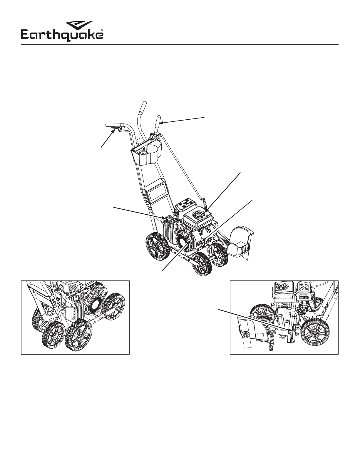
FEATURES & CONTROLS
Control Functions
The information below briey describes the function of individual controls. Operating requires the combined use of several controls applied in specic sequences. To learn what combination and sequence of controls to use for various tasks see the OPERATION section.
*For engine features and controls see engine manual.
BLADE DEPTH CONTROL LEVER
ENGINE THROTTLE
FUEL FILL
ON/OFF SWITCH
CHOKE
RECOIL
STARTER
ANGLE ADJUSTMENT
CURB WHEEL 24000 ONLY
Engine Throttle: Located on the right side handle, as engine throttle is depressed against the handle the engine speed will increase and start the edger blade. When engine throttle is released the engine will go back to idle and blade will stop turning.
Blade Depth Control Lever: The blade depth control lever is located on the left side of the upper handle. It is used to control the
depth of the cut. The further forward the blade depth control lever is moved, the deeper into the soil the edger blade will cut.
Recoil Starter: The recoil starter is used to start the engine.
Curb Wheel (Optional): The Curb Wheel Kit oers on the go height adjustment.
8 Check for parts online at www.getearthquake.com or call 800-345-6007 M-F 8-5
Page 9

Operator’s Manual
Edger
SPECIFICATIONS
ENGINE BRAND VIPER®
ENGINE DISP, TYPE 79CC, 4CYCLE
ENGINE RATING 3.5 FT-LB MAX TORQUE
FUEL CAPACITY 0.53 GAL
CUP & TOOL HOLDER INCLUDED
CUTTING DEPTH 2.5 IN
BLADE LENGTH 9 IN
ADJUSTABLE CUTTING DEPTH YES
ASSEMBLY REQUIRED YES
TOOL & CUP HOLDER YES
TRIM MODE YES
CENTRIFUGAL CLUTCH YES
BALL BEARING WHEELS YES
CA CARB COMPLIANT 50 STATE CARB COMPLIANT
TIRE DIAMETER 8 IN REAR, 7 IN FRONT
TIRE WIDTH 1.5 IN
TIRE MATERIAL PVC
WHEEL TYPE NEVER FLAT
NET WEIGHT 57 LBS (BASE), 61.25 LBS (CURB)
GROSS WEIGHT 63.75 LBS (BASE), 68 LBS (CURB)
ASSEMBLED DIMENSIONS 38.7” x 19.3 “x 37.7”
BOXED DIMENSIONS IN 30.2” x 15.3” x 21.3”
START TYPE RECOIL (MANUAL)
MANUFACTURER WARRANTY 5 YEAR LIMITED PRODUCT
MANUFACTURER ENGINE WARRANTY 5 YEAR LIMITED ENGINE, 2 YEAR EMISSIONS
NOTE: Specications are correct at time of printing and are
subject to change without notice.
ACCESSORIES
Accessories are available from your authorized Earthquake® dealer or directly
from Earthquake. Always use genuine Earthquake accessories.
OPTIONAL ACCESSORIES
CURB WHEEL KIT Part No.24024
9Check for parts online at www.getearthquake.com or call 800-345-6007 M-F 8-5
Page 10

Operator’s Manual
Edger
ASSEMBLY
UNPACKING
1. Set aside the operator’s manual and parts bag. Carefully lift
the top foam out of the box, remove all loose parts from both
the top and bottom foam packaging.
2. Parts Bag Content
KEY DESCRIPTION 23275
QT Y.
1 BOLT M8 X 25 3 3
2 BOLT M8 X 30 1 1
3 BOLT M6 X 20 6 6
4 BOLT M8 X 20 1 1
5 NUT M8 5 5
6 NUT M6 6 6
7 NUT M10 2 2
8 COTTER PIN 4 MM 6 8
9 SPACER AXLE 4 2
10 SPACER WHEEL POSITION 1 1
11 DOUBLE ANGLE BRACKET 1 1
12 WASHER M12 2 5
13 STRAP CUP HOLDER 1 1
14 WASHER M10 6 6
Note: Ensure that all parts have been removed from
inside and underside slots of foam packaging.
24000
QT Y.
IMPORTANT
ENSURE BLADE DOES NOT TURN WHEN LEVER IS IN
TOP NOTCH DISENGAGED BY SLOWLY PULLING
ENGINE RECOIL AND OBSERVING THAT THE BLADE
DOES NOT ROTATE.
ASSEMBLY INSTRUCTIONS
INSTALL HANDLEBAR
1. Position dash panel between the lower handlebar attach
points. Position the upper handlebar outside of the lower
handlebar attach points. Attach handlebars and dash panel to
the handlebar mount with 6 x M6X20 bolts and 6 x M6 nuts.
SEE FIGURE 1
INSTALL TOOL HOLDER AND HEIGHT ADJUSTMENT
CONTROLS
2. Position the tool holder strap onto the front of the tool
holder. Then position the tool holder onto the front of the
handlebar mount plate. Position the blade height control
on the backside of the handlebar mount plate. Attach tool
holder strap, tool holder and blade height controls to the
handlebars with 3 x M8X25 bolts, 1 x M8X30 and 4 x M8 nuts.
The M8x30mm long bolt is attached through the lower left
hand side mount point on the tool holder, when standing at
the operator’s position. SEE FIGURE 2
INSTALL CUTTING HEAD ASSEMBLY
3. Remove the clutch shield. Connect the engine belt to the
clutch pulley. Reattach the clutch shield. SEE FIGURE 3
4. Position the cutting head assembly onto the pivot location
on the engine mount. Position the double angle bracket onto
the cutting head assembly. Insert the pivot rod through the
double angle bracket, cutting head assembly and engine
mount. Attach the pivot rod to the engine mount with 2x
M10 washers and 2 x 4mm cotter pins on each end of the rod.
Attach the double angle bracket to the engine mount with 1
x M8x20 bolt and 1 x M8 nut. SEE FIGURE 4 AND FIGURE 5.
NOTE THE ORIENTATION OF THE DOUBLE ANGLE BR ACKET
IN FIGURE 5.
INSTALL WHEELS
5. Position the front axle with the front mount points on the
engine mount. Insert the front axle into the engine mount.
Assemble the front wheels in the following order:
1. Axle spacer
2. Front wheel (bearing side facing the spacer)
3. Front wheel (bearing side facing away from the other
wheel)
4. Axle spacer
SEE FIGURE 6 Attach the front axle to the engine mount with 2
x M12 washers and 2 x 4mm cotter pins
6. Slide the front wheels, one to each end of the front axle. Clip
the wheel position spacer onto the front axle between the
front wheels. SEE FIGURE 7
7. Slide a rear wheel onto the rear axle. Slide an axle spacer
onto the rear axle up to the rear wheel. The rear wheel should
have the bearing side facing the spacer. Position the rear axle
with the rear mount points on the engine mount. Insert the
rear axle into the engine mount and through the other side.
Slide an axle spacer onto the rear axle and then another rear
wheel. Attach the rear axle with 2 x M10 nuts on each end.
SEE FIGURE 8
10 Check for parts online at www.getearthquake.com or call 800-345-6007 M-F 8-5
Page 11

Dash Panel
FIGURE 1 FIGURE 5
Operator’s Manual
Edger
Pivot Rod
Double Angle
Bracket
Tool
Holder
Strap
30 mm
FIGURE 2 FIGURE 6
FIGURE 3 FIGURE 7
Tool
Holder
Handlebar Mount Plate
Clutch
Pulley
Clutch
Shield
Front Axle
Axle Spacer
Wheel
Position
Spacer
Pivot Rod
Pivot Location
Double Angle
FIGURE 4 FIGURE 8
Bracket
Axle Spacer
Rear Axle
11Check for parts online at www.getearthquake.com or call 800-345-6007 M-F 8-5
Page 12

INSTALL CONTROL ROD
8. Insert the control rod into the cutting head assembly so that
the hole for the cotter pin is on the outside of the cutting head
assembly facing away from the engine. Insert the other end
of the control rod into the height adjustment handle. Attach
both ends of the control rod with 2 x M10 washers and 2 x
4mm cotter pins. SEE FIGURE 9
INSTALL CURB WHEEL ASSEMBLY (OPTIONAL)
9. Remove the right rear wheel, while keeping the axle spacer
on the rear axle on the right side of the unit.
10. Slide the curb wheel assembly onto the rear axle. Reattach
the rear wheel with the M10 nut. Install the rear wheel in the
same orientation as before it was removed. SEE FIGURE 10
11. Remove the hardware from the right side of the tool holder,
when standing in the operator’s position.
12. Position the curb wheel height control on the backside of
the handlebar mount plate. Reinstall the hardware that was
removed. SEE FIGURE 11
13. Install the curb wheel control rod into the curb wheel leg so
that the cotter pin hole is on the side of the leg facing the
engine. Install the other end of the control rod in the curb
wheel height adjustment handle. Attach both ends of the
control rod with 2 x M10 washer and 4mm cotter pins. SEE
FIGURE 12
FIGURE 9
Curb
Wheel
Assembly
FIGURE 10
Operator’s Manual
Edger
Control Rod
FIGURE 11
Curb
Wheel
Control
Rod
FIGURE 12
Tool
Holder
Curb
Wheel
Leg
12Check for parts online at www.getearthquake.com or call 800-345-6007 M-F 8-5
Page 13

GENERAL OPERATION
CUTTING HEAD ANGLE ADJUSTMENT
The angle of the blade can be adjusted using the cutting head
angle adjustment handle. The blade can be adjusted from 110°
to 70° in reference to the ground.
The blade can also be adjusted to 0° in reference to the ground.
Before the blade can be adjusted to 0° the front wheels must be
adjusted away from the cutting head.
Remove the wheel position spacer from the front axle. Slide both
wheels away from the cutting head. Reattach the wheel position
spacer to the front axle between the front wheel and the axle
spacer closest to the cutting head.
WARNING
CARBON MONOXIDE GAS IS TOXIC. MOVE THE
ENGINE TO A WELLVENTILATED AREA OUTDOORS,
TO PREVENT CARBON MONOXIDE POISONING.
INHALATION CAN CAUSE UNCONSCIOUSNESS AND
DEATH.
Operator’s Manual
Edger
CAUTION
DO NOT STOP ENGINE BY MOVING CHOKE CONTROL
TO CHOKE. BACKFIRE OR ENGINE DAMAGE MAY
OCCUR
INTAKE
FIGURE 13
NEVER LEAVE THE ENGINE RUNNING WHILE
UNATTENDED. TURN ENGINE OFF AFTER USE.
MOVE ENGINE TO A WELLVENTILATED AREA,
ALWAYS OUTDOORS, TO PREVENT CARBON
MONOXIDE POISONING.
MOVE TO AN AREA AWAY FROM FLAMES OR SPARKS,
TO AVOID IGNITION OF VAPORS IF PRESENT.
STARTING AND STOPPING THE ENGINE
Note: Operating engine on a steep angle will cause the
engine to lose lubrication and seize.
SEE SLOPE GUIDE ON PAGE 15
Review “safety and warning precautions” and “pre-operation
inspection” sections before starting engine.
Note: Fill with fuel and check oil.
Engine Start
1. Remove all debris from intake and cooling ns to ensure
proper air ow. SEE FIGURE 13
2. Move the choke lever as follows:
• If the engine is cold or the ambient temperature is
low, move choke lever to the FULL CHOKE position.
SEE FIGURE 14
• If the engine is warm or the ambient temperature is
high, move choke lever to the HALF CHOKE position
or RUN position. SEE FIGURES 15 AND 16
FULL CHOKE POSITION
FIGURE 14
HALF CHOKE POSITION
FIGURE 15
13 Check for parts online at www.getearthquake.com or call 800-345-6007 M-F 8-5
Page 14

OPEN CHOKE (RUN) POSITION
FIGURE 16
4. Turn the On/O switch to the ON position.
SEE FIGURE 17.
5. Grasp starter handle and pull out slowly, until resistance
is felt. Without letting it retract, pull rope with a rapid
stroke. DO NOT pull out the rope all of the way. Let it
return to its original position very slowly. Repeat this step
until engine starts.
6. After engine begins operating, move the choke lever to
HALF CHOKE. SEE FIGURE 15.
7. Run engine for 5 to 10 seconds at “Half Choke” position
until engine warms up.
8. After starting engine slowly move the choke lever to RUN
position. SEE FIGURE 16.
Operator’s Manual
Edger
CAUTION
IF ENGINE FAILS TO START AFTER ATTEMPTING
STARTING PROCEDURES, PLEASE CONTACT OUR CUS
TOMER SERVICE DEPARTMENT AT 8003456007.
STARTER ROPE CAN CAUSE AN UNANTICIPATED JERK
TOWARDS ENGINE. PLEASE FOLLOW INSTRUCTIONS
TO AVOID INJURY.
NEVER LEAVE ENGINE RUNNING WHILE UNATTEND
ED. TURN OFF AFTER EVERY USE.
NEVER CARRY THE MACHINE FROM ONE LOCATION
TO ANOTHER WHILE THE ENGINE IS RUNNING.
ALWAYS WEAR A PROTECTIVE HEARING DEVICE.
DO NOT START ENGINE IF FUEL IS SPILLED. WIPE OFF
EXCESS FUEL AND ALLOW TO DRY.
To Stop the Engine:
1. Move ON/OFF switch to OFF position. SEE FIGURE 18.
2. Pull the starter handle slowly and return the handle to its
original position when resistance is felt. This operation
will prevent outside moisture from entering the
combustion chamber.
FIGURE 17
FIGURE 18
14Check for parts online at www.getearthquake.com or call 800-345-6007 M-F 8-5
Page 15

EDGING TIPS
1. Move edger to a desired area to begin edging, making sure
that the left rear wheel is on a hard surface and the blade is
over area to be cut.
2. Lower blade control lever to achieve depth of cut desired.
The further the forward blade depth control lever is moved,
the deeper or lower the blade will cut into the ground.
3. For newly edged lawns, multiple passes may be needed to
achieve desired depth by lowering depth of cut incrementally.
4. For best results, proceed slowly along the path being edged.
Slowly moving edger forward and backward through cutting
area, making sure to keep the left rear wheel on the hard
surface and the blade in the cutting path, close to but not
touching the edge of the hard surface.
5. Once you have nished edging selected area, raise the blade
control lever back in to the TOP position, move to the next
area to be edged, and proceed again from step 1.
SLOPE GUIDE
Operator’s Manual
Edger
WARNING!
ROTATING CUTTING BLADE MAY THROW OBJECTS
CAUSING PERSONAL INJURY. KEEP AREA CLEAR
OF BYSTANDERS AND DO NOT OPERATE WITHOUT
GUARDS IN PLACE.
WARNING!
DO NOT LOWER BLADE IF BLADE IS OVER CONCRETE,
ASPHALT, ROCKS OR THE LIKE. BLADE CAN STRIKE
SUPPORTING SURFACE, RESULTING IN PERSONAL IN
JURY OR PROPERTY DAMAGE.
Use this guide to determine slope angle. Do Not
edge on a slope greater than 15 degrees.
• A 10 degree slope is a hill that increases in height at
approximately 1.76 feet (53.6 CM) in 10 feet (304.5 CM).
• A 15 degree slope is a hill that increases in height at
approximately 2.68 feet (81.7 cm) in 10 feet (304.5 cm).
15 Check for parts online at www.getearthquake.com or call 800-345-6007 M-F 8-5
WARNING
USE EXTREME CARE AT ALL TIMES AND AVOID
SUDDEN TURNS OR MANEUVERS. FOLLOW OTHER
INSTRUCTIONS IN THIS MANUAL FOR SAFETY IN
EDGING ON SLOPES. USE EXTRA CARE WHEN OPER
ATING ON OR NEAR SLOPES AND OBSTRUCTIONS.
Page 16

Operator’s Manual
Edger
MAINTENANCE
ENGINE MAINTENANCE
Refer to the Engine Operator’s Manual included with your edger for
a detailed description of all engine-related service specications.
REPLACING DAMAGED OR WORN BLADE:
CAUTION
SHARP EDGES OF EDGETRIMMER BLADE CAN CUT
YOU DURING BLADE MAINTENANCE OR ADJUST
MENT. USE SUITABLE COVERING OVER CUTTING EDG
ES OF BLADE TO PREVENT BODILY HARM.
1. Turn off the engine switch.
2. Disconnect the spark plug wire from the spark plug and set
it aside.
3. Loosen the nut holding blade in place. Remove the nut and
clamp washer. See Figure 19.
4. Replace blade with a new blade and secure it with a clamp
washer and nut.
5. Reconnect the spark plug wire.
LUBRICATION
WHEELS
Lubricate the wheels and bearings at least once a season with
a light oil. Also if the wheeels are removed for any reason,
lubricate the surface of the axle bolt and the inner surface of
the wheel with light oil.
PIVOT POINTS
Lubricate the pivot points on the blade depth control lever
and, if applicable, the curb height adjustment lever with light
oil at least once a season.
WARNING
IMPROPER MAINTENANCE, OR FAILURE TO CORRECT
A PROBLEM BEFORE OPERATION CAN CAUSE A MAL
FUNCTION. ALWAYS FOLLOW THE INSPECTION AND
MAINTENANCE RECOMMENDATIONS AND SCHED
ULES INCLUDED WITH THIS OPERATOR’S MANUAL.
CHECK ENGINE REGULARLY FOR LOOSE NUTS AND
BOLTS. KEEP THESE ITEMS TIGHTENED.
FIGURE 19
TEMPERATURE OF MUFFLER AND NEARBY AREAS
MAY EXCEED 150° F 65° C. AVOID THESE AREAS.
PREVENT ACCIDENTAL STARTING:
• ENGINE MUST BE TURNED OFF AND COOL.
• SPARK PLUG WIRE MUST BE REMOVED FROM
SPARK PLUG BEFORE CHECKING AND ADJUST
ING ENGINE OR EQUIPMENT.
FAILURE TO FOLLOW THESE WARNINGS CAN RESULT
IN SERIOUS INJURY OR DEATH.
16Check for parts online at www.getearthquake.com or call 800-345-6007 M-F 8-5
Page 17

Operator’s Manual
Edger
TRANSPORTING AND STORAGE
1. If fuel is present in the fuel tank, transport in an open vehicle
in an upright position.
2. If an enclosed vehicle must be used, remove fuel into an approved red fuel container. DO NOT siphon by mouth.
3. Wipe away any spilled fuel from engine and edger. Allow to dry.
LONGTERM STORAGE
30 DAYS OR MORE WITHOUT USE
If your edger will not be used for more than one month, prepare
it for long term storage.
STEPS FOR LONGTERM STORAGE
1. Add fuel stabilizer according to manufacturer’s instructions.
2. Run engine for 10-15 minutes to ensure that the stabilizer
reaches the carburetor.
3. Remove the remainder of the fuel from the gas tank into an
approved fuel container.
4. Remove all debris from the edger engine and blade guard area.
TROUBLESHOOTING
At Earthquake®, we build quality and durability into the design
of our products; but no amount of careful design by us, and
careful maintenance by you, can guarantee a repair-free life for
your Earthquake® Edger. Most repairs will be minor, and easily
xed by following the suggestions in the troubleshooting guide
in this section.
The troubleshooting guide will help you pinpoint the causes of
common problems and identify remedies.
For more complicated repairs, you may want to rely on an
authorized service center or Earthquake. Earthquake will make
the necessary repairs if a service center is not available. A parts
breakdown is located toward the end of this manual.
We will always be glad to answer any questions you have, or
help you nd suitable assistance. To order parts or inquire about
warranty, call or e-mail us using the contact information found
in this section.
SPARE PARTS
Only use approved Earthquake® service parts.
CAUTION
TO AVOID INJURY OR DEATH, NEVER SIPHON FUEL BY
MOUTH.
NEVER STORE ENGINE WITH FUEL IN THE TANK INSIDE
A BUILDING. POTENTIAL SPARKS MAY BE PRESENT
FOR IGNITION OF FUEL AND FUEL VAPORS.
ORDERING REPLACEMENT PARTS
Parts can be obtained directly from the factory. To order parts
visit www.getearthquake.com or call 1-800-345-6007.
For other general questions, you can e-mail us at info@ardisam.com.
Please include the following information with your order:
1) Part numbers
2) Part description
3) Quantity
4) Model number and serial number
17 Check for parts online at www.getearthquake.com or call 800-345-6007 M-F 8-5
Page 18

Operator’s Manual
TROUBLESHOOTING GUIDE
PROBLEM POSSIBLE CAUSE REMEDY/ACTION
Engine will not start 1. Power switch o 1. Flip switch to ON position
2. Spark plug wire disconnected 2. Connect spark plug wire to spark plug
3. Out of fuel 3. Refuel
4. Spark plug wet, faulty or improperly
gapped
5. Stale fuel 6. Drain old fuel and replace with fresh. Use fuel
Engine runs rough, oods during
operation
Engine is hard to start 1. Stale fuel 1. Drain old fuel and replace with fresh. Use fuel
Engine misses or lacks power 1. Clogged fuel tank or fuel lter 1. Remove and clean
Engine runs, then quits 1. Fuel cap not venting 1. Unclog, or replace fuel cap
Engine revs too high 1. Speed Adjustment Needed 1. Call customer service
Edger blade turns at idle 1. Idle speed too high 1. Adjust idle speed lower
Edger blade fails to turn 1. Jammed, foreign object in blade area 1. Clear obstruction
Edger blade fails to cut properly 1. Blade worn out 1. Replace blade
Contact a service provider if above remedies fail.
1. Dirty air lter 1. Clean or replace air lter
2. Choke partially engaged 2. Turn o choke
3. Dirty carburetor 3. Call Customer Service
2. Spark plug wire loose 2. Make sure spark wire is securely attached to spark plug
3. Dirty carburetor 3. Clean carburetor, use fuel stabilizer, new fuel can
2. Clogged air lter 2. Clean or replace
3. Spark plug wet, faulty or improperly
gapped
4. Carburetor needle stuck open 4. Clean carburetor
2. Broken clutch spring 2. Replace clutch
2. Blade wobbles 2. Replace clamp washer, tighten nut
4. Clean, replace or gap spark plug
stabilizer as a future preventative measure.
stabilizer as a future preventative measure.
3. Clean, replace or gap spark plug
Edger
18Check for parts online at www.getearthquake.com or call 800-345-6007 M-F 8-5
Page 19

PARTS BREAKDOWN
EDGER TRANSMISSION AND BLADE PARTS EXPLOSION
1
4
5
Operator’s Manual
Edger
36
25826
MANUAL BAG
37
24895
PARTS BAG
9
3
23
6
2
12
13
30, 32
8
7
10
11
31, 33
14
30
13
24
22
34
29
28
27
35
31, 33
31
21
30, 32
25
19 Check for parts online at www.getearthquake.com or call 800-345-6007 M-F 8-5
26
15
16
17
18
19
20
Page 20

EDGER TRANSMISSION AND BLADE PARTS LIST
Operator’s Manual
Edger
KEY PART # DESCRIPTION Q TY.
1 25494 ENGINE R80V 79CC 1
2 24169 BOLT M8 X 25 4
3 23989 BRACKET CLUTCH SHIELD 1
4 23873 CAGE NUT M5 2
5 4711 BOLT M8 X 12 3
6 23487 CENTRIFUGAL CLUTCH 1
7 24021 BELT 4L310 1
8 24001 PULLEY WELDMENT 1
9 23645 CLUTCH SHIELD 1
10 26439 DRIVE SHAFT CAP M6 1
11 23511 BOLT M6 X 25 1
12 24148 WAVE WASHER M16 1
13 3245 WASHER M8 2
14 14109 NUT M6 2
15 25058 BOLT M6 X 22 1
16 24149 WASHER M14 2
17 23265 CHAIN LINK ASSEMBLY 6
18 23263 WASHER BLADE CLAMP 2
19 23262 BLADE 1
20 W1200129 NUT M14 1
KEY PART # DESCRIPTION Q TY.
21 24836 ROD CHAIN GUARD 1
22 22097 COTTER PIN 4 MM 2
23 400018 BOLT M5 X 12 2
24 23269 SPRING BELT TENSION CUTTING HEAD 1
25 67028 BOLT M6 X 16 1
26 23253 BELT GUARD FRONT 1
27 24170 ROLL PIN M8 X 24 1
28 23270 SPRING ANGLE ADJUSTMENT ARM 1
29 23230 HANDLE ANGLE ADJUSTMENT 1
30 25363 CUTTING HEAD BLADE SHIELD AS
SEMBLY WITH BEARINGS & DECALS
31 25722 HEAD ARM CONTROL 1
32 23244 BEARING 15.75 ID X 35 OD X 11 2
33 23232 BUSHING 15 ID X 20 OD 2
34 16400 NUT M8 1
35 26961 BOLT M8 X 35 1
36 25826 MANUAL BAG 1
37 24895 PARTS BAG 1
1
EDGER PRODUCT DECALS
24937
DECAL EQ LOGO RECTANGULAR 2
24938
DECAL THROTTLE CONTROL EDGER
24941
DECAL BLADE ANGLE ADJUST EDGER
20Check for parts online at www.getearthquake.com or call 800-345-6007 M-F 8-5
Page 21

10
7
16
EDGER CHASSIS PARTS EXPLOSION AND LIST
9
19
4
19
8
Operator’s Manual
Edger
18
18
21
18
16
17
12
18
19
7
11
9
13
6
12
7
19
19
19
14
1
5
4
18
18
12
15
2
20
7
3
KEY PART # DESCRIPTION QT Y.
1 23252 MOUNT VIPER ENGINE FRONT 1
2 23233 ROD PIVOT 1
3 23808 AXLE REAR 1
W1265V0903
4
5 23254 SPACER WHEEL POSITION 1
6 24030 BAR LEFT SIDE 1
7 23266 SPACER AXLE 4
8 23249 BAR RIGHT SIDE 1
9 25058 BOLT M6 X 20 6
10 25580 PANEL DASH WITH DECALS 1
NUT M10 2
KEY PART # DESCRIPTION QT Y.
11 14109 NUT M6 6
12 19945 BOLT M8 X 20 7
13 23251 MOUNT VIPER ENGINE REAR 1
14 16400 NUT M8 7
15 23229 DOUBLE ANGLE BRACKET 1
16 22097 COTTER PIN 4 MM 4
17 23239 AXLE FRONT 1
18 23240 TIRE FRONT 2
19 23234 TIRE REAR 2
20 W1200126 WASHER M10 2
21 50175 WASHER M12 2
21 Check for parts online at www.getearthquake.com or call 800-345-6007 M-F 8-5
Page 22

EDGER HANDLEBAR PARTS EXPLOSION AND LIST
1
4
18
16, 4
10
11
Operator’s Manual
Edger
2
1
5
17
6
7
3
KEY PART # DESCRIPTION Q TY.
1 23261 GRIP 3
2 16400 NUT M8 4
3 23245 THROTTLE CABLE 1
4 26771 TRIGGER 1
5 24769 CUP AND TOOL HOLDER 1
6 64617 BOLT M8 X 25 3
7 3244 BOLT M8 X 30 1
8 25712 HANDLE BAR WITH DECALS 1
9 23259 BRACKET HEIGHT ADJUSTER 1
15
14
9
13
8
14
KEY PART # DESCRIPTION Q TY.
W1265V0903
10
11 23268 SPRING FOR HEIGHT ADJUSTMENT 1
12 18844 BOLT M10 X 20 1
13 23260 ROD CONTROL 1
14 22097 COTTER PIN 4 MM 2
15 23246 HEIGHT SELECTOR 1
16 10888 BOLT M5 X 30 1
17 26930 STRAP TOOL & CUP HOLDER 1
18 17056 SQUARE NUT M5 1
NUT M10 1
12
22Check for parts online at www.getearthquake.com or call 800-345-6007 M-F 8-5
Page 23

OPTIONAL EDGER CURB WHEEL KIT PARTS EXPLOSION AND LIST 24024
8
Operator’s Manual
Edger
6
4
3
7
2
5
9
10
13
13
1
13
10
11
12
KEY PART # DESCRIPTION QT Y.
W1265V0903
1
2 23268 SPRING FOR HEIGHT ADJUST 1
3 23259 BRACKET HEIGHT ADJUSTER 1
4 23985 HANDLE WHEEL HEIGHT SELECTOR 1
5 18844 BOLT M10 X 20 1
6 23261 GRIP 1
7 23809 ROD CONTROL CURB WHEEL 1
NUT M10 1
KEY PART # DESCRIPTION QT Y.
8 22097 COTTER PIN 4 MM 2
9 25318 BOLT M12 X 80 1
10 50175 WASHER M12 2
11 25131 NUT M12 2
12 23984 LEG CURB WHEEL 1
13 23240 WHEEL WITH BEARINGS 1
23 Check for parts online at www.getearthquake.com or call 800-345-6007 M-F 8-5
Page 24

Earthquake®, Division of Ardisam, Inc.
1160 8th Avenue, PO Box 666
Cumberland, WI 54829
800-345-6007 | Fax 715-822-2223
E-mail: info@getearthquake.com
All weights, specications and features are approximate and are subject to change without notice. Due to continuous product
improvements, product images may not be exact. Items used for props not included. Some assembly may be required.
Check for parts online at www.getearthquake.com or call 800-345-6007 M-F 8-5
 Loading...