

Page 1
Owner’s Manual
GAS/OIL
RATIO
50:1
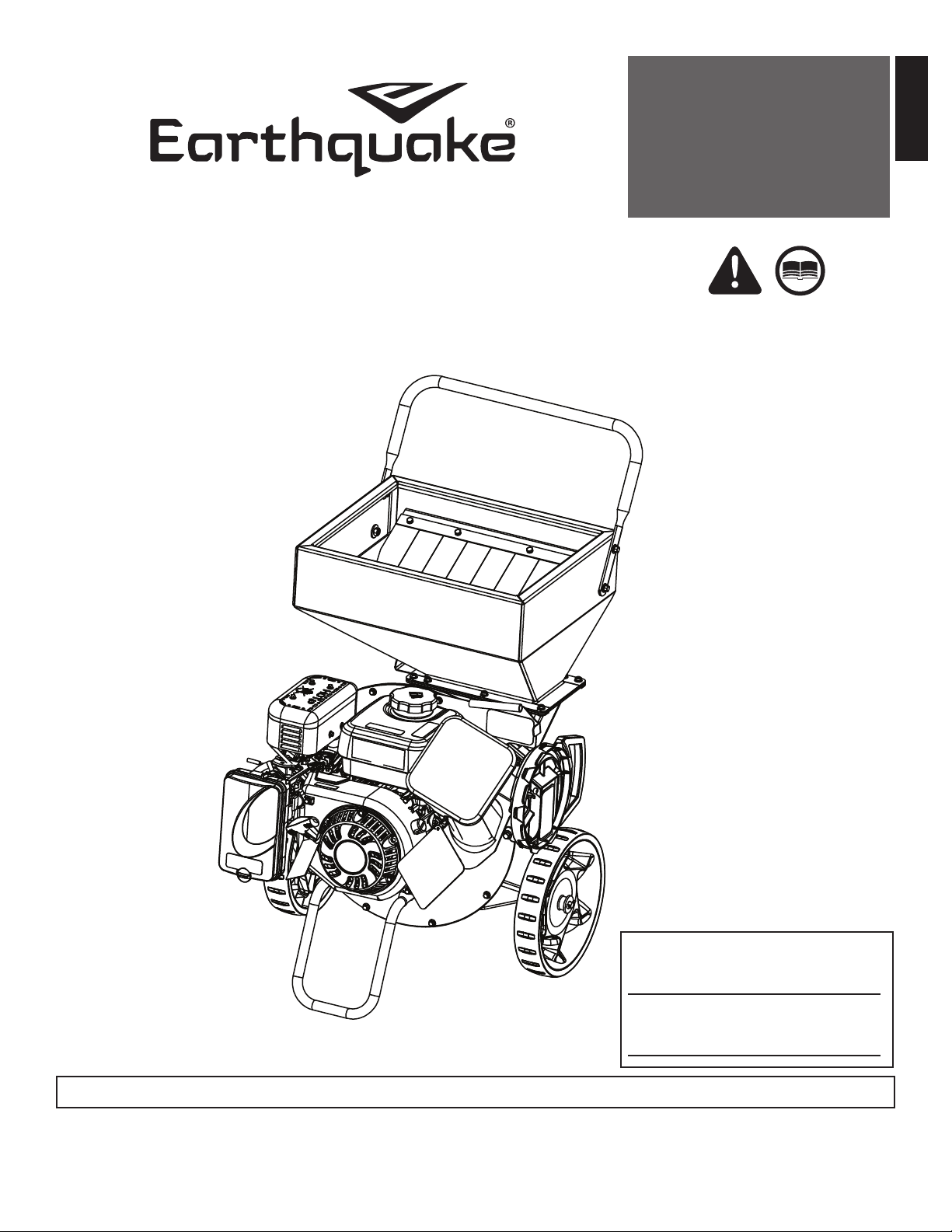
CHIPPER SHREDDER
Model #’s: 18493 / 22752 /
22754 / 30520 / 32013
ENGLISH
SERIAL NO.
DATE OF PURCHASE:
THIS INSTRUCTION BOOKLET CONTAINS IMPORTANT SAFETY INFORMATION. PLEASE READ AND KEEP FOR FUTURE REFERENCE.
Get parts or technical assistance online at
www.GetEarthquake.com or call (800) 345-6007
© 2018 Ardisam
All Rights Reserved
P/N: 32409
REV 1: 08/29/2018
Page 2
Owner’s Manual
CHIPPER SHREDDER
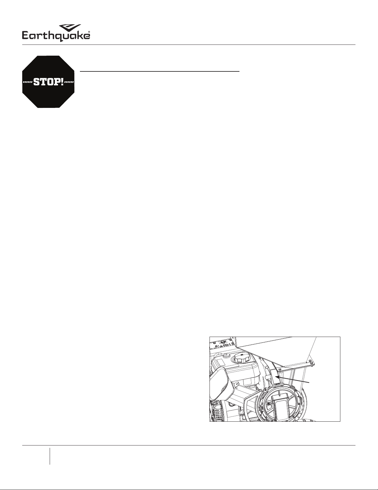
STOP! ACTIVATE YOUR WARRANTY BEFORE USE
All products must be registered within 30 days from the date of purchase in order to be covered under
warranty. For more information regarding Warranty and Registration please review the Warranty and Registration terms and conditions expressed in the warranty insert.
INTRODUCTION
Thank you for purchasing your product from Earthquake®. We have worked to ensure that this product meets the highest standards for usability and durability. With proper care, your purchase will provide many years of service.
Please read this entire manual before installation and use. Earthquake® reserves the right to change, alter or improve the product
and this document at any time without prior notice. Due to continuous product improvements, product images may not be exact.
Some assembly may be required.
Read and keep this manual for future reference. This manual contains important information regarding safety, assembly, operation
and maintenance. The owner must be certain that all the product information is included with the unit. This information includes
the manual, the replacement parts and the warranties. This information must be included to make sure state laws and other laws
are followed. All persons to whom rent/loan this unit must have access to and understand this information. This manual should
remain with the product even if it is resold.
CONTENTS
Introduction/Contents ..................................................................................................................................................................................................................2
Bolt Identication Chart ................................................................................................................................................................................................................3
Warnings and Safety Precautions ..........................................................................................................................................................................................4-9
Features ............................................................................................................................................................................................................................................10
Specications ..................................................................................................................................................................................................................................11
Unpacking and Assembly ................................................................................................................................................................................................... 12-14
Operation .................................................................................................................................................................................................................................. 15-16
Maintenance and Storage ................................................................................................................................................................................................... 17-19
Troubleshooting and Repair ...............................................................................................................................................................................................20-22
REGISTRATION AND SERVICE
Record the product model number and serial number in the
space provided for easy reference when ordering parts or
requesting technical support. Excluding emissions-related
warranty items, the warranty is valid only if the completed
registration is received by Ardisam within 30 days of purchase. You can register your warranty online by visiting www.
GetEarthquake.com, or by mailing it to: Ardisam, 1160 8th
Avenue, Cumberland, WI 54829. You may also call our Customer Service department at (800) 345-6007 Mondays through
Fridays from 8 a.m. to 5 p.m. CST.
Serial
Number
Decal
2
Get parts online at www.GetEarthquake.com or Call 800-345-6007 M-F 8-5 CST
Page 3
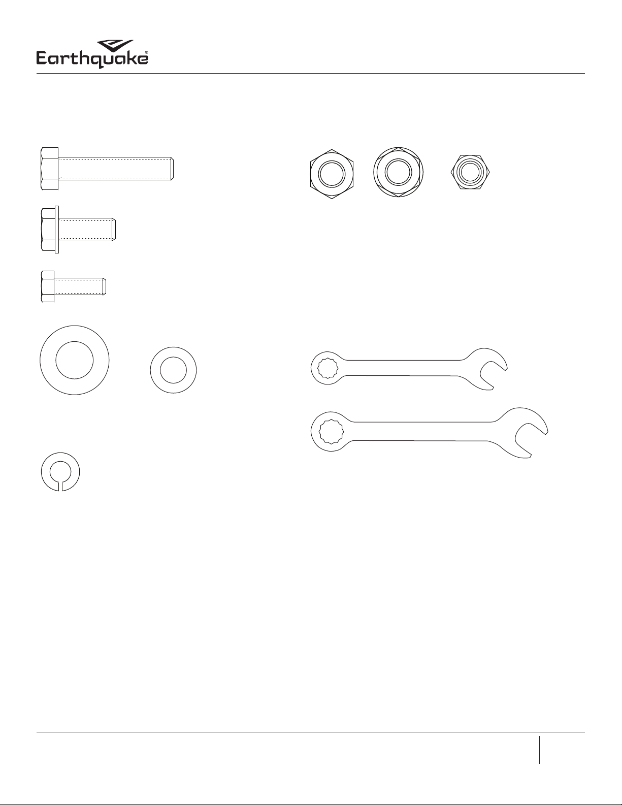
BOLT IDENTIFICATION CHART
Bolts shown are for size reference only. Extra hardware may be
included in the parts bag.
(A)
M8 x 40 MM Bolt
Qty 4
Owner’s Manual
CHIPPER SHREDDER
(B)
M8 x 20 MM Flange Bolt
Qty 4
(C)
M6 x 16 MM Bolt
Qty 3
(D)
12 X 24 MM Washer
Qty 2
(F)
M6 Spring Lock Washer
Qty 3
(E)
M8 Washer
Qty 12
(G)
M8 Nut
Qty 8
(H)
M8 Nyloc Nut
Qty 3
(I)
M6 Nut
Qty 3
TOOLS NEEDED - NOT INCLUDED
8 MM Wrench - Qty 1
10 MM Wrench - Qty 1
Get parts online at www.GetEarthquake.com or Call 800-345-6007 M-F 8-5 CST
3
Page 4
Owner’s Manual
CHIPPER SHREDDER
WARNINGS AND SAFETY PRECAUTIONS
OWNER’S RESPONSIBILITY
Accurate assembly and safe and eective use of the machine is
the owner’s responsibility.
• Read and follow all safety instructions.
• Carefully follow all assembly instructions.
• Maintain the machine according to directions and
schedule included in this Earthquake® operator’s manual.
• Ensure that anyone who uses the machine is familiar with
all controls and safety precautions.
SPECIAL MESSAGES
Your manual contains special messages to bring attention to
potential safety concerns, machine damage as well as helpful
operating and servicing information. Please read all the information carefully to avoid injury and machine damage.
NOTE: General information is given throughout the manual
that may help the operator in the operation or service of the
machine.
This symbol points out important safety instructions
which if not followed could endanger your personal
safety. Read and follow all instructions in this manual
before attempting to operate this equipment.
BEFORE OPERATING EQUIPMENT:
Please read this section carefully. Read entire operating and
maintenance instructions for this product. Failure to follow instructions could result in serious injury or death. Operate the
machine according to the safety instructions outlined here and
inserted throughout the text. Anyone who uses this machine
must read the instructions and be familiar with the controls.
NOTICE
NOTICE INDICATES YOUR EQUIPMENT CAN BE DAMAGED
IF THE SAFETY INSTRUCTIONS THAT FOLLOW THIS SIGNAL
WORD ARE NOT OBEYED.
IMPORTANT
IMPORTANT INDICATES HELPFUL INFORMATION FOR
PROPER ASSEMBLY, OPERATION OR MAINTENANCE OF
YOUR EQUIPMENT.
CAUTION
CAUTION INDICATES A HAZARD WHICH, IF NOT AVOIDED,
COULD RESULT IN PERSONAL INJURY AND/OR PROPERTY
DAMAGE.
WARNING
WARNING INDICATES A HAZARD WHICH, IF NOT AVOIDED,
COULD RESULT IN DEATH OR SERIOUS INJURY AND/OR
PROPERTY DAMAGE.
DANGER
DANGER INDICATES A HAZARD WHICH, IF NOT AVOIDED,
CERTAINLY WILL RESULT IN DEATH OR SERIOUS INJURY
AND/OR PROPERTY DAMAGE.
WARNING
YOU MUST READ, UNDERSTAND AND COMPLY WITH ALL
SAFETY AND OPERATING INSTRUCTIONS IN THIS MANUAL
BEFORE ATTEMPTING TO SETUP AND OPERATE YOUR
MACHINE.
FAILURE TO COMPLY WITH ALL SAFETY AND OPERATING
INSTRUCTIONS CAN RESULT IN LOSS OF MACHINE
CONTROL, SERIOUS PERSONAL INJURY TO YOU AND/OR
BYSTANDERS, AND RISK OF EQUIPMENT AND PROPERTY
DAMAGE. THE TRIANGLE IN THE TEXT SIGNIFIES
IMPORTANT CAUTIONS OR WARNINGS WHICH MUST BE
FOLLOWED.
4
Get parts online at www.GetEarthquake.com or Call 800-345-6007 M-F 8-5 CST
Page 5
GENERAL OPERATING SAFETY
• Read the operating and service instruction manual
carefully. Be throughly familiar with the controls and the
proper use of the equipment. Know how to stop the unit
and disengage the controls quickly.
• Do not operate the equipment without wearing adequate
outer garments and safety goggles. Avoid loose-tting
clothes and use protective footwear that will improve
footing on slippery surfaces.
• Dress appropriately when operating the chipper shredder.
Always wear sturdy footwear and safety goggles. Never
wear sandals, sneakers or open shoes, and never operate
the chipper shredder with bare feet. Do not wear loose
clothing that might get caught in moving parts.
• Never allow children to operate the equipment. Never
allow adults to operate the equipment without proper
instruction.
• Only allow responsible adults, who are familiar with the
instructions, to operate the unit (local regulations can
restrict operator age).
• Keep the area of operation clear of all persons, particularly
small children and pets.
• Always maintain secure footing and solid balance while
starting or operating the chipper shredder. Never lean
directly over the machine.
• Never operate the machine at high transport speeds on
hard or slippery surfaces.
• Operate the machine only in daylight or good articial
light.
• Do not operate the unit while under the inuence of alcohol or drugs.
• Exercise caution to avoid slipping or falling.
• Always wear eye and hearing protection when operating
this unit.
• Keep in mind the operator is responsible for accidents
occurring to other people or property.
• Never operate the machine without proper guards, plates,
or other safety protective devices in place.
• Do not put hands or feet near or under rotating parts or at
inlet or discharge openings.
• Thoroughly inspect where equipment is to be used and
remove all foreign objects.
Owner’s Manual
CHIPPER SHREDDER
DANGER
THE CHIPPER SHREDDER HAS SPINNING BLADES THAT
CAN AMPUTATE HANDS AND FEET. DO NOT PLACE HANDS
OR FEET IN THE HOPPER OR CHIPPER CONE, OR DISCHARGE
CHUTE.
WARNING
COMBUSTIBLE DEBRIS CAN CATCH FIRE. IT IS A VIOLATION
OF CALIFORNIA PUBLIC RESOURCE CODE, SECTION 4442,
TO USE OR OPERATE ENGINE-POWERED PRODUCTS
ON ANY FOREST-COVERED, BRUSH-COVERED, OR GRASS COVERED LAND UNLESS THE EXHAUST SYSTEM IS
EQUIPPED WITH A SPARK ARRESTER, AS DEFINED IN
SECTION 4442, MAINTAINED IN EFFECTIVE WORKING
ORDER. OTHER STATES OR FEDERAL JURISDICTIONS MAY
HAVE SIMILAR LAWS. CONTACT THE ORIGINAL EQUIPMENT
MANUFACTURER, RETAILER, OR DEALER TO OBTAIN A
SPARK ARRESTER DESIGNED FOR USE WITH THIS PRODUCT.
WARNING
THIS UNIT DISCHARGES DEBRIS AT HIGH SPEEDS. ALWAYS
WEAR PROTECTIVE GOGGLES AND DO NOT OPERATE
WITHOUT THE DEBRIS BAG IN PLACE.
DO NOT ALLOW ANYONE IN THE AREA WHILE THE UNIT IS
RUNNING. IF SOMEONE DOES ENTER THE AREA, SHUT THE
UNIT OFF IMMEDIATELY UNTIL THEY LEAVE. ORGANIZE
THE WORK AREA PRIOR TO STARTING WORK.
• Exercise extreme caution when operating on or crossing
gravel drives, walks or roads. Stay alert for hidden hazards
or trac.
• Never allow bystanders near the unit while running.
• Do not put hands or feet near rotating parts or under the
machine. Keep clear of the discharge opening at all times.
• Always operate the chipper shredder outdoors, on a rm,
level, earthen or grassy surface where the unit will be
stable and stay in position. Never attempt to operate the
unit on a slope, or on a wet or slippery surface where you
could slip and fall toward the chipper cone or hopper
openings.
• If the machine should start to vibrate abnormally, stop
the engine (motor) and check immediately for the cause.
Vibration is generally a warning sign of trouble.
Get parts online at www.GetEarthquake.com or Call 800-345-6007 M-F 8-5 CST
5
Page 6

Owner’s Manual
CHIPPER SHREDDER
• Do not operate without the debris bag in place because
this unit discharges debris at high speeds. If the unit is
operated on hard ground, asphalt, concrete, or other hard
surfaces without the collection bag in place. Material can
ricochet o of the hard surface and cause an unsafe condition for users and bystanders.
• Always obey the size limitations for tree limbs and branches stated in the Waste Materials Guide portion of this
manual.
• Never leave the machine running unattended. Always turn
o the engine, wait for the rotor to come to a complete
stop, and disconnect the spark plug before leaving the
area. Always move the unit to a safe storage area when
not in use.
• Never direct discharge material toward anyone. Avoid discharging material against a wall or obstruction. Material
may ricochet back toward the operator.
• Always stand to the side of the chipper cone when feeding tree limbs and branches into the unit, as tree limbs,
branches, and harder woods may kick back while being
chipped.
• Always keep hands out of the chipper cone and shredder
hopper when feeding materials. Never wrap ngers tightly
around branches as you are feeding them into the unit,
as a sudden inward surge could pull your hands and arms
into the unit.
• Never allow material to build up in the discharge area or
shredding chamber, as this may cause new material being
fed into the machine to kickback with sucient force to
injure you or other bystanders.
• Never allow material to build up around the engine during
chipper shredder operation. This could result in a re, or
overheating of the engine.
to tip over, and reaching to steady the unit could result in
accidental insertion of your hands into the chipper cone
or shredder hopper areas.
• Never continue to operate the machine if it starts making
unusual noise or vibration. Shut the engine o immediately, allow the rotor to stop, disconnect the spark plug wire
and secure the wire away from the spark plug. Inspect
the unit for any signs of damage or foreign material in the
chipping or shredding areas. Remove any solid material
that may be preventing the unit from operating properly.
• Never attempt to clear clogs from the chipper cone, shredder hopper or discharge chute while the unit is running.
Always shut the engine o, allow the rotor to come to a
complete stop, and remove the spark plug wire from the
spark plug before removing excess materials.
• Never attempt to perform any maintenance, repairs, or attachment of accessories while the unit is running. Always
shut the unit o, allow the rotor to come to a complete
stop, and remove the spark plug wire from the spark plug
before beginning these activities.
• Always make sure that the shredding chamber, shredder
hopper, and chipper cone are empty before starting the
unit after it has been idle. Attempting to start the unit with
material in these areas could cause the engine starting
cord to stop suddenly, injuring your hand and ngers, or
toppling the unit over. Vibration is generally a warning
sign of trouble.
• Use only attachments and accessories approved of by the
manufacturer of the machine.
• Make sure chipper shredder is free of debris before starting the engine.
• Never attempt to make any adjustments while the engine
is running.
• Take all possible precautions as recommended by the
manufacturer when leaving the machine unattended.
• Do not overload the machine by attempting to chip or
shred any material beyond manufacturers recommendations.
• Use extreme caution when reversing or pulling the machine towards you.
• Do not change the engine governor settings or overspeed
the engine.
• Never attempt to reposition or move the chipper shredder
unit while it is running. Doing so could cause the machine
6
Get parts online at www.GetEarthquake.com or Call 800-345-6007 M-F 8-5 CST
• After striking a foreign object, stop the engine (motor),
remove spark plug wire, and wait for all moving parts to
come to a complete stop. Thoroughly inspect the machine
for any damage, repair the damage before restarting and
operating the machine.
• Start the engine or switch on the motor carefully according to the manufacturers instructions. Keep hands and
feet away from inlet and discharge areas.
• Never pick up or carry the machine while the engine is
running.
Page 7
ENGINE SPECIFIC SAFETY
• Before cleaning, repairing, or inspecting, shut o the
engine and make certain that all moving parts have come
to a complete stop. Disconnect the spark plug wire and
secure the wire away from the spark plug to prevent accidental starting.
• Stop the engine (motor) when leaving the operating
position and when making any repairs, adjustments and
inspections.
MAINTENANCE AND STORAGE
• Keep machine, attachments, and accessories in safe working condition.
• Check engine mounting bolts and other hardware at frequent intervals for proper tightness to be sure the equipment is in safe working condition.
• Never store machine with fuel in the fuel tank inside a
building where ignition sources are present, such as hot
water and space heaters, clothes dryers and the like. Allow
the engine to cool before storing in any enclosure.
• Always refer to the operator’s manual for important details
if the machine is to be stored for an extended period.
• If the fuel tank has to be drained, do this outdoors.
• Follow the manufacturer’s recommendations for safe loading, unloading and storage of machine.
PREVENTING CARBON MONOXIDE POISONING
• Always start and run engine outdoors. Do not start or run
engine in an enclosed area, even if doors or windows are
open.
• Never try to ventilate engine exhaust indoors. Carbon
monoxide can reach dangerous levels very quickly.
• Never run engine outdoors where exhaust fumes may be
pulled into a building.
• Never run engine outdoors in a poorly ventilated area
where the exhaust fumes may be trapped and not easily
taken away. (Examples include: in a large hole or areas
where hills surround your working area.)
• Never run engine in an enclosed or partially enclosed area.
(Examples include: buildings that are enclosed on one or
more sides, under tents, car ports or basements.)
• Always run the engine with the exhaust and muer pointed in the direction away from the operator.
Owner’s Manual
CHIPPER SHREDDER
WARNING
ENGINE GIVES OFF CARBON MONOXIDE, AN ODORLESS,
COLORLESS, POISON GAS. CARBON MONOXIDE MAY BE
PRESENT EVEN IF YOU DO NOT SMELL OR SEE ANY ENGINE
EXHAUST. BREATHING CARBON MONOXIDE CAN CAUSE
NAUSEA, FAINTING OR DEATH, IN ADDITION TO
DROWSINESS, DIZZINESS AND CONFUSION. IF YOU
EXPERIENCE ANY OF THESE SYMPTOMS, SEEK FRESH AIR
AND MEDICAL ATTENTION IMMEDIATELY.
IF YOUR MACHINE COMES WITH A SEPARATE ENGINE
MANUAL, BE SURE TO READ AND FOLLOW ALL SAFETY AND
WARNING PRECAUTIONS OUTLINED THERE, IN ADDITION
TO ANY IN THIS MANUAL.
WARNING
FUEL IS HIGHLY FLAMMABLE. TAKE THE FOLLOWING
PRECAUTIONS:
• STORE FUEL IN CONTAINERS SPECIFICALLY DESIGNED FOR
THIS PURPOSE.
• REFUEL OUTDOORS ONLY AND DO NOT SMOKE WHILE
REFUELING.
• ADD FUEL BEFORE STARTING THE ENGINE. NEVER REMOVE
THE CAP ON THE FUEL TANK OR ADD FUEL WHILE THE
ENGINE IS RUNNING OR WHEN THE ENGINE IS HOT.
• IF FUEL IS SPILLED, DO NOT ATTEMPT TO START THE
ENGINE BUT MOVE THE MACHINE AWAY FROM THE AREA
OF SPILLAGE AND AVOID CREATING ANY SOURCE OF
IGNITION UNTIL FUEL VAPORS HAVE DISAPPEARED.
• REPLACE ALL FUEL TANK AND CONTAINER CAPS SECURELY.
• Never point the exhaust muer towards anyone. People
should always be many feet away from the operation of
the engine and its attachments.
• Do not change the engine governor settings or overspeed the engine.
• Do not operate the engine in a conned space where
dangerous carbon monoxide fumes can collect.
GASOLINE FIRES AND HANDLING FUEL SAFELY
• Use extra care in handling gasoline and other fuels. They
are ammable and vapors are explosive.
• When storing extra fuel be sure that it is in an appropriate
container and away from any re hazards.
Get parts online at www.GetEarthquake.com or Call 800-345-6007 M-F 8-5 CST
7
Page 8

Owner’s Manual
CHIPPER SHREDDER
• Prevent re and explosion caused by static electric
discharge. Use only nonmetal, portable fuel containers
approved by the Underwriter’s Laboratory (U.L.) or the
American Society for Testing & Materials.
• Always ll fuel tank outside in a well ventilated area. Never
ll your fuel tank with fuel indoors. (Examples include:
basement, garage, barn, shed, house, porch, etc.) Never
ll tank near appliances with pilot lights, heaters, or other
ignition sources. If the fuel has to be drained, this should
be done outdoors. The drained fuel should be stored in a
container specically designed for fuel storage or it should
be disposed of carefully.
• Never remove the fuel cap or add fuel with the engine
running. Stop engine and allow to cool before lling.
• Do not smoke while refueling or operating engine.
• Never drain fuel from the engine in an enclosed area.
• Always wipe up excess (spilled) fuel from engine before
starting. Clean up spilled fuel immediately. If fuel is spilled,
do not start the engine but move machine and fuel container from area. Clean up spilled fuel and allow to evaporate
and dry after wiping and before starting.
• Allow fuel fumes/vapors to escape from the area before
starting engine.
• Test the fuel cap for proper installation before starting and
using engine.
• Always run the engine with fuel cap properly installed on
the engine.
• During storage, keep machine so gas cap is up.
• Never siphon fuel by mouth to drain fuel tank.
fuel such equipment on a trailer with a portable container,
rather than from a gasoline dispenser nozzle.
BURNS AND FIRES
• The muer, muer guard and other parts of the engine
become extremely hot during the operation of the engine.
These parts remain extremely hot after the engine has
stopped.
PREVENTION OF BURNS AND FIRES
• Never remove the muer guard from the engine.
• Never touch the muer guard because it is extremely hot
and will cause severe burns.
• Never touch parts of the engine that become hot after
operation.
• Always keep materials and debris away from muer guard
and other hot parts of the engine to avoid res.
CHILDREN AND BYSTANDERS
• Tragic accidents can occur if the operator is not alert to
the presence of children and/or bystanders. Never assume
that others will remain where you last saw them.
• Keep the area of operation clear of all persons, especially
small children and pets. Keep children under the watchful
care of a responsible adult.
• Be alert and turn the machine o if children enter the area.
• Before and while moving backwards, look behind and
down for small children.
• Never allow children to operate the machine
• Always have an adult ll the fuel tank and never allow
children to ll the engine.
• Never allow an adult or anyone under the inuence of
drugs or alcohol to ll engine.
• When storing gasoline or equipment with fuel in the tank,
store away from furnaces, stoves, water heaters or other
appliances that have a pilot light or other ignition source
because they can ignite gasoline vapors.
• Never ll containers inside a vehicle or on a truck bed with
a plastic bed liner. Always place containers on the ground
away from your vehicle before lling.
• Remove gas-powered equipment from the truck or trailer
and refuel it on the ground. If this is not possible, then re-
8
Get parts online at www.GetEarthquake.com or Call 800-345-6007 M-F 8-5 CST
Page 9

A
G
A: Warning!
B: Read Owner's Manual Before Operating Machine.
C: Do Not Operate While Others Are Around.
D: Remove Objects that Could Be Thrown By This Machine.
E: Never Operate Machine Up and Down Slopes, ALWAYS
Operate Mower Across Slopes.
F: Beware of Moving and Rotating Parts.
G: Wear Ear and Eye Protection At All Times.
H: Do Not Service or Adjust Moving Parts Unless Engine is
Stopped and Spark Plug Wire is Disconnected.
I: Direction of Rotating Mower Lines.
J: Toxic Fumes —Do Not Operate in Unventilated Areas.
K: Hot Surfaces.
L: Fire Hazards.
M. Do Not Use In Thunderstorms--For severe weather, stop
operation of this machine and seek shelter.
N. Team Lift--For your safety, always have at least two people
when lifting this machine.
O. Never Fit Metal Cutting Parts--Do not attach any metal parts
to the cutting head of this machine.
P. Do Not Operate When Children Or Others Are Around.
B
H
M N
DC
I
O
E
KJ
P
F
L
Owner’s Manual
CHIPPER SHREDDER
SAFETY DECALS
This unit has been designed and manufactured to provide you
with the safety and reliability you would expect from an industry leader in outdoor power equipment manufacturing.
Although reading this manual and the safety instructions it
contains will provide you with the necessary basic knowledge
to operate this equipment safely and eectively, we have
placed several safety labels on the unit to remind you of this
important information while you are operating your unit.
All DANGER, WARNING, CAUTION and instructional messages on your unit should be carefully read and obeyed. Personal bodily injury can result when these instructions are not
followed. The information is for your safety and it is important!
The safety decals below are on your unit.
If any of these decals are lost or damaged, replace them at
once. See your local dealer or contact Earthquake directly for
replacements.
These labels are easily applied and will act as a constant visual
reminder to you, and others who may use the equipment,
to follow the safety instructions necessary for safe, eective
operation.
Get parts online at www.GetEarthquake.com or Call 800-345-6007 M-F 8-5 CST
9
Page 10

Owner’s Manual
CHIPPER SHREDDER
FEATURES AND CONTROLS
CONTROL FUNCTIONS
The information below briey describes the function of individual controls. Operating requires the combined use of several
controls applied in specic sequences. To learn what combination and sequence of controls to use for various tasks see the
OPERATION section.
*For engine features and controls see engine manual.
SHREDDER HOPPER
CHIPPER CONE
FUEL CAP
DEBRIS BAG CONNECTOR
KICKSTAND
CHIPPER CONE/SHREDDER HOPPER
Chipper Cone: The chipper cone is located on the front of the unit next to the engine. Insert branches and tree limbs up to
approximately 3” (7.6 cm) in diameter into the chipper cone. NEVER insert hands past the mouth of the cone.
Shredder Hopper: The shredder hopper is on top of the unit. Leaves and other light waste can be loaded into the shredder hopper.
Nothing over 1/2 inch in diameter should go into shredder. NEVER insert hands into the hopper .
Debris Bag: Use the debris bag to collect the material discharged from the unit. Do not operate the unit without the debris bag
in place.
10
Get parts online at www.GetEarthquake.com or Call 800-345-6007 M-F 8-5 CST
Page 11

Owner’s Manual
CHIPPER SHREDDER
SPECIFICATIONS
Model # 18493 / 30520 22752 32013 22754
Chipping Capacity Approx. 3” Approx. 3” Approx. 3” Approx. 3”
Shredding Capacity 1/2” x 18” long 1/2” x 18” long 1/2” x 18” long 1/2” x 18” long
Chipping Knives 2 2 2 2
Shredding
Hammers
Waste Reduction
Ratio
Start Type Recoil Recoil Recoil Recoil
Rotor Material Steel Steel Steel Steel
Hopper Dimensions 16.75” x 13.25” 16.75” x 13.25” 16.75” x 13.25” 16.75” x 13.25”
Bag Dimensions 24” x 36” 24”x 36” 24” x 36” 24” x 36”
Limb Chute Ye s Yes Yes Yes
Tire Diameter 11” 11” 11” 11”
Tire Width 2” 2” 2” 2”
Tire Material Rubber Rubber Rubber Rubber
Wheel Type Non-pneumatic Non-pneumatic Non-pneumatic Non-pneumatic
Net Weight 121 lb 118 lb 126 lb 119 lb
2 J-Hammers,
2 Triangle-
Hammers
20:1 20:1 20:1 20:1
2 J-Hammers,
2 Triangle-
Hammers
2 J-Hammers,
2 Triangle-
Hammers
2 J-Hammers,
2 Triangle-
Hammers
Gross Weight 131 lb 131 lb 139 lb 129 lb
Assembled
Dimensions
Boxed Dimensions 32.2” x 23.9” x 23.1” 32.2” x 24.6” x 24.6” 32.2” x 23.9” x 23.1” 32.2” x 23.9” x 23.1”
Vacuum Kit Yes Yes Ye s Ye s
Vacuum
Measurement
Vacuum Air Gate Yes Ye s Yes Yes
Rotor Diameter 14” 14” 14” 14”
Quick Attach
Bag System
ANSI Yes Ye s Yes Yes
25.4” x 29.9” x 51.9” 25.4” x 29.9” x 51.9” 25.4” x 29.9” x 51.9” 25.4” x 29.9” x 51.9”
20” of Water 20” of Water 20” of Water 20” of Water
Yes Ye s Yes Yes
Get parts online at www.GetEarthquake.com or Call 800-345-6007 M-F 8-5 CST
11
Page 12

UNPACKING AND ASSEMBLY
CARTON CONTENTS
TILLER ASSEMBLY
• Manual Parts Bag:
• Hardware Parts Bag:
• A - (4) M8 x 40 MM Bolts
• B - (4) M8 x 20 MM Bolts
• C - (3) M6 x 16 MM Bolts
• D - (2) 12 x 24 MM Washers
• E - (12) M8 Washers
• F - (3) M6 Spring Lock Washers
• G - (8) M8 Nuts
• H - (3) M8 Nyloc Nuts
• I - (3) M6 Nuts
• Cone Cover
• Debris Bag
• Safety Goggles
• (2) Wheels
• Hopper
• Bag Connector
• Bottle of 4-cycle Engine Oil
• Cone
• Chipper Assembly
• Handlebar
• Kickstand
• Hopper Guard
• Bag Support Rod
Owner’s Manual
CHIPPER SHREDDER
G
WHEEL AXLE
E
KICKSTAND
Position the kickstand underneath the engine with the
loop of the kickstand pointing away from the wheel axle.
Using the four M8 x 40 MM bolts (A), eight M8 washers
(E) and four M8 nuts (G), secure the kickstand to the base
plate of the engine.
FIGURE 1
WHEEL AXLE
A
12
COTTER PIN
D
Slide the wheel so that the ange on the tire points out-
ward away from the unit, onto the axle and slide a 12 MM
washer (D) onto the axle against it. Insert the a cotter pin
into the hole in the end of the axle. Bend the cotter pin
over to secure the wheel to the axle. Repeat for opposite
side.
FIGURE 2
Get parts online at www.GetEarthquake.com or Call 800-345-6007 M-F 8-5 CST
Page 13

CHIPPER CONE
H
Position the chipper cone over the three M8 x1.25 threaded
studs protruding from the engine plate, and attach using
three M8 nyloc nuts (H). Rotate cone and cone base away
from engine so cone does not contact engine. Tighten the
three M8 nyloc nuts (H) securely.
Owner’s Manual
CHIPPER SHREDDER
DAMPER
STUD PLATE
I
Remove back four M6 nuts (I) and set nuts and rear stud
plate aside. Loosen front four M6 nuts (I). Note: These will
not need to removed. Install the damper between the stud
plates as shown.
FIGURE 3
HOPPER
STUD PLATES
I
SLOTTED HOLES
Install hopper by sliding slotted holes on the front side of
hopper onto the four studs on the front stud plate with
the previously loosened four M6 nuts (I). Reinstall rear
stud plate and back four M6 nuts (I) that were previously
removed in Figure 4. Tighten all eight M6 nuts (I).
I
FIGURE 4
I
HOPPER GUARD
HOPPER
F
C
Hold the hopper guard so that the rubber guard is directed
down towards the bottom of the hopper. Align the assembly holes with the holes in the hopper. Using the three M6
x 16 MM bolts (C), three M6 spring lock washers (F) and
three M6 nuts (I), secure the hopper guard to the hopper.
Insert the bolts with washers from the outside of the
hopper.
FIGURE 5
FIGURE 6
Get parts online at www.GetEarthquake.com or Call 800-345-6007 M-F 8-5 CST
13
Page 14

HOPPER HANDLE
G
E
Owner’s Manual
CHIPPER SHREDDER
BRACKET
Hold the hopper handle up so that the outer holes in the
handle align with the holes in the hopper and secure with
four M8 x 20 MM bolts (B), four M8 washers (E) and four M8
nuts (G). Insert the screws from the outside of the hopper.
FIGURE 7
TABS
B
TAB
Slide the support rod into the bracket. Rotate the rod so
that it sits below the front tab of the bracket.
FIGURE 8
SUPPORT ROD
Slide the tabs on the debris bag onto the support rod.
Secure the bag connector onto the chipper by rotating
the connector until locked in.
FIGURE 9
14
Get parts online at www.GetEarthquake.com or Call 800-345-6007 M-F 8-5 CST
Page 15

OPERATION
Be sure to read all information in the Safety and Operation
section before attempting to operate this unit. Become familiar
with all of the controls and how to stop the unit.
Check all hardware (bolts, screws, etc) before every use for tightness to be sure machine is in safe working condition.
Upon start-up and shut-down, you may hear the metal-tometal sound of the triangular hammers and J-hammers
positioning themselves on the rotor. This is normal. If this
sound continues after the machine has reached full speed,
contact your dealer or Earthquake for an inspection of the unit.
Overloading the equipment will shorten its life, and can cause
mechanical failures.
CHIPPER OPERATION
The chipper is designed to handle tree limbs and branches up
to approximately 3” (7,6 cm) in diameter. The chipping knives
also permit the processing of course organic matter like corn
stalks. Tree branches must be inserted large-end rst into the
chipper cone. Since occasional kick-backs may occur, always
stand o to the side of the unit. Allow the self-feeding action
of the unit to draw the sticks in.
SHREDDER OPERATION
The shredder is designed to shred light brush, leaves, and
other soft but bulky organic waste. As material (no larger than
1/2 inch in diameter) is loaded into the shredder hopper it is
pulled into the path of the triangular and J-hammers by air
ow.
VACUUM ATTACHMENT (OPTIONAL)
Owner’s Manual
CHIPPER SHREDDER
DANGER
THE EXHAUST FROM THIS PRODUCT CONTAINS CARBON
MONOXIDE GAS. CARBON MONOXIDE IS A COLORLESS,
ORDERLESS AND TASTELESS GAS THAT CAN CAUSE
DIZZINESS, NAUSEA, UNCONSCIOUSNESS OR EVEN BRAIN
DAMAGE AND DEATH IF INHALED FOR PROLONGED
PERIODS.
OPERATE THE UNIT OUTDOORS IN A WELL VENTILATED
LOCATION ONLY. KEEP CHILDREN, PETS AND BYSTANDERS
AW AY.
WARNING
TO AVOID SERIOUS PERSONAL INJURY FROM ROTATING
CUTTING BLADES, KEEP HANDS OUT OF INLET WHILE
MACHINE IS RUNNING.
GASOLINE IS HIGHLY FLAMMABLE AND MUST BE HANDLED
WITH CARE. NEVER FILL THE TANK WHEN THE ENGINE IS
STILL HOT FROM RECENT OPERATION. DO NOT ALLOW
OPEN FLAME, SMOKING OR MATCHES IN THE AREA. AVOID
OVER-FILLING AND WIPE UP ANY SPILLS.
DO NOT USE GASOLINE CONTAINING METHANOL,
GASOHOL CONTAINING MORE THAN 10% ETHANOL,
GASOLINE ADDITIVES OR WHITE GAS BECAUSE ENGINE/
FUEL SYSTEM DAMAGE COULD RESULT.
IMPORTANT
ENGINE IS SHIPPED FROM FACTORY WITHOUT OIL. YOU
MUST ADD ENGINE OIL BEFORE STARTING ENGINE.
In addition to the chipper cone and hopper, loose debris may
be processed by the Vacuum hose adapter kit. Leaves may be
raked directly into the leaf tray where vacuum action will draw
them into the shredder. For hard-to-reach areas, the nozzle
and hose assembly may be used. The strength of the Vacuum
may be changed using the rotating sleeve on the nozzle.
The optional Tazz vacuum kit and can be ordered by
contacting Earthquake customer service or ordering online at
getearthquake.com as listed below.
OPERATING LOCATION
Select an area with rm, level ground, covered by dirt or grass.
Do not operate on wet or slick surfaces, or near bystanders.
Locate and organize the materials to be processed so that you
don’t have to walk in front of the inlet or discharge openings,
and so you have adequate room to work safely.
Get parts online at www.GetEarthquake.com or Call 800-345-6007 M-F 8-5 CST
ADDING OIL
Refer to engine manual for information on adding oil.
ADDING FUEL
1. Remove the fuel cap. (See Features and Controls)
2. Fill the tank. Do not overll. Leave room in the tank for fuel
expansion. Refer to your engine manual for specic fuel
recommendations.
3. Install and hand tighten the fuel cap.
STARTING THE ENGINE
1. See engine manual for start up instructions.
2. Ensure engine is running full throttle before beginning
15
Page 16

Owner’s Manual
CHIPPER SHREDDER
chipping operation. On some engines, the throttle may
not be adjustable.
STOPPING THE ENGINE
See engine manual for shut down procedure.
PROCESSING MATERIALS
Most materials to be processed can be handled more eciently by following these tips.
CHIPPING TIPS:
• Prune branches down close to the main branch to make
feeding them into the chipper cone easier.
• Large, hard, dried tree branches that resist chipping can
be processed by rotating them as you alternately insert
and retract them.
• If the material to be chipped is extremely hard, kicks back
forcefully when being fed into the chipper cone, or cannot
be easily controlled, remove the material immediately and
set it aside.
• If additional force is required to insert materials into the
chipper, the blades probably need to be sharpened.
Consult the Troubleshooting and Repair section of this
manual, or see your authorized dealer.
• Maintain control of the materials you are feeding to prevent them from whipping around.
• Do not insert short pieces of material into the chipper
cone by hand. Use a larger piece of material to feed them
into the chipper cone.
SHREDDING TIPS:
• Don’t overload the shredder by dumping large volumes of
material into the hopper opening.
• Alternate loads of wet and dry material to prevent the
discharge from becoming plugged.
• Never use any object to force material into the shredding
chamber. It could get caught in the shredding hammers
and damage the unit.
OPERATION TYPE OF WASTE PERMITTED SIZE LIMITATIONS NOTES
Shredding Dry or moist organic material
including leaves, plants, owers, fruits, or vegetables.
Chipping Long, thicker tree limbs or
small bunches of smaller
sticks grouped together for
ease of handling.
Vacuum Attachment
(Optional Accessory)
Light, loose, dry waste such
as leaves, grass clippings, or
sawdust.
Branches and twigs up to 1/2”
diameter and 18” long.
Tree limbs and branches,
or bundles of small sticks
grouped for easier handling.
Maximum diameter of approximately 3” (7,6 cm).
Small materials that will not
obstruct the vacuum hose.
Alternately chip or shred moist green
waste with dry waste to avoid plugging of the discharge chute.
Process at a feeding rate that allows
the rotor to keep up and maintain a
high rate of speed.
Bulky tree limbs should be pruned
close to the main stem. Always use
a shorter piece of wood to push end
pieces into the chipper cone. Never
place hands in the chipper cone.
Never chip very hard or dry materials
such as kiln dried dimensional lumber
(2x4’s etc.) or other building materials.
Never use the chipper to process pressure-treated wood products.
The vacuum is engineered for small,
loose waste and for cleaning around
decorative landscaping and ower
beds. Twigs, wet leaves, and other
bulky materials will clog the hose or
obstruct the shredding chamber.
16
Get parts online at www.GetEarthquake.com or Call 800-345-6007 M-F 8-5 CST
Page 17

Owner’s Manual
CHIPPER SHREDDER
TRANSPORTING AND STORAGE
• Always observe safe refueling and fuel handling practices
when refueling the unit after transportation or storage.
• Never store the unit (with fuel) in an enclosed poorly
ventilated structure. Fuel vapors can travel to an ignition
source (such as a furnace, water heater, etc.) and cause an
explosion. Fuel vapor is also toxic to humans and animals.
• Always use the hopper handle and built-in wheels to
move the chipper shredder. Never lift the unit using the
fuel tank for support. If the unit must be lifted , always
use at least two people, and always grip the unit securely
using the front leg and hopper handle.
• Always follow the engine manual instructions for storage
preparations before storing the unit for both short and
long term periods.
• Always follow the engine manual instructions for proper
start-up procedures when returning the unit to service.
• Never store the unit or fuel container inside where there
is an open ame or pilot light, such as in a water heater.
Allow unit to cool before storing.
STORAGE
Perform engine maintenance and storage measures listed in
the engine owner’s manual. This includes draining the fuel
system, or adding stabilizer to the fuel.
MAINTENANCE
SCHEDULE AND PROCEDURES
The following schedule should be followed for normal care of
your unit.
BEFORE
SAFETY ITEMS
Check for loose
hardware
Check all safety
labels
CHIPPER
MAINTENANCE
ITEMS
Clean debris from
engine and
chipper. **
Inspect/Rotate
Shredding
Hammers
Inspect/Rotate
Chipping Knives
** More often in hot (over 85° F: 30° C) weather or dusty
operating conditions.
EACH
USE
BEFORE
EACH
USE
x
EVERY
5
HOURS
x x
EVERY
5
HOURS
EVERY
25
HOUR
EVERY
25
HOURS
x
x
SPRING
& FALL
x
SPRING
& FALL
NOTE: Do not store a fueled unit in an enclosed structure. (See
Gasoline Fires and Handling Fuel Safety
BEFORE STARTING THE UNIT AFTER IT HAS BEEN STORED:
1. Check all uid levels. Check all maintenance items.
2. Perform all recommended checks and procedures found
in the engine owner’s manual.
3. Allow the engine to warm up for several minutes before
use.
WARNING
AMPUTATION HAZARD. TO AVOID SERIOUS INJURY FROM
ACCIDENTAL STARTING, ALWAYS DISCONNECT THE SPARK
PLUG WIRE AND SECURE IT AWAY FROM THE SPARK PLUG
WHEN SERVICING THE UNIT.
Get parts online at www.GetEarthquake.com or Call 800-345-6007 M-F 8-5 CST
ENGINE MAINTENANCE
Refer to the engine manual included in your parts packet for
information on engine maintenance. Your engine manual provides information and a maintenance schedule for performing
the following tasks:
1. Check oil level before each use or after every 8 hours of
operation.
2. Change oil after rst 5-8 hours of operation. Change oil
while engine is warm. Rell with new oil of recommended
grade.
4. Check spark plug seasonally or every 100 hours of operation.
5. Service air cleaner.
6. Keep engine and parts clean.
7. Check engine and equipment often for loose nuts and
bolts, keep these items tightened.
17
Page 18

Owner’s Manual
CHIPPER SHREDDER
CHECK FOR LOOSE HARDWARE
Service Interval: Every 5 hours; every spring and fall.
Inspect the unit, checking for loose hardware or components.
Pay special attention to the hardware attaching the chipper
cone, hopper, axle, and front leg.
CHECK SAFETY LABELS
Service Interval: Every spring and fall.
Check that the safety labels are in place and undamaged.
Replace any damaged or missing decals.
INSPECT CONE, HOPPER AND GUARDS
Service Interval: Every spring and fall.
Check that the chipper cone, shredder hopper, and discharge
guards are in place, undamaged, and secure. Replace any
damaged or missing parts.
CLEAN DEBRIS FROM ENGINE AND CHIPPER
Service Interval: Before each use and every 100 hours.
The engine requires air ow to cool itself and for combustion.
Before each use, clean any debris from the unit especially from
around the air shroud intake, air lter, and muer. Every 100
hours, remove the engine air shroud and clean out any debris
from the engine cooling ns SEE FIGURE 10. We recommend
having this service performed by an authorized repair center.
AIR
SHROUD
INTAKE/
AIR FILTER
COOLING FINS
MUFFLER
DEBRIS OFTEN GATHERS IN
THIS AREA
FIGURE 10
INSPECT / ROTATE SHREDDING HAMMERS
Service Interval: Every 25 Hours, or As Necessary
The shredding hammers of this unit can be rotated to provide
a new cutting surface as required. The triangular hammers
can be rotated twice, then ipped over for a total of 6 sharp
cutting surfaces. The J-hammers can be ipped over once. To
inspect the shredding hammers:
1. Disconnect the spark plug wire and secure it away from
the spark plug. SEE FIGURE 14 (on page 19).
2. Remove the small circular access panel (B) from the back
of the shredder housing. SEE FIGURE 11.
3. Inspect the cutting edges of the triangular hammers (A)
and J-hammers (A). SEE FIGURES 11 AND 12.
To rotate or replace the shredding hammers, see the Troubleshooting and Repair section.
ACCESS PANEL
J-HAMMER
WEAR AREA
FIGURE 11
TRIANGULAR-HAMMER
WEAR AREA
FIGURE 12
18
Get parts online at www.GetEarthquake.com or Call 800-345-6007 M-F 8-5 CST
Page 19

INSPECT CHIPPING KNIVES
Service Interval: Every 25 hours, or as necessary
CAUTION
Owner’s Manual
CHIPPER SHREDDER
The chipping knives of this unit can be rotated or sharpened
to provide a new cutting surface as required. When inspecting the knives be careful to avoid touching the sharpened
edges. To inspect the chipping knives:
1. Disconnect the spark plug wire and secure it away from
the spark plug. SEE FIGURE 14.
2. Remove the nuts securing the chipper cone to the front
of the chipper. Remove the chipper cone (A) to access the
knives. SEE FIGURE 13.
3. Using the recoil starter, slowly pull the starter rope to
rotate the rotor into position so the blades can be seen.
To sharpen or replace the chipper knives, see the Troubleshooting and Repair section.
CHECK / CHANGE ENGINE AIR CLEANER
Service Interval: Every 25 hours
The engine air cleaner assembly should be opened, inspected,
and the lter element replaced every 25 hours, or as required if
debris has built up in the assembly.
To replace the air lter, see engine manual.
FOR THE SAFETY OF THE USER, AND TO MAXIMIZE THE
LIFE OF THE ENGINE, IT IS CRUCIAL TO TAKE TIME TO
CHECK THE CONDITION OF THE ENGINE. PROBLEMS MUST
BE CORRECTED BEFORE OPERATING.
AVOID INJURY! ENGINE OIL IS HAZARDOUS TO YOUR
HEALTH. DISPOSE OF OIL APPROPRIATELY. USE A SAFE
DISPOSAL/RECYCLING CENTER.
CHIPPER CONE
FIGURE 13
REPLACE SPARK PLUG
Please contact your authorized repair center to perform
this service.
OIL MAINTENANCE
Refer to engine manual for oil maintenance.
SPARK PLUG
FIGURE 14
Get parts online at www.GetEarthquake.com or Call 800-345-6007 M-F 8-5 CST
19
Page 20

Owner’s Manual
CHIPPER SHREDDER
TROUBLESHOOTING
While normal care and regular maintenance will extend the life of your equipment, prolonged or constant use may eventually
require that service be performed to allow it to continue operating properly.
The troubleshooting guide below lists the most common problems, their causes, and remedies.
See the information on the following pages for instructions on how to perform most of these minor adjustments and service
repairs yourself or by your local authorized repair center.
PROBLEM CAUSE REMEDY
Engine will not start. 1. Out of fuel.
2. Spark plug wire disconnected.
3. Engine controls not set correctly.
4. Spark plug fouled.
5. No compression. Recoil starter pulls
with no resistance.
6. No spark. Ignition problems.
7. Old or stale fuel.
Engine exhaust is black. 1. Dirty air lter
2. Choke closed.
Engine runs but no material is
discharged.
Excessive branch vibration
when chipping materials.
Unusual noise or vibration
when chipping materials.
Vacuum not working. 1. Hopper gate not closed.
1. Discharge chute clogged.
2. Engine not running at full speed.
1. Chipper knives dull.
2. Tree limbs are extremely hard or dried
out.
1. Rotor overloaded with material.
2. Hammers are broken, bent, or loose.
3. Hammers frozen in place.
2. Cone cover not installed.
3. Hose not attached properly.
4. Hose obstructed or damaged.
5. Engine not running at full RPM.
1. Add Fuel.
2. Reconnect spark plug wire as recommended in engine manual.
3. Refer to STARTING in the engine manual.
4. Remove spark plug. Clean/replace as
recommended in engine manual.
5. See your authorized service center.
6. See your authorized service center.
7. See your authorized service center.
1. Replace air lter. See engine manual.
2. Open choke.
1. Clean out debris.
2. Set throttle control to FAST if equipped.
For xed throttle engines see your
authorized service center.
1. Sharpen/Replace chipper knives.
2. Material is not suitable for chipping.
1. Allow unit to clear itself before adding
more material to the hopper.
2. Check assembly. Tighten or replace as
necessary.
3. Check for obstructions and debris. Repair
or replace as necessary.
1. Slide gate to closed position.
2. Allow material to dry.
3. Attach hose per instructions (See Hose
Kit).
4. Clear blockage or replace.
5. Set throttle control to FAST if equipped.
For xed throttle engines see your
authorized service center.
20
Get parts online at www.GetEarthquake.com or Call 800-345-6007 M-F 8-5 CST
Page 21

REPAIR
ROTOR REMOVAL
NOTE: The rotor does not need to be removed to change the
hammers and knives. However, the removal and installation of the knives will be easier with the rotor removed.
NOTE: If using a unit that has socket head bolts with no locking plates on them, the hardware will need to be upgraded to
new hardware kit.
Owner’s Manual
CHIPPER SHREDDER
WARNING
CUTTING HAZARD. TO AVOID SERIOUS INJURY, AVOID
CONTACTING THE SHARP CUTTING EDGES OF THE
CHIPPING KNIVES.
To remove the rotor from the drive shaft:
1. Turn the engine o and wait for all moving parts to stop.
2. Disconnect the spark plug wire and secure it away from
the spark plug. SEE FIGURE 15.
3. Detach the rotor housing and hopper from the rotor
plate. SEE FIGURE 16.
4. Bend the side tabs away from the center mounting bolt
and remove the bolt (8).
5. Carefully remove the rotor plate, spacer, and key (10) from
the crankshaft. SEE FIGURE 17.
HAMMER REMOVAL AND INSTALLATION
NOTE: The cutting edges of the shredding hammers may
eventually wear out requiring rotation of the hammer or
replacement if all cutting edges have been dulled.
NOTE: Triangular hammers can be rotated twice after the
rst edge dulls, then ipped over once and rotated again
for a total of six edges. J-hammers can be ipped over
once for a total of two cutting edges.
1. Remove the hammers by rst bending the lock plate
tabs down away from the hex head bolt securing the
hammers. Remove the bolt. SEE FIGURES 18 AND 19
(next page).
NOTE: the assembly sequence of the hardware used to
secure the hammers.
SPARK
PLUG
WIRE
FIGURE 15
ROTOR PLATE
ROTOR HOUSING
FIGURE 16
3/8 X 2” BOLT
KEY
SPACER
2. Inspect the hammers, spacers, and hardware. If the spacer
tube shows signs of wear, replace it. Inspect and ip, or
replace the hammers. The lock plate should always be
replaced when replacing or rotating hammers.
3. Inspect the hammers, spacers, lock plate and bolts. Torque
the bolt to 30-35 ft -lb (41-47 N.m.). The J-hammer on the
Get parts online at www.GetEarthquake.com or Call 800-345-6007 M-F 8-5 CST
ROTOR PLATE
FIGURE 17
21
Page 22

opposite side of the rotor faces outward for balanced rotation. Two faces of the bolt should align in parallel with the
lock plate tabs.
NOTE: We recommend the use of high-strength thread
locker on mounting bolts.
4. Bend the lock plate tabs up to secure the bolt and preventing rotation. The tabs should sit at on a face of the
bolt. SEE FIGURE 18.
5. Repeat for all hammers.
CHIPPING KNIFE REMOVAL AND INSTALLATION
To inspect or replace the chipping knives:
1. Bend the lock plate tabs away from the bolts securing the
chipping knives.
2. Remove the two bolts and the chipping knife. SEE
FIGURE 20.
Owner’s Manual
CHIPPER SHREDDER
LOCK PLATE
TABS
FIGURE 18
ROTOR PLATE
TRIANGULAR-HAMMER
3. Inspect or replace the chipper knife.
4. Reinstall the chipper knife and tighten the bolts to 18-20
ft-lb (24-27 N.m.). Ensure that the knife is sitting squarely
against the stop that has been formed into the rotor. If it is
not sitting square, the knives will perform as if they are extremely dully. Always use a new lock plate when installing
knives. Two of the bolt faces should align in parallel with
the lock plate tabs.
Note: We recommend the use of high-strength thread locker
on mounting bolts.
5. Bend the lock plate tabs up to prevent bolt rotation. The
tabs should sit at on a face of the bolt. SEE FIGURE 18.
INSTALL THE ROTOR ON THE CRANKSHAFT
To install the rotor on the crankshaft:
1. Replace the rotor onto the crankshaft, careful to replace
the spacer and key. SEE FIGURE 17.
2. Torque the mounting bolt to 30-35 ft-lb (41-47 N.m.).
3. Bend the lock plate tabs up to secure the mount bolt and
prevent rotation. The tabs should sit at on the face of the
bolt.
M10 X 50 MM
BOLT
LOCK
PLATE
M8 X 16 MM
BOLT
LOCK
PLATE
SPACERS
J-HAMMER
FIGURE19
KNIFE
ROTOR PLATE
FIGURE 20
4. Reinstall rotor housing and hopper. SEE FIGURE 16.
22
Get parts online at www.GetEarthquake.com or Call 800-345-6007 M-F 8-5 CST
Page 23

NOTES:
Owner’s Manual
CHIPPER SHREDDER
Get parts online at www.GetEarthquake.com or Call 800-345-6007 M-F 8-5 CST
23
Page 24

ARDISAM, INC.
1160 Eighth Avenue
PO Box 755
Cumberland, WI 54829
Phone: (800) 345-6007
Fax: (715) 822-2124
www.GetEarthquake.com
 Loading...