

Page 1

Page 1
1.0 TransEagle® Software Guide
1.1 Introduction
The TransEagle® Network software package works hand-in-hand with the Eagle
Series Printer to provide a robust remote print control environment. It provides remote
print control to up to five Eagle printers using a 10 Base T, 10Mb/sec connection
networking model. The network connectivity model employed with TransEagle® is
comprised of TCP/IP and FTP client/server network “channels”. Connectivity is
provided via a single network cable connection.
TransEagle® can be installed on your PC from the CD that comes with your system. It
is designed to perform best with a Pentium 90Mhz processor or better running
Windows 95/98/NT4/2000. You must also have a 10 base T Network Interface Card
(Ethernet Card) installed on your PC. (Note: the Ethernet connection on the Eagle is
now standard. Some older printers may not have the Ethernet option installed and
would need to be upgraded before you could connect your Eagle to your PC using the
TransEagle® software).
This section is current for version 3.10 of TransEagle®.
1.2 Getting Connected
Before running TransEagle® the first time, make sure the following configurations are
in place.
1.2.1 Cable connection
If a direct connection is desired between the host system and a single Eagle
printer the use of a crossover 10Mb/sec network cable complete with RJ-45
connectors is required to effect the connection. Plug one end of the crossover
cable into the Eagle printer and the other end of the cable into the host system
Network Interface Card.
If multiple Eagle printers are to be connected then a network hub or other
routing device must be utilized. Please refer to the topology and connection
scheme provided by the hub manufacturer for host and Eagle hardware
connectivity. Typically one would attach straight network cables between the
hub and or router directly to each Eagle printer. The host system would then
attach to the hub or to another concentrator device that provides a path to the
Eagle hub and or individual systems etc.
10/30/2001
Manual Part Number 900-00027-001
Page 2
Page 2
1.2.2 Eagle Network settings
You will need to choose an IP Address for your Eagle. If you are using a direct
connection to your PC, then we recommend that you use the default address of
192.168.2.3. If your Eagle already has this address, then you are ready to go
to 1.2.3. To check your Eagle’s current IP address, press Ctrl-W on the Eagle’s
handheld terminal to bring up the network screen (see figure 1.2.1).
IP: 192 . 168 . 2 . 3
TPC Port: 4000
NICUp FTPUp TCPUp
Figure 1.2.1 Network Screen on Eagle
If you are connecting to more that one Eagle, then you will need to give a
different address to each Eagle. Choose numbers with the last digit close to
each other. For example, Eagle 1: 192.168.2.3, Eagle 2: 192.168.2.4, Eagle 3:
192.168.2.5, etc.
Finally, if you are connecting to a PC that is already a part of a local office
network, then you will need to check with your network administrator to find an
available IP address for your Eagle printer that fits into your existing network IP
scheme.
Once you choose an IP address for your Eagle, you will need to change the
Eagle to the new address, if necessary, by following these steps:
1. Press Ctrl-W to jump to the network screen (see figure 1.2.1).
2. Press EDIT (F4) twice to bring up a blinking block cursor beside the IP
address.
3. Press Ctrl-X to clear the existing address.
4. Type the IP address you want to change to. You must supply the period
between numbers.
5. Press ENTER once.
6. Press “Y” (yes) to confirm.
7. Press ENTER again.
The new IP address is saved automatically to the Eagle and will remain even
after the power to the Eagle is turned off.
10/30/2001
Manual Part Number 900-00027-001
Page 3
Page 3
1.2.3 Network Configuration on Your PC
Now, you will need to choose an IP address for your PC. If you are already on
a local office network and you have obtained and entered an IP address on the
Eagle as described above, you shouldn’t need to make any changes to your
PC. Skip to 1.2.4. Otherwise, if you are not already on a local network, then
simply choose an address whose last number is close to that of the Eagle(s). If
you are using the default address of 192.168.2.3 on your Eagle, for example,
then it is recommended that you choose something like 192.168.2.1 for your
PC.
Change network configuration settings and specify an IP address as follows:
1. Right click the Network Neighborhood icon on your desktop and go to “Properties”.
If you do not have a Network Neighborhood icon on your desktop, click Start>Settings->Control Panel->Network or Network Settings.
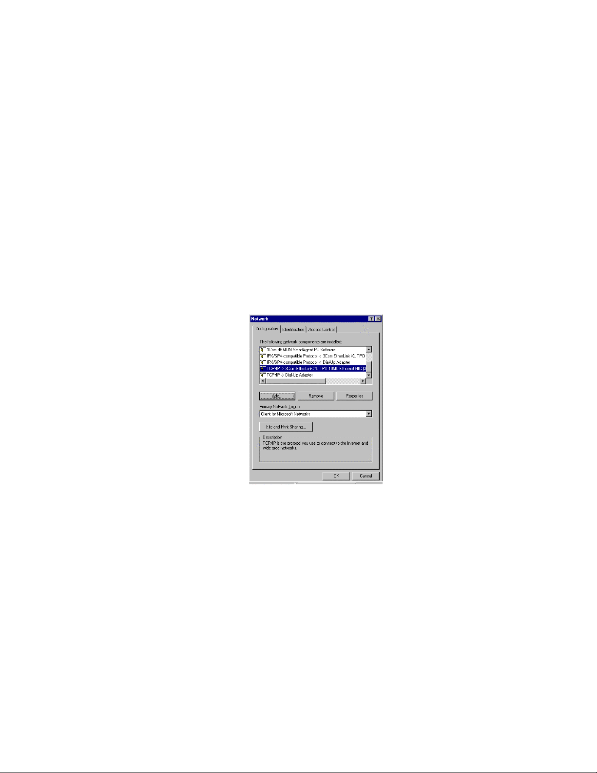
2. Find the listing with TCP/IP. Depending on what version of Windows you are
running, it may be under Configuration, Protocol, or Local Area Network.
Figure 1.2.2 Example of Network Configuration Dialog on PC
3. Click on the TCP/IP Protocol from the list that is bound to your Eagle (i.e.
the TCP/IP item with your Ethernet card shown beside it or, on some
systems, simply “TCP/IP” by itself). Figure 1.2.2 shows an example of what
the dialog may look like with TCP/IP selected.
4. Click on the “Properties” buttons.
5. Select the “IP Address” tab on the TCP/IP properties dialog (see figure 1.2.3
for an example of what this dialog may look like).
6. Click the “Specify an IP Address” radio button.
7. Enter the IP address you chose for your PC in the “IP address” text box.
8. Enter a subnet address mask in the appropriate box. Use 255.255.255.0.
9. Click “OK”
10/30/2001
Manual Part Number 900-00027-001
Page 4

Page 4
10. Click “OK” again at the main network screen.
11. If asked to re-boot your computer, do so at this time
Figure 1.2.3 Example of TCP/IP Properties Dialog on Your PC
1.2.4 Configuring TransEagle® and Making a Connection
Once you have run the Leader Installation CD, you will notice that an icon for
TransEagle® will have been added to your desktop (also to the start menu).
Double-click on the TransEagle® icon to launch the program. You should
immediately be given a dialog asking if you would like to re-establish your
network connection. Since this is the first time you will be attempting to make a
connection to your Eagle, select NO. The TransEagle® program is shown in
figure 1.2.4.
Figure 1.2.4 TransEagle® Program
Note that the state of the Network->Enabled radio button on your screen will
currently be disabled since you have not yet made a connection. Click the
“Properties” button under Network. You will see the dialog shown in figure
1.2.5.
10/30/2001
Manual Part Number 900-00027-001
Page 5

Page 5
Figure 1.2.5 TransEagle® Network Properties
Type the IP address on the Eagle Printer into Printer 1. This value can be
found by pressing Ctrl-W on the handheld terminal (see figure 1.2.1). Type the
IP addresses of any additional printers (up to 5) you will be networking to into
Printer 2-5.
Before clicking OK, check that your network cable is plugged into both the
Eagle and the PC and that the Eagle is powered on and has the right IP
address. Click OK. Upon clicking OK, TransEagle® will attempt to connect to
the Eagle(s). You will know in a few seconds if the attempt was successful as
the Network->Enabled radio button will become enabled.
If you still are seeing an hourglass after 10-15 seconds, you most likely have a
network problem. TransEagle® will take about a minute to finally time out and
give you an error indicating that the connection was not successful. If this
happens, go through the configurations of the Eagle and the PC one more time,
double-checking that all the IP addresses are typed in correctly, and that you
have the right type of network cable. For example, if you are connecting
directly from your PC to the Eagle, a common mistake is to use a straight cable
rather that a crossover cable. You can check this by unplugging the cable and
holding the two ends side-by-side to check the wiring. Make sure the ends of
the cable are both facing the same direction and you will be able to recognize a
straight cable by noticing that the colored wires are in the same order on both
ends. If not, then you most likely have a crossover cable. Usually, doublechecking all the configurations and the cable will solve the problem and you will
be able to connect successfully by following this procedure again.
Once you are connected, you will be able to send files directly from
ImageMaster to the Eagle. Simply leave TransEagle® running in the
background, launch ImageMaster and create and send messages at will.
If you close TransEagle® and launch it again at a later time, you will again be
asked if you would like to re-establish your network connections. If you
connected successfully in your last TransEagle® session and all connected
Eagles are powered on and ready, then you merely need to click YES at this
point to re-connect.
10/30/2001
Manual Part Number 900-00027-001
Page 6

1.3 TransEagle® Features and Settings
1.3.1 Communication Data Area
As we have already seen, this area of TransEagle® includes commands related
to the configuration of network connections to Eagle printers.
1.3.1.1 Enabled Radio Button
This non-editable radio button shows the status of TransEagle’s® connections.
If any of the printers you attempted to connect to were successfully connected,
then the radio button will be enabled.
1.3.1.2 Broadcast Checkbox
Check this box to have TransEagle® send messages to all connected Eagles at
one time whenever a message is transferred, either from ImageMaster or
directly from TransEagle® (see below to learn how to transfer files). If
unchecked, then messages will only be transferred to the selected Eagle printer
(see 1.3.1.4).
1.3.1.3 Properties Button
Click this button to set the IP address of all connected Eagles (see figure
1.2.5). You will also see a button on the Eagle IP dialog labeled “Set Printer
Names”. Click this if you wish to be able to give a meaningful name to each
Eagle printer you are connected to. The names appear on each of the printer
buttons in the same area.
1.3.1.4 Printer buttons
These five buttons shows all the printers that you are currently connected to.
Any button that is enabled corresponds to a printer that is connected. Click on
any one of the enabled buttons to select that printer as the current one to send
messages to. See 1.3.1.3 to learn how to give the printers listed on the buttons
meaningful names
1.3.2 Message File Data Area
This area contains commands for selecting files to send to the Eagle.
Page 6
10/30/2001
Manual Part Number 900-00027-001
Page 7

Page 7
1.3.2.1 File Name
This drop-down allows you to select from a list of message files comprised of
the files that reside in the designated message directory for the currently
selected Eagle printer. The directory is called “Eaglex” and is under the
working directory of TransEagle® (where x is the printer number that you
currently have selected). For example, for printer 1 and a standard installation,
that directory is “c:\Leader Corporation\Eagle1”.
If you have “auto” checked in the Transfer Area, then the message will be sent
to the Eagle immediately when you select it from the drop-down. Otherwise,
the message you selected will not be sent until the “Transfer” button is clicked.
All transferred messages that have imbedded bitmap files will automatically
look in the “Graphics” directory under “Eaglex” and transfer those bitmaps to
the Eagle automatically. You will receive an error if any requested bitmaps are
not present in that directory.
1.3.2.2 Print Now Checkbox
Check this to have any transferred message files immediately become the
active print file on the Eagle. If not checked, then files that are transferred are
merely saved to the disk for later recall.
1.3.2.3 Temp Msg Checkbox
Check this to have files that are sent over for immediate printing not be saved
to the Eagle disk. The file will print, but could not be later recalled from the
Eagle handheld terminal. This is to conserve disk space if you are sending
many files over for printing.
1.3.2.4 Navigation Buttons for Selecting Messages
These buttons offer some unique methods of recalling files for doing special
presentations, etc. The “|<<” and “|>>”buttons will select the first and last
message (alphabetically) in the message directory, respectively. The “<<Prev”
and “Next>>” buttons will step through the files in the directory in alphabetical
order, either forward or back ward, respectively. The Browse button allows you
to select messages from a standard “File Open” type of dialog.
10/30/2001
Manual Part Number 900-00027-001
Page 8

Page 8
1.3.3 Transfer Area
1.3.3.1 Transfer Button
This button sends the current file shown in the File Name drop-down to the
Eagle.
1.3.3.2 Auto Checkbox (Transfer)
If checked, then any file you select in the Message File Data area will be
immediately sent to the Eagle, rather than waiting until you click the Transfer
button.
1.3.4 Msg Transfer/Load/Parse Options
1.3.4.1 Transfer to Eagle/Load To Eagle/Smart Radio Buttons
These options toggle TransEagle’s® file transfer functionality between receiving
from the Eagle, Loading to the Eagle, or determining smartly which function to
perform.
1.3.4.2 Backup/Restore/Sync Buttons
Under development.
1.3.4.3 Pass User Prompt Checkbox
Check this box if you would like for user prompts contained in your messages
to be sent to the Eagle “as is” so that the operator at the handheld terminal is
responsible for entering the requested user data. If not checked, TransEagle®
will ask you to enter any user data at the PC when transferring a file and the
data you enter will be sent to the Eagle rather than the user prompt.
1.3.5 Index Area
This allows you to create an index of your messages with up to a 20-digit code.
Used with a scanner provides point and shoot printing. Enable this function by
clicking the Use button. Scan or type in your index code and the corresponding
print message file will be transferred. The File Combo Box shows the name of
the index file currently in use, default is index.txt. Size allows you to set the
length of your index codes up to 20 digits with 11 digits as the default. Use
Search when the index code is shorter than the target size you set.
10/30/2001
Manual Part Number 900-00027-001
Page 9

Page 9
1.3.6 Print Bitmap Preview Area
This window shows what is currently being printed on the selected Eagle. You
can also browse other bitmaps and click “Load Current Bitmap” to return to the
current settings. Clicking anywhere on the bitmap preview screen enlarges the
preview. “Auto” forces the automatic return of a print bitmap with each
message file selected. “Smart” allows a previously received print bitmap to be
displayed without forcing a download from the Eagle.
10/30/2001
Manual Part Number 900-00027-001
 Loading...