

Page 1
www.eaglegps.com
Pub. 988-0152-161
®
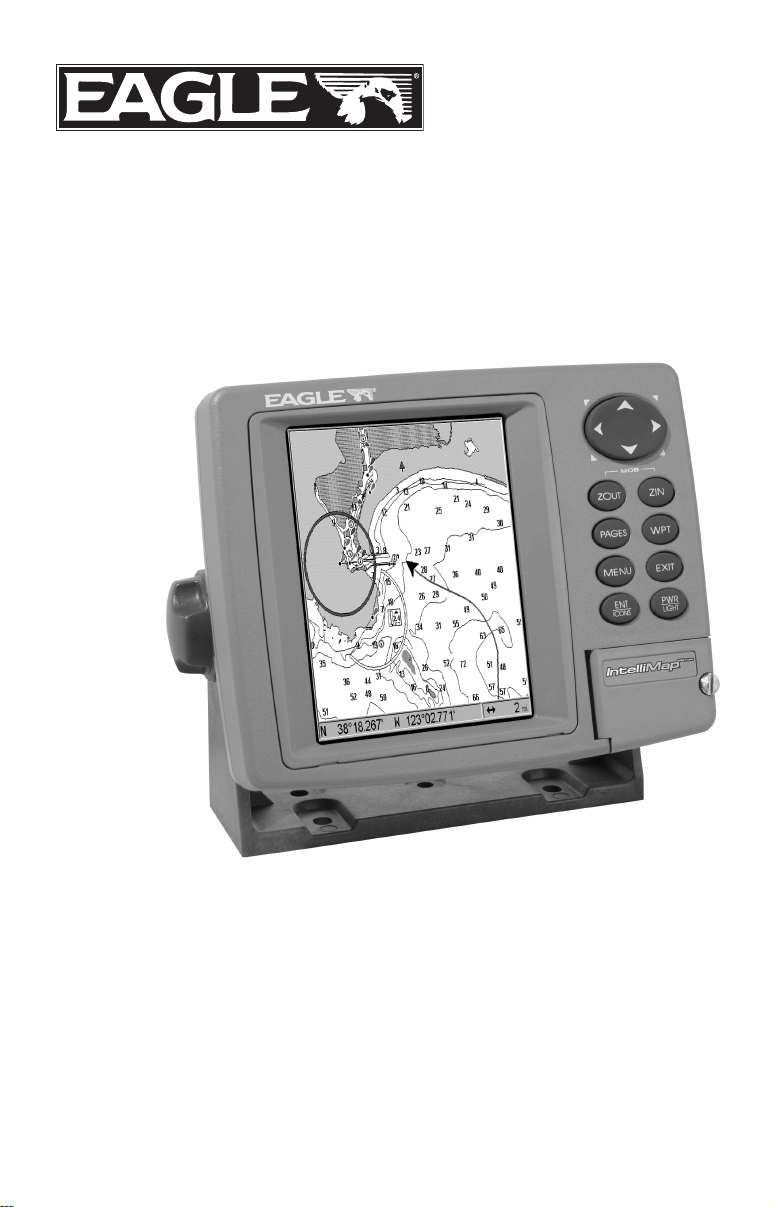
IntelliMap 642c iGPS
Mapping GPS Receiver
Installation and Operation
Instructions
Page 2

Copyright © 2005 LEI-Eagle
All rights reserved.
No part of this manual may be copied, reproduced, republished,
transmitted or distributed for any purpose, without prior written
consent of Eagle Electronics. Any unauthorized commercial
distribution of this manual is strictly prohibited.
®
Eagle
and NauticPath are trademarks of LEI. Fishing Hot Spots
registered trademark of Fishing Hot Spots Inc. LakeMaster
ProMaps are trademarks or registered trademarks of Waypoint
Technologies, Inc. Navionics
is a registered trademark of LEI. MapCreate, FreedomMaps
is a registered trademark of Navionics,
is a
and
Inc.
eXitSource Database, copyright 2001-2005 Zenrin Co.
Ltd. Exit Authority and eXitSource are trademarks of
Zenrin Co. Ltd.
Eagle Electronics may find it necessary to change or end our policies,
regulations and special offers at any time. We reserve the right to do so
without notice. All features and specifications subject to change without
notice. All screens in this manual are simulated.
For free owner's manuals and the most current information on
this product, its operation and accessories,
visit our web site:
www.eaglegps.com
Eagle Electronics
P.O. Box 669
Catoosa, OK USA 74015
Printed in USA.
Page 3

Table of Contents
Section 1: Read Me First!............................................................... 1
Capabilities and Specifications: ......................................................... 2
How GPS Works ................................................................................. 4
Introduction to GPS and WAAS......................................................... 6
How to use this manual: typographical conventions ........................ 8
Arrow Keys ...................................................................................... 8
Keyboard.......................................................................................... 8
Menu Commands ............................................................................ 8
Instructions = Menu Sequences ..................................................... 8
Section 2: Installation & Accessories....................................... 11
Preparations...................................................................................... 11
Power Connections ........................................................................... 11
NMEA Cable Connections................................................................ 14
NMEA Wiring................................................................................ 14
Mounting the Unit: Bracket or Portable ......................................... 14
MMC or SD Card Memory Card Installation.................................. 17
Other Accessories ............................................................................. 18
Section 3: Basic GPS Operations ............................................... 21
Keyboard ........................................................................................... 21
Power/lights on and off..................................................................... 22
Main Menu........................................................................................ 22
Pages ................................................................................................. 24
Satellite Status Page .................................................................... 24
Navigation Page ............................................................................ 26
Map Page ....................................................................................... 28
Background map vs. MapCreate map content............................. 30
Resize Window command ............................................................. 32
Basic GPS Quick Reference.............................................................. 34
Moving Around the Map: Zoom & Cursor Arrow Keys................... 35
Selecting Any Map Item With the Cursor ....................................... 36
Searching .......................................................................................... 36
Set a Waypoint.................................................................................. 38
Navigate To a Waypoint................................................................... 41
Set Man Overboard (MOB) Waypoint ............................................. 42
Navigate Back to MOB Waypoint.................................................... 42
Navigate to Cursor Position on Map................................................ 43
Navigate to a Point of Interest......................................................... 44
Creating and Saving a Trail............................................................. 44
Displaying a Saved Trail .................................................................. 46
Navigating Trails.............................................................................. 46
Visual Trailing .............................................................................. 47
i
Page 4

Navigate a Trail ............................................................................ 47
Navigate a Back Trail................................................................... 49
Transfer Custom Maps and GPS Data Files................................... 50
Cancel Navigation ............................................................................ 52
Section 4: Advanced GPS Operations...................................... 53
Find Distance Current Position to Another Location ..................... 53
Find Distance From Point to Point.................................................. 53
Icons .................................................................................................. 54
Create Icon on Map....................................................................... 54
Create Icon at Current Position ................................................... 54
Delete an Icon................................................................................ 54
Navigate to an Icon ....................................................................... 55
Routes................................................................................................ 55
Create and Save a Route .............................................................. 56
Delete a Route ............................................................................... 58
Edit a Route Name........................................................................ 59
Edit Route Waypoints................................................................... 59
Navigate a Route........................................................................... 59
Navigate a Route in Reverse ........................................................ 61
Trails ................................................................................................. 62
Delete a Trail................................................................................. 62
Edit a Trail Name ......................................................................... 62
Edit a Trail Color .......................................................................... 62
Edit a Trail Pattern ...................................................................... 63
Utilities ............................................................................................. 63
Alarm Clock................................................................................... 63
Sun/Moon Rise & Set Calculator.................................................. 63
Trip Calculator .............................................................................. 63
Trip Down Timer........................................................................... 63
Trip Up Timer ............................................................................... 63
Waypoints ......................................................................................... 64
Delete a Waypoint......................................................................... 64
Edit a Waypoint ............................................................................ 64
Selecting a Waypoint .................................................................... 65
Set a Waypoint by Average Position ............................................ 65
Set a Waypoint by Projecting a Position...................................... 65
Section 5: System & GPS Setup Options .................................. 67
Alarms ............................................................................................... 67
Check MMC Files and Storage Space.............................................. 68
Communications Port Configuration............................................... 68
Configure NMEA .............................................................................. 69
Coordinate System Selection ........................................................... 70
Customize Page Displays ................................................................. 71
ii
Page 5

GPS Simulator .................................................................................. 72
Initialize GPS.................................................................................... 74
Map Auto Zoom................................................................................. 74
Map Data .......................................................................................... 74
Earth Map Detail .......................................................................... 75
Pop-up Map Information .............................................................. 75
Draw Map Boundaries .................................................................. 75
Fill Water With White .................................................................. 75
Map Overlays (Range Rings; Lat/Long Grid) .............................. 75
Map Datum Selection ....................................................................... 76
Map Detail Category Drawn ............................................................ 77
Map Fix ............................................................................................. 77
Map Orientation ............................................................................... 79
NauticPath USA Marine Charts................................................... 80
Nautical Chart Notes.................................................................... 80
Port Information ........................................................................... 81
Tidal Current Information............................................................ 82
Tide Information ........................................................................... 84
Navionics
Charts............................................................................. 85
Overlay Data..................................................................................... 86
Pop-up Help ...................................................................................... 88
Reset Options.................................................................................... 89
Require WAAS .................................................................................. 89
Screen Contrast and Brightness ...................................................... 90
Set Language .................................................................................... 91
Set Local Time .................................................................................. 91
Show WAAS Alarm........................................................................... 91
Software Version Information.......................................................... 92
Sounds Menu .................................................................................... 92
Track Smoothing............................................................................... 93
Trail Options..................................................................................... 93
Delete All Trails ............................................................................ 94
Update Trail Option...................................................................... 94
Update Trail Criteria.................................................................... 94
Trail Update Rate ......................................................................... 94
Delete Trail.................................................................................... 95
New Trail....................................................................................... 95
Trail Visibility and Other Trail Options...................................... 95
Transparency .................................................................................... 96
Units of Measure .............................................................................. 97
Section 6: Searching ..................................................................... 99
Find Addresses ............................................................................... 100
Find Any Item Selected by Map Cursor ........................................ 103
iii
Page 6

Find Interstate Highway Exits ...................................................... 103
Find Map Places or Points of Interest (POI) ................................. 105
Find Streets or Intersections ......................................................... 107
Find a Street ............................................................................... 107
Find an Intersection.................................................................... 108
Find Waypoints............................................................................... 110
Section 7: Supplemental Material ........................................... 113
WARNING!
A CAREFUL NAVIGATOR NEVER RELIES ON ONLY ONE METHOD
TO OBTAIN POSITION INFORMATION.
When showing navigation data to a position (waypoint), a GPS unit will show
the shortest, most direct path to the waypoint. It provides navigation data to the
waypoint regardless of obstructions. Therefore, the prudent navigator will not
only take advantage of all available navigation tools when traveling to a waypoint, but will also visually check to make sure a clear, safe path to the waypoint
is always available.
When a GPS unit is used in a vehicle, the vehicle operator is solely responsible for operating the vehicle in a safe manner. Vehicle operators
must maintain full surveillance of all pertinent driving, boating or flying conditions at all times. An accident or collision resulting in damage
to property, personal injury or death could occur if the operator of a
GPS-equipped vehicle fails to pay full attention to travel conditions and
vehicle operation while the vehicle is in motion.
CAUTION
WARNING!
iv
Page 7

Section 1: Read Me First!
How this manual can get you out on the road, fast!
Welcome to the exciting world of digital GPS! We know you're anxious
to begin navigating, but we have a favor to ask. Before you grab the
IntelliMap
or two to explain how our manual can help you get the best performance from your compact, wide-screen, mapping GPS receiver.
First, we want to thank you for buying an Eagle GPS unit. Whether
you're a first time user or a professional fisherman, you'll discover that
your IntelliMap 642c iGPS is easy to use, yet capable of handling demanding navigation tasks. When you team your unit with our custom
mapping software MapCreate 6, you have an incredible combination.
You won't find another GPS unit with this much power and this many
features for this price!
Our goal for this book is to get you on the road fast, with a minimum of
fuss. Like you, we'd rather spend more time navigating and less time
reading the manual!
So, we designed our book so that you don't have to read the whole thing
from front to back for the information you want. At the start (or end) of
each segment, we'll tell you what content is coming up next. If it's a
concept you're already familiar with, we'll show you how and where to
skip ahead for the next important topic. We've also made it easy to look
up any tips you may need from time to time. Here's how:
The manual is organized into 7 sections. This first section is an introduction to Eagle GPS. It tells you the basics you need to know before
you can make the unit look around and tell you where you are.
Section 2 will help you install your unit. We'll show you how to get the
MultiMedia Card (MMC) correctly installed inside the unit. We'll also
tell you about some of the available accessories.
Section 3 covers Basic GPS Operation. It will show you how easy it is to
run the IntelliMap 642c, right out of the box. This section features a
one-page GPS Quick Reference. (If you've already jumped ahead
and figured out how to install the unit yourself, and you just
can't wait any longer, turn to the Quick Reference on page 34
and head for the road with your GPS unit!)
Section 3 contains short, easy-to-scan GPS lessons that follow one another in chronological order. They're all you'll need to know to find your
way on the water or in the wilderness quickly.
®
642c iGPS and begin installing it, please give us a moment
1
Page 8

After you've learned the basics (or if you already have some GPS experience), you may want to try out some of the IntelliMap 642c's many
advanced navigation features. That brings us to Section 4, Advanced
GPS Operations. This section contains the rest of the unit's GPS command functions, organized in alphabetical order.
When you come to a GPS menu command on the IntelliMap 642c's screen,
you can look it up in the manual by skimming over the table of contents,
just flipping through Section 3 or scanning through the command portion of
Section 4.
This unit is ready to use right out of the box, but you can fine tune and customize its operation with dozens of options. We describe how to use general
system options along with GPS options in Section 5, System Setup and
GPS Setup Options. Section 5 is organized in alphabetical order.
In Section 6, we go into more detail on one of the IntelliMap 642c's most
remarkable capabilities — Searching. We'll introduce a search example
in the Basic GPS Operation section, but there are so many map items
you can search for, we had to give this function its own section in the
manual! For example, did you know this unit can look up business
phone numbers, functioning as a virtual Yellow Pages? We’ll show you
how in Section 6.
Finally, in Section 7, we offer Supplemental Material, including a list of
the GPS datums used, warranties and customer service information.
Now, if you're into the fine details, glance over the next segment on
specifications to see just how much GPS power your IntelliMap 642c contains. It's important to us (and our power users), but, if you don't care
how many watts of power the unit has, or how many waypoints it can
store, skip ahead to important information on how our GPS works, on
page 4.
Capabilities and Specifications:
General
Display:............................ 5.0" (12.7 cm) diagonal color TFT LCD; pro-
grammable to viewing preference.
Resolution:...................... 640 pixel x 480 pixel resolution; 307,200 total
pixels.
Backlighting:.................. Backlit screen and keypad with multiple
lighting levels for night use.
Input power:................... 10 to 15 volts DC.
Current drain: ............... With lights on: 700 ma.
2
Page 9

Case size:......................... 5.4" H x 6.9" W x 3.4" D (13.8 x 17.6 x 8.6
cm); sealed and waterproof; suitable for
saltwater use.
MMC slots: ...................... One with waterproof door (SD card
compatible).
Recording:........................ MMC & SD cards for recording GPS trip de-
tails and displaying charts or custom maps.
Back-up memory: .......... Built-in memory stores GPS data for dec-
ades. User settings are stored when unit is
turned off.
Languages:...................... 10; menu languages selectable by user.
GPS
Receiver/antenna: ......... Internal; Built-in 12 parallel channel
GPS/WAAS .
Background map:.......... Built-in custom, detailed Eagle map. Con-
tains: enhanced detail of continental U.S.
and Hawaii. Includes more than 60,000 nav
aids and 10,000 wrecks/obstructions in
coastal and Great Lakes waters. Metro
areas, selected major streets/highways and
interstate exit services details included.
Custom mapping: .......... MapCreate
6 software optional; optional
plug and play LEI FreedomMaps offer the
same high-detail without the computer work
of MapCreate. Other plug and play mapping
options include Fishing Hot Spots
LakeMaster
Pro Maps, LEI NauticPath
marine charts and Navionics
Elite,
marine charts.
Mapping memory: ......... Up to 2 gigabytes on one MMC (or SD) card.
Position updates: .......... Every second.
Position points: ............. 1,000 waypoints; 1,000 event marker icons.
Audible alarms: ............. Arrival/off-course/anchor.
Graphic symbols for
waypoints or event
marker icons: ................. 42.
Routes:............................. 100, up to 100 waypoints per route.
Plot Trails: ...................... 10 savable; up to 10,000 points per trail.
Zoom range:.................... 40 ranges; 0.02 to 4,000 miles.
3
Page 10

NOTE:
The above memory capacities refer only to the IntelliMap 642c's onboard memory. The amount of GPS data you can record and save for
recall later is limited only by the number and size of MMC cards you
have.
NOTICE!
The storage temperature range for your IntelliMap 642c is from -4
degrees to +167 degrees Fahrenheit (-20 degrees to +75 degrees
Celsius). Extended storage in temperatures higher or lower than
specified will damage the liquid crystal display in your unit. This
type of damage is not covered by the warranty. For more informa-
tion, contact the factory's Customer Service Department; phone
numbers are listed on the last page of this manual.
How GPS Works
You'll navigate faster and easier if you understand how the IntelliMap
642c scans the sky to tell you where you are on the earth – and, where
you're going. (But if you already have a working understanding of GPS
receivers and the GPS navigation system, skip on ahead to Section 2,
Installation & Accessories on page 11. If you're new to GPS, read on.
You can later impress your friends with your new-found knowledge.)
First, think of your unit as a small but powerful computer. (But don't
worry — we made it easy to use, so you don't need to be a computer expert to find your way!) The IntelliMap 642c includes a keypad and a
screen with menus so you can tell it what to do. The screen also lets the
unit show your location on a moving map, as well as point the way to
your destination.
This gimbal-mounted IntelliMap 642c uses an internal antenna/receiver module, which makes the whole system work something
like your car radio. But instead of your favorite dance tunes, this receiver tunes in to a couple of dozen GPS satellites circling the earth. (It
will also listen in to the WAAS satellites in orbit, but more about that
in the upcoming segment introducing you to GPS and WAAS.)
Your unit listens to signals from as many satellites as it can "see" above
the horizon, eliminates the weakest signals, then computes its location
in relation to those satellites. Once the IntelliMap 642c figures its latitude and longitude, it plots that position on the moving map shown on
the screen. The whole process takes place several times a second!
The performance doesn't stop there. Stored in the permanent memory
of each unit is a basic background map of the entire world. We lock it in
here at the factory — you can't change or erase this map.
4
Page 11

The background map is suitable for many navigation chores, but for
maximum accuracy and much more detail, you need our optional mapmaking software, MapCreate 6, or one of our special plug-and-play
mapping cards. Some unit features — such as searching for businesses
and addresses — won't work without a custom MapCreate map. There
is so much detail in our background map (and even more in MapCreate)
that we'll describe their contents and differences in Section 3, Basic
GPS Operations, on page 30.
Another portion of the IntelliMap 642c's onboard memory is devoted to
recording GPS navigation information, which includes waypoints, event
marker icons, trails and routes. This lets you look back the way you came.
Think of this data storage like the hard drive memory in a computer or a
tape in a cassette tape recorder. You can save several different GPS data
files, erase 'em and record new ones, over and over again. Like any computer file, these GPS Data Files (file format *.usr) can be shared between Eagle GPS or sonar/GPS units or even personal computers.
This IntelliMap 642c has one more thing in common with a personal
computer. Just as computers have a floppy disk drive for storing and exchanging files, the unit has a slot for an MMC (MultiMedia Card) or SD
card (Secure Digital card) flash memory card. These solid-state memory
devices are about the size of a postage stamp, but can hold data ranging
from 8 MB to 1 GB in size. (Compare that to a floppy disk's 1.44 MB capacity!) This unit uses all that MMC space for two key GPS purposes.
First, you can backup your onboard GPS Data Files by copying them to
the MMC. Since the MMC is removable (like a floppy disk or a cassette
tape), you can store these GPS Data Files on a personal computer
equipped with an MMC card reader. (Or store them on a pocketful of
MMCs, if you don't have a computer.) Our MapCreate mapping software
can save, edit or create its own GPS Data Files, which can be copied to the
MMC and then loaded from the MMC into the unit's memory. (NOTE: No
matter where they come from, GPS Data Files must be loaded from the
MMC into memory before the IntelliMap 642c can use them.)
The other key GPS use for MMCs is storage of special high-detail, custom maps, which you can produce on your computer with our MapCreate software. These MapCreate custom maps contain much greater detail than the basic background map. These Custom Map Files (file
format *.lcm) can also be shared between Eagle GPS or sonar/GPS
units and personal computers.
This unit automatically reads Custom Map Files directly from the
MMC or SD card. To use a custom map, all you need to do is slide an
MMC containing a map into the IntelliMap 642c.
5
Page 12
Introduction to GPS and WAAS
Well, now you know the basics of how the unit does its work. You might
be ready to jump ahead to Section 2, Installation & Accessories, on page
11, so you can mount your IntelliMap 642c and plug in the power. Or
you might want to see how our text formatting makes the manual tutorials easy to skim. If that's the case, move on to "How to Use This Manual" on page 8. But, if you want to understand the current state of satellite navigation, look over this segment describing how GPS and its
new companion WAAS work together to get you where you're going.
The Global Positioning System (GPS) was launched July 17, 1995 by
the United States Department of Defense. It was designed as a 24hour-a-day, 365-days-a-year, all weather global navigation system for
the armed forces of the U.S. and its allies. Civilian use was also available at first, but it was less accurate because the military scrambled
the signal somewhat, using a process called Selective Availability (SA).
GPS proved so useful for civilian navigation that the federal government discontinued SA on May 2, 2000, after the military developed
other methods to deny GPS service to enemy forces. Reliable accuracy
for civilian users jumped from 100 meters (330 feet) under SA to the
present level of 10 to 20 meters (about 30 to 60 feet.)
Twenty-four satellites orbit 10,900 nautical miles above the Earth, passing
overhead twice daily. a series of ground stations (with precisely surveyed
locations) controls the satellites and monitors their exact locations in the
sky. Each satellite broadcasts a low-power signal that identifies the satellite and its position above the earth. Three of these satellites are spares,
unused until needed. The rest virtually guarantee that at least four satellites are in view nearly anywhere on Earth at all times.
A minimum of three satellites are required to determine a 2D fix.
6
Page 13

The system requires signal reception from three satellites in order to
determine a position. This is called a 2D fix. It takes four satellites to
determine both position and elevation (your height above sea level —
also called altitude). This is called a 3D fix.
Remember, the unit must have a clear view of the satellites in order to
receive their signals. Unlike radio or television signals, GPS works at
very high frequencies. These signals can be easily blocked by trees,
buildings, an automobile roof, even your body.
Like most GPS receivers, this unit doesn’t have a compass or any other
navigation aid built inside. It relies solely on the signals from the satellites to calculate a position. Speed, direction of travel, and distance
are all calculated from position information. Therefore, in order for the
IntelliMap 642c to determine direction of travel, you must be moving
and the faster, the better. This is not to say that it won’t work at
walking or trolling speeds — it will. There will simply be more "wandering" of the data shown on the display.
GPS alone is plenty accurate for route navigation, but the U.S. Federal
Aviation Administration has special aircraft navigation needs that go
beyond basic GPS. Consequently, the FAA has developed a program to
boost GPS performance with its Wide Area Augmentation System
(WAAS). The FAA commissioned the system on July 11, 2003.
WAAS is designed to increase GPS accuracy to within 7.6 meters vertically and horizontally, but according to the FAA, it consistently comes
within 1-2 meters horizontally and 2-3 meters vertically. It does this by
broadcasting correction signals on GPS frequencies. Your unit automatically receives both GPS and WAAS signals.
There are, however, some fringe areas of the U.S., including parts of
Alaska, that do not yet receive robust WAAS coverage. Continued
WAAS development is planned to extend WAAS coverage in the years
to come.
WAAS boosts the accuracy of land GPS navigation, but the system is
designed for aircraft. The satellites are in a fixed orbit around the
Equator, so they appear very low in the sky to someone on the ground
in North America. Aircraft and vessels on open water can get consistently good WAAS reception, but terrain, foliage or even large manmade structures can sometimes block the WAAS signal from ground
receivers.
You'll find that using your GPS receiver is both easy and amazingly
accurate. It’s easily the most accurate method of electronic navigation
available to the general public today.
7
Page 14

Remember that this receiver is only a tool. Always have another
method of navigation available, such as a map or chart and a compass.
Also remember that this unit will always show navigation information
in the shortest line from your present position to a waypoint, regardless
of terrain! It only calculates position, it can’t know what’s between you
and your destination, for example. It’s up to you to safely navigate
around obstacles, no matter how you’re using this product.
How to use this manual: typographical conventions
Many instructions are listed as numbered steps. The keypad and arrow
"keystrokes" appear as boldface type. So, if you're in a real hurry (or
just need a reminder), you can skim the instructions and pick out what
menu command to use by finding the boldface command text. The following paragraphs explain how to interpret the text formatting for
those commands and other instructions:
Arrow Keys
The arrow keys control the movement of dotted cross-hair lines on your
mapping screen called the cursor. The arrow keys help you move
around the menus so you can execute different commands. They are
represented by symbols like these, which denote the down arrow key,
the up arrow, the left arrow and the right arrow: ↓ ↑ ← →.
Keyboard
The other keys perform a variety of functions. When the text refers to a
key to press, the key is shown in bold, sans serif type. For example, the
"Enter/Icons" key is shown as
MENU.
Menu Commands
a menu command or a menu option will appear in small capital letters,
in a bold sans serif type like this:
you are to select this command or option from a menu or take an action
of some kind with the menu item. Text that you may need to enter or
file names you need to select are show in italic type, such as trail name.
Instructions = Menu Sequences
Most functions you perform with this unit are described as a sequence
of key strokes and selecting menu commands. We've written them in a
condensed manner for quick and easy reading.
For example, instructions for navigating a trail would look like this:
1. From the Map Page, press
2. Press ↓ to Trail 1|
ENT|→|↓ to NAVIGATE|ENT.
3. You are asked to wait while it converts the trail into a route.
ENT and the "Menu" key is shown as
ROUTE PLANNING. These indicate that
MENU|MENU|↓ to MY TRAILS|ENT.
8
Page 15

4. The wait message disappears and the IntelliMap 642c begins showing navigation information along the trail. Now, begin moving and follow your IntelliMap 642c.
Translated into complete English, step 1 above would mean: "Start on
the Map Page. Press the Menu key twice. Next, repeatedly press (or
press and hold) the down arrow key to scroll down the menu and select
(highlight) the My Trails menu command. Finally, press the Enter key."
Step 2 would mean: "Press the down arrow key repeatedly to scroll to
the trail named Trail 1, and press Enter. Next, press the right arrow
key and then the down arrow key to highlight the Navigate command,
then press Enter."
9
Page 16

Notes
10
Page 17

Section 2:
Installation & Accessories
Preparations
You can install the GPS system in some other order if you prefer, but
we recommend this installation sequence:
Caution:
You should read over this entire installation section before drilling any holes in your vehicle or vessel!
1. Determine the approximate location for the GPS unit, so you can
plan how and where to route the power cable. This will help you make
sure you have enough cable length for the desired configuration.
2. Determine the location of your battery or other power connection,
along with the power cable route.
3. Install the power cable and route it to the GPS unit.
4. Mount the GPS unit.
The IntelliMap 642c uses an internal antenna to achieve a GPS
lock. In order to get a strong signal, you need to select a mounting location that has a clear, unobstructed view of the sky.
NOTE:
The IntelliMap 642c is designed for open-cockpit boats, but the unit
will probably work in an automobile or a closed-cockpit boat if it's
mounted with a clear view through the windshield or other windows. This probably will not work if you have a cab-over design
pickup truck camper or motor home, or a boat cabin with limited
visibility. Remember: for optimum operation, this unit should be
mounted in the open with nothing obstructing its view of the sky.
Power Connections
The IntelliMap 642c works from a 12-volt battery system. For the best
results, attach the power cable directly to the battery. You can attach
the power cable to an accessory or power bus, but you might have
problems with electrical interference. Therefore, it's safer to go ahead
and attach the power cable directly to the battery.
CAUTION:
When using the unit in a saltwater environment, we strongly recommend that you shut off the power supply to the power cable when
the unit is not in use. When the unit is turned off but still connected
to a power supply, electrolysis can occur in the power cable plug.
11
Page 18
This may result in corrosion of the plug body along with the electri-
3 amp fuse
cal contacts in the cable and the unit's power socket.
In saltwater environments we recommend you connect the power
cable to the auxiliary power switch included in most boat designs.
If that results in electrical interference, or if such a switch is not
available, we recommend connecting direct to the battery and installing an inline switch. This will let you shut off power to the
power cable when the unit is not in use. When you are not using
the unit, you should always shut off power to the power cable, especially when the power cable is disconnected from the unit.
If possible, keep the power cable away from other boat wiring, especially the engine's wires. This will provide the best isolation from electrical noise. If the cable is not long enough, splice #18 gauge wire onto
it. The power cable has two wires, red and black. Red is the positive
lead, black is negative or ground. Make sure to attach the in-line fuse
holder to the red lead as close to the power source as possible.
For example, if you have to extend the power cable to the battery or
power buss, attach one end of the fuse holder directly to the battery or
power buss. This will protect both the unit and the power cable in the
event of a short. It uses a 3-amp fuse.
To unit
Black wire
Power connections for the IntelliMap 642c GPS unit.
Optional power off switch for
saltwater installations
Red wire with
12 volt
battery
WARNING:
This product must be independently fused with the enclosed 3-amp fuse (or equivalent), even if you connect to
a fused accessory or power buss.
If a malfunction happens inside the unit, extensive damage can occur if the enclosed fuse is not used. As with all
electrical devices, this unit could be damaged to a point
that it is not repairable and could even cause harm to the
user when not properly fused.
12
Page 19
CAUTION:
Failure to use the enclosed 3-amp fuse will void your warranty! For
a replacement, use a type 3AG 3-amp fuse.
This unit has reverse polarity protection. No damage will occur if the
power wires are reversed. However, the unit will not work until the
wires are attached correctly.
Rear view of unit
Power Connector
NMEA 0183
Com Port
Power cable
Com port
data wires
(three)
3-amp fuse
12-volt battery
Cable connections.
13
Page 20
NMEA Cable Connections
Yellow (Transmit)
NMEA is a standard communications format for marine electronic
equipment. For example, an autopilot can connect to the NMEA interface on the IntelliMap 642c and receive positioning information. The
IntelliMap 642c can exchange information with any device that transmits or receives NMEA 0183 data, however, a communications cable is
not available for the unit at this time. If you need to create a NMEA
0183 connection, consult customer service. Service contact information
is located in the back of this manual.
See the diagram on the preceding page for general wiring connections.
Read your other product’s owner’s manual for more wiring information.
NMEA Wiring
To exchange NMEA data, the IntelliMap 642c has one NMEA 0183 version 2.0 communication port. Com port one (Com-1) can be used to receive NMEA format GPS data. The com port can also transmit NMEA
format GPS data to another device.
A data cable should contain three wires. Com-1 uses the yellow wire to
transmit, the orange wire to receive and the shield wire for signal
ground.
Orange (Receive) NMEA Transmit
Com-1 to
IntelliMap
Shield (Ground)
Ground
To Other
GPS Receiver
Com-1 wiring to receive NMEA position information
from some other GPS receiver.
NMEA Receive
Com-1 to
IntelliMap
Com-1 wiring to transmit NMEA position information
Shield (Ground)
to another NMEA-compatible device.
Ground
Mounting the Unit: Bracket or Portable
You can install the IntelliMap 642c on the top of a dash with the supplied gimbal bracket. It can also be mounted on a portable power supply.
If you use the supplied bracket, you may be interested in an optional
R-A-M
to a swivel mount. R-A-M offers permanent mounts and temporary mounts
suitable for many vehicle types. See your Eagle dealer or visit the LEI web
site (www.lei-extras.com) for the latest options; accessory ordering infor-
bracket mounting system. This converts the unit's gimbal bracket
14
To Other
Device
Page 21
mation is on the inside back cover of this manual. For a complete look at
the many mounting options, visit the RAM web site at www.rammount.com.
Optional R-A-M mounting system.
Bracket Installation
Mount the IntelliMap 642c in any convenient location, provided there is
clearance behind the unit when it's tilted for the best viewing angle. This
must be a location with a clear view of the sky, so the internal
GPS antenna can lock-on to the satellite signals. You should also
make sure there is enough room behind the IntelliMap 642c to attach the
power cable. (a drawing on the next page shows the dimensions of a gimbal-mounted IntelliMap 642c.)
Holes in the bracket's base allow wood screw or through-bolt mounting.
You may need to place a piece of plywood on the back side of thin fiberglass panels to reinforce the panel and secure the mounting hardware.
Front
Install the gimbal bracket. Orient the bracket so the arms slope
toward the front of your unit.
Drill a 1-inch (25.4 mm) hole in the dash for the power cable. The best
location for this hole is immediately under the gimbal bracket location.
This way, the bracket can be installed so that it covers the hole, holds
the cable in position and results in a neat installation.
15
Page 22
Some customers, however, prefer to mount the bracket to the side of the
cable hole — it's a matter of personal preference.
72.9
23.4
[0.92]
173.9
[6.85]
[2.87]
137.9
[5.43]
Millimeter
[Inch]
Front view (left) and side view (right) showing dimensions of the
IntelliMap 642c when mounted on gimbal bracket.
157.9
[6.22]
56.9
[2.24]
After drilling the hole, pass the power cable's bare-wire end down
though the hole from the top.
If you wish, you can fill in the hole around the cable with a good marine
caulking compound. (Some marine dealers stock cable hole covers to conceal the opening.) No matter what type of installation you prefer, be sure
to leave enough slack in the cable to allow tilting or swiveling the IntelliMap 642c. If you choose to fill in the hole, be sure to position the cable
against the rear edge of the hole as you apply the fill material.
Before positioning the bracket, be sure to hold the cable against the
rear edge of the hole. Then, slide the bracket over the hole and butt the
rear of the bracket base firmly against the cable, thus pinning it in
place against the side of the hole. Finally, fasten the bracket to the
dash. Attach the unit to the gimbal bracket using the supplied gimbal
knobs and washers.
Portable Installation
Like many Eagle products, the IntelliMap 642c is capable of portable
operation by using an optional portable power pack (PPP). The power
16
Page 23
pack expands the uses for your GPS unit. The PPP makes it easy to
transfer your unit from a boat to a car, recreational vehicle, airplane or
other vehicle without drilling and mounting a second bracket. You can
use your unit in your own car or boat, then take it along when riding in
a friend's vehicle that's not equipped with GPS.
Most LEI portable power packs can be used with eight "D" cell alkaline
batteries. Some use an optional sealed, rechargeable battery. For information on the PPP for your unit, see the accessory ordering information inside the back cover of this manual.
"D" cell battery
Installing batteries in a typical portal power pack.
MMC or SD Card Memory Card Installation
Your IntelliMap 642c uses a MultiMedia Card to store information,
such as custom maps, waypoints, trails and other GPS data. The unit
can also use Secure Digital Cards (SD card) to store data.
NOTE:
Throughout this manual, we will use the term MMC, but just remember that your unit can use an MMC or SD card to store data.
Both of these solid-state flash memory devices are about the size of a
postage stamp. An SD card is slightly thicker than an MMC. As this
manual went to press, MMCs and SD cards were available in various
storage capacities up to 2 gigabytes.
17
Page 24
Additional MMC cards are available from LEI Extras; see ordering information inside the back cover of this manual. MMCs and SD cards
are also available at many camera and consumer electronics stores.
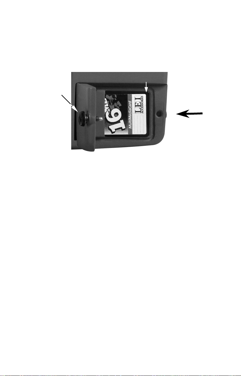
The MMC slot is located in a compartment on the front of the case. The
compartment door is located at the lower right corner. The following
figure shows a close-up with the door opened.
MMC groove for card removal
Thumb
screw
Memory card compartment with a 16 MB MMC card installed.
Insert card face up,
this way
To remove an MMC
1. Open the card compartment door by unscrewing the thumb screw.
The screw should only be finger tight. If it was over-tightened, use a
thumbnail, a coin or a screwdriver to open the door.
2. Just press a finger against the label of the MMC and drag it from the
slot.
3. Close the compartment door and fasten the thumb screw finger tight.
To add an MMC or SD Card
1. Open the card compartment door.
2. Grasp the bottom of the MMC and push the top of the card into the
slot. Once the card is started, use your fingernails to slide it the rest of
the way to the left, until it is firmly seated in the slot.
3. Close the compartment door and fasten the thumb screw finger tight.
Other Accessories
Other accessories include MMC cards, MMC card readers and MapCreate™ 6 custom mapping software for your computer. MMC card readers
are available in USB and parallel port versions.
If these accessories are not available from your dealer, see the accessory ordering information on the inside back cover of this manual.
18
Page 25
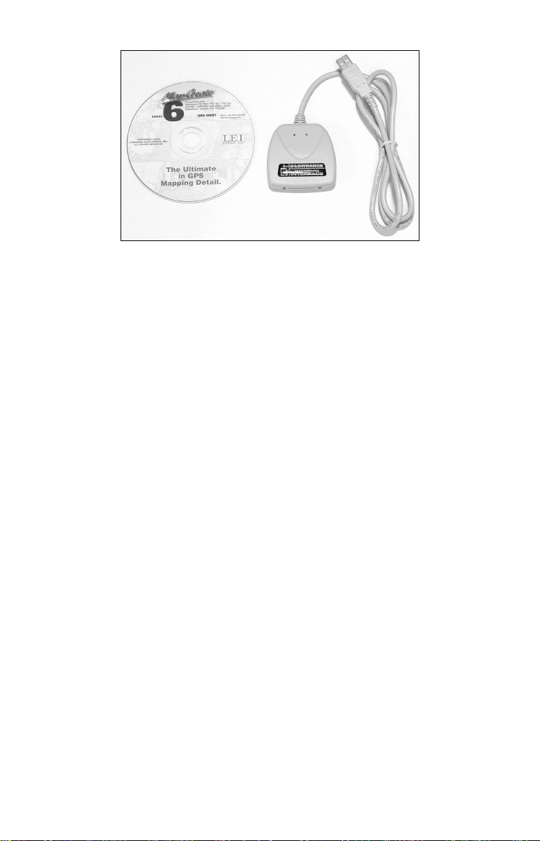
MapCreate™ 6 CD-ROM (left) MMC card reader for USB ports (right).
Now that you have your IntelliMap 642c installed, move on to Section
3, Basic GPS Operations. There, we'll present a series of step-by-step
tutorials to teach you the basics of GPS navigation.
19
Page 26

Notes
20
Page 27
Section 3: Basic GPS Operations
2
This section addresses the unit's most basic GPS operations. The tutorials presented in Sec. 3 follow a chronological order. Sec. 4, Advanced
GPS Operations, will discuss other more advanced functions and utilities. Material in Sec. 4 is arranged in alphabetical order.
Before you turn on the unit and find where you are, it's a good idea to
learn about the different keys, the three Page screens and how they all
work together. BUT, if you just can't wait to get outside, turn to the
one-page Quick Reference on page 34.
Keyboard
4
8
3
5
MMC slot access door
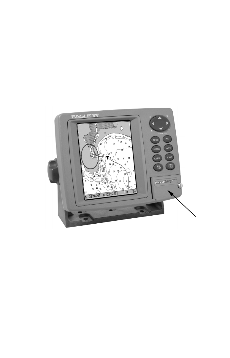
IntelliMap 642c GPS unit view showing the Map Page.
9
7
6
1
1. PWR/LIGHT – The PWR key turns the unit on and off and activates
the backlight.
2. PAGES – Pressing the Pages key and the ← → arrow keys switches
the unit between the four different page screens: Satellite Status Page,
Navigation Page and Map Page.
3. MENU – Press the Menu key to show menus and submenus. This
also accesses search functions for streets, intersections, addresses and
highway exits.
21
Page 28

4. ARROW KEYS – These keys are used to navigate through menus,
make menu selections and move around the map.
5. ENT/ICONS – The Enter key allows you to save data, accept values
and execute menu commands. It is also used to create event marker
icons.
6. EXIT – The Exit key lets you return to the previous screen, clear
data or close a menu.
7. WPT – The Waypoint key is used to save and recall waypoints,
search for waypoints and access the waypoint list. It also launches
Point-of-Interest (POI) search menus and is involved in some navigation functions.
8. ZOUT – The Zoom Out key lets you zoom out the screen. On the Map
Page, it lets you see a larger geographic area with less detail.
9. ZIN – The Zoom In key lets you zoom in the screen. On the Map
Page, it lets you see greater detail in a smaller geographic area.
Power/lights on and off
To turn on the unit, press PWR. As the unit powers up, the Map Page is
displayed first. To switch to another page, press
Name|
EXIT.
To turn on the backlight, press PWR again. The unit has three backlight
levels. Repeatedly pressing
PWR will cycle through the backlight set-
tings and turn off the backlight.
Turn off the unit by pressing and holding the
PAGES|← → to Page
PWR key for 3 seconds.
Main Menu
The unit has a Main Menu, which contains some function commands and
some setup option commands. The tutorial lessons in this section will
deal only with functions, the basic commands that make the unit do
something. The GPS will work fine for these lessons right out of the box
with the factory default settings. But, if you want to learn about the
various options, see Sec. 5, System Setup and GPS Setup Options.
You can access the Main Menu from any of the three Page screens by
pressing
display, press
MENU|MENU. To clear the menu screen and return to the page
EXIT.
22
Page 29
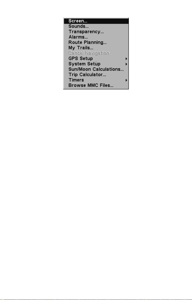
Main Menu.
The Main Menu commands and their functions are:
Screen: changes the contrast or brightness of the display screen.
Sounds: enables or disables the sounds for key strokes and alarms and
sets the alarm style.
Transparency: adjusts the level of transparency for menus.
Alarms: turns GPS alarms on or off and changes alarm thresholds.
Route Planning: used to plan, view or navigate a route.
My Trails: shows, creates and deletes plot trails. Also used to navigate
or backtrack a trail.
Cancel Navigation: turns off the various navigation commands. Used
to stop navigating after you have reached your destination.
GPS Setup: sets various GPS receiver options.
System Setup: sets general configuration options.
Sun/Moon Calculations: finds the rising and setting time of the sun
and the moon.
Trip Calculator: shows trip status and statistics.
Timers: controls the up timer, down timer and alarm clock settings.
Browse MMC Files: allows you to view the installed MMC card and
the files it contains.
23
Page 30
Pages
The unit has three Page displays: Satellite Status Page, Navigation
Page and Map Page. They are accessed by pressing the
then using ← → to select a Page. (Clear the Pages Menu by pressing
EXIT.)
Pages Menu showing some Map display options.
Satellite Status Page
The Satellite Status Page, shown in the following images, provides detailed information on the status of the unit's satellite lock-on and position acquisition. To get to the Satellite Status Page: Press the
key, then use ← → to select STATUS. (Clear the Pages Menu by pressing
EXIT.)
PAGES key,
PAGES
No matter what Page you are on, a flashing current position indicator/question mark symbol and flashing GPS data displays indicate that
satellite lock has been lost and there is no position confirmed. The Satellite Status Page shows you the quality and accuracy of the current
satellite lock-on and position calculation.
WARNING:
Do not begin navigating with this unit until the numbers
have stopped flashing!
24
Page 31

Satellite Status Page. The first figure (left) indicates unit has not locked
on to any satellites and does not have a fix on its position. The second
figure (right) shows satellite lock-on with a 3D position acquired (lati-
tude, longitude and altitude), and WAAS reception.
This screen shows a graphical view of the satellites that are in view. Each
satellite is shown on the circular chart relative to your position. The point in
the center of the chart is directly overhead. The small inner ring represents
45° above the horizon and the large ring represents the horizon. North is at
the top of the screen. You can use this to see which satellites are obstructed
by obstacles in your immediate area if the unit is facing north.
The GPS receiver is tracking satellites that are in bold type. The receiver hasn't locked onto a satellite if the number is grayed out, therefore it isn't being used to solve the position.
Beneath the circular graph are the bar graphs, one for each satellite in
view. Since the unit has twelve channels, it can dedicate one channel
per visible satellite. The taller the bar on the graph, the better the unit
is receiving the signals from the satellite.
NOTE:
One of the data display options for the Satellite Status page is "Position Error" (horizontal position error), which can appear in one of
the page's data boxes. Position Error will show you the expected error from a benchmark location. In other words, if the Position Error
box shows 50 feet, then the position shown by the unit is estimated
to be within 50 feet of the actual location.
This also gives you an indicator of the fix quality the unit currently
has. The smaller the position error number, the better (and more accurate) the fix is. If the position error flashes dashes, then the unit
hasn't locked onto the satellites, and the number shown isn't valid.
(For details, see Customize Page Displays, on page 71.)
25
Page 32

The Satellite Status Page has its own menu, which is used for setting
various options. (Options and setup are discussed in Sec. 5). To access
the Satellite Status Page Menu, from the Status Page, press
MENU.
Navigation Page
This screen has a compass rose that not only shows your direction of
travel, but also the direction to a recalled waypoint. To get to the Navigation Page, press
PAGES|← → to NAVIGATION|EXIT.
The navigation screen looks like the one below when you're not navigating to a waypoint or following a route or trail. Your position is
shown by an arrow in the center of the screen. Your trail history, or
path you've just taken, is depicted by the line extending from the arrow.
The arrow pointing down at the top of the compass rose indicates the current track (direction of travel) you are taking.
Track or compass heading indicator, showing direction of travel
Compass
rose
Trail line
Navigation
information
displays in
customizable
data boxes
Present
position
arrow
Traveling north and recording a trail on the Navigation page. The
page looks like this when the unit is not navigating to a waypoint, fol-
lowing a route or backtracking a trail.
When navigating to a waypoint, the Navigation screen looks like the
following figure. Your ground speed, track, distance and bearing to
waypoint, and course are all shown digitally on this screen.
NOTE:
Remember, when the Speed, Track and Position information displays are flashing, satellite lock has not been achieved and no position fix has been determined. A question mark will also flash on the
present position arrow in the center of the compass rose.
26
Page 33

Speed (ground speed) is the velocity you are making over the ground. (If
arrow
you wish, you can customize the Speed data box to display Closing
Speed instead. Closing Speed is also known as velocity made good. It's
the speed that you're making toward the waypoint. For instructions,
see the Customize Page Displays entry in Sec. 5.)
Track is the heading, or the current direction you are actually traveling. Bearing is the direction of a line-of-sight from your present position
to the destination. No matter what direction you are steering, the
Bearing window shows the compass direction straight to the destination from your location at the moment. Distance shows how far it is to
the waypoint you're navigating toward.
The Off Course window shows the current cross track error. This shows
the distance you are off-course to the side of the desired course line. The
course line is an imaginary line drawn from your position when you
started navigating to the destination waypoint. The course line is shown on
the Navigation Page screen (and the Map Page screen) as a dotted line.
Heading arrow
Red course line
Magenta
trail line
Navigation
information
displays
in data boxes
Navigation Page going to a waypoint while creating a new trail.
Bearing
Cross track
error range
(off course
indicator)
Destination
name
The cross track error range is shown on the compass rose as a wide,
white, corridor enclosing the course line. The outer edges of this white
corridor represent lines that show the current cross track error range.
The default for the cross track error range is 0.20 miles.
For example, if the present position symbol touches the right cross
track error line, then you are 0.20 miles to the right of the desired
27
Page 34

course. You need to steer left to return to the desired course. You can
use the
ZIN or ZOUT keys to change the cross track error range.
A circular symbol depicting your destination (waypoint) appears on the
screen as you approach the waypoint, as shown on the screen in the
preceding figure.
Travel Time is the time that it will take to reach your destination at
your present closing speed. (You can also customize the time data box
to show Arrival Time instead. Arrival Time is the local time it will be
when you arrive at the destination, based upon your present closing
speed and track.)
In the preceding example figure, the driver is headed northwest (a 345º
track) toward a waypoint 346º (bearing) away. The cross track error
range (white corridor) is 0.15 miles either side of the course. The driver
is headed toward trail waypoint 1, which is 0.3 miles away. The vehicle
is 234 feet right of the original course. Traveling at a speed of 17 mph,
the driver will arrive at the waypoint in 1 minute, 3 seconds.
The Navigation Page has its own menu, which is used for some advanced functions and for setting various options. (Options and setup
are discussed in Sec. 5). To access the Navigation Page Menu, from the
Navigation Page, press
MENU.
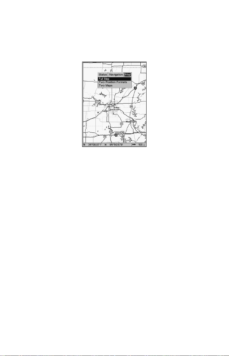
Map Page
The Map Page screens show your course and track from a "bird's-eye"
view. By default, this unit shows the map with north always at the top
of the screen. (This can be changed. See the topic Map Orientation, in
Sec. 5.) If you're navigating to a waypoint, the map also shows your
starting location, present position, course line and destination. You
don't have to navigate to a waypoint, however, to use the map.
Map Page is the default screen that appears when you turn on the unit.
To get to the Map Page from another page: Press
MAP|EXIT. When the Map Page is displayed, a screen similar to the fol-
PAGES|← → to
lowing figures appears.
The arrow in the center of the screen is your present position. It points
in the direction you're traveling. The solid line extending from the back
of the arrow is your plot trail, or path you've taken.
The map zoom range is the distance across the screen. This number
shows in the lower left corner of the screen. In the first of the following
example figures, the range is 4,000 miles from the left edge of the map
to the right edge of the map.
28
Page 35

The Zoom In and Zoom Out keys zoom the map to enlarge or reduce its
coverage area and the amount of mapping detail shown. There are 40
available map zoom ranges, from 0.02 miles to 4,000 miles.
Map Page opening screen (left). Map page zoomed to 100 miles (cen-
ter). Map zoomed to 10 miles (right). Over Zoomed means you have
reached the detail limits in an area covered only by the basic background map. Zooming in any closer will reveal no more map detail.
If you're using only the factory-loaded background map, the maximum
zoom range for showing additional map detail is 15 miles. You can continue to zoom in closer, but the map will simply be enlarged without
revealing more map content (except for a few major city streets.) Load
your own high-detail custom map made with MapCreate (or a pre-made
FreedomMap from LEI), and you can zoom in to 0.02 miles with massive amounts of accurate map detail.
Map Pages with high-detail MapCreate map of urban area loaded on
the MMC. Arterial streets are visible at the 4-mile zoom range (left).
Numerous dots representing Points of Interest are visible at the 2-mile
range (center), along with minor streets. At the 0.4-mile zoom (right),
you can see an interstate highway with an exit, major and minor
streets as well as Point of Interest icons.
29
Page 36

Background map vs. MapCreate map content
The background map includes: low-detail maps of the whole world (containing cities, major lakes, major rivers, political boundaries); and medium-detail maps of the United States.
The medium-detail U.S. maps contain: all incorporated cities; shaded
metropolitan areas; county boundaries; shaded public lands (such as
national forests and parks); some major city streets; Interstate, U.S.
and state highways; Interstate highway exits and exit services information; large- and medium-sized lakes and streams; and more than 60,000
navigation aids and 10,000 wrecks and obstructions in U.S. coastal and
Great Lakes waters
MapCreate custom maps include massive amounts of information not
found in the background map. MapCreate maps contain the searchable
Points of Interest database, all the minor roads and streets, all the
landmark features (such as summits, schools, radio towers, etc.); more
rivers, streams, smaller lakes and ponds and their names.
What's more important is the large scale map detail that allows your
GPS unit to show a higher level of position accuracy. For example, the
background map would show you the general outline and approximate
shape of a coastline or water body, but the higher detail in MapCreate
shows the shoreline completely and accurately (finer detail). Many
smaller islands would not be included in the background map, but are,
of course, in MapCreate.
NOTE:
Available through LEI Extras (look inside back cover for accessory
ordering information), FreedomMaps are pre-made maps that contain all of the same information available in a custom MapCreate
map, without any of the work of preparation.
30
Page 37

Minor
Streets
Interstate
Major Street
Cursor line
POI
Marker
School
POI
POI
Pop-up
Restaurant
POI
Zoom Range
When the map is zoomed out far enough, most POIs appear as square
dots (left). As you zoom in closer, the symbols become readable icons.
In the 0.2-mile zoom example (right), the cursor has selected the Cupps
Café POI, which triggers a pop-up box with the POI name. This pop-up
box works on POIs at any zoom range.
Position, distance
and bearing data
Tip:
In some urban areas, businesses are so close to one another that
their POI icons crowd each other on the screen. You can reduce
screen clutter and make streets and other map features easier to
see by simply turning off the display of POIs you're not watching
for. (To see how, check the text on Map Detail Category Selection,
page 77. It shows how to use the Map Categories Drawn menu to
turn individual POI displays off and on.) Even though their display
is turned off, you can still search for POIs and their icons will popup when your unit finds them for you.
The Map Page has its own menu, which is used for several functions
and for setting various options. To access the Map Page Menu, from the
Map Page, press
The Pages Menu also offers several map display options under the Map
Page category. To access them, press
tion|
EXIT.
MENU.
PAGES|← → to MAP|↓ to Op-
31
Page 38

Two Position Formats map page option.
In pages that have two major windows (such as two maps) you can toggle back and forth between the two windows by pressing
PAGES|PAGES. Each time you switch between the windows, Active
Map will be displayed at the top of the active window.
Pages Menu with Two Map option selected (left).
Map Page with two map windows (right).
Resize Window command
Resize Window is another extremely handy feature for pages that have two
major windows. You can change the relative size of the windows, as well as
horizontal or vertical layout, to suit your viewing preference. Here's how:
1. From any two-window display, press
MENU|↓ to RESIZE WINDOW|ENT.
2. Four flashing arrows appear along the centerline dividing the two
windows. Press an arrow key perpendicular to the centerline to adjust
the window widths.
32
Page 39

Press an arrow key parallel to the centerline to switch between horizontal and vertical layout. Press
Fig. 1. Fig. 3.
EXIT to clear the four flashing arrows.
Fig. 2.
Fig. 1. Two Maps page display with four flashing arrows on the divid-
ing centerline. Fig. 2. The centerline has been moved down to enlarge
the top map, which is now zoomed in to 40 miles. Fig. 3. Pressing → has
switched the page layout from horizontal to vertical.
3. To change the window size again or revert back to the original display, just follow the steps above. (Most dual-window displays use half
the screen for each window by default.) You can also use the Reset Options command to revert to the factory default.
NOTE:
The units described by this manual are all capable of using this
command. If your unit does not have a Resize Window command on
the Map Page menu, you can update your software by visiting our
web site www.eaglegps.com or by contacting customer service.
The following page contains a 12-step quick reference for the most basic
GPS operations. If you don't want to carry the manual with you as you
practice with the unit, you might consider photocopying this quick reference page and tucking it into your pocket.
33
Page 40

Basic GPS Quick Reference
Start outdoors, with a clear view of the open sky. As you practice, try
navigating to a location at least a few blocks away. While you're learning,
navigation in too small an area will constantly trigger arrival alarms.
1. Connect the unit to electric power and the antenna module. Make sure
the MMC is in. (See complete installation details beginning on page 11.)
2. To turn on the unit, press and release
3. Opening screen displays map of North America at 4,000 mile zoom
range. Rotate through the three main Page screens (Map Page, Satellite Status Page and Navigation Page) by pressing
lect Page Name|
EXIT. Switch Pages to display Satellite Status Page.
4. Wait while unit locates satellites and calculates current position. Process
is visible on Satellite Page. This takes about a minutes or less under clear
sky conditions (unobstructed by terrain or structures.) When position is
acquired, unit sounds a tone and displays a "position acquired" message.
The present position arrow and information shown in data boxes or as
overlay data will stop flashing.
5. With position acquired, press
PAGES key to display Map Page, which
shows a bird's eye view of the earth. You can move around the map by:
Zoom in closer to see greater detail: press
Zoom out to see more area, less detail: press
Scroll map north, south, east or west using arrow keys ↑ ↓, ← →.
To stop scrolling and return to current position on map, press
6. Set a waypoint (Wpt 001) at your current position so you can navigate
back here: press
WPT|WPT. Waypoint symbol and "001" appears.
7. Zoom/scroll map to find a nearby object or location to go to. Use arrow keys to center cursor cross-hair over the map object or location.
8. Navigate to the selected destination: press
course line on Map Page or compass bearing arrow on Navigation Page.
9. At destination, Arrival Alarm goes off; to clear it, press
navigation: press
MENU|MENU|↓ to CANCEL NAVIGATION|ENT|← to YES|ENT.
10. Return to Wpt 1 by Navigate To Waypoint or Backtrack Trail. To
Waypoint: press
ENT|ENT; follow navigation displays. Trail: press MENU|MENU|↓ to MY
TRAILS|ENT. Press ↓ to Trail 1|ENT|↓ → to NAVIGATE|ENT. Press ↓ → to
REVERSE |ENT|← to NAVIGATE |ENT. (If arrival alarm sounds, press EXIT.)
WPT|ENT|↓|ENT. Use ↑ or ↓ to select Wpt 001, press
Follow navigation displays.
11. Back home, Arrival Alarm goes off; press
press
MENU|MENU|↓ to CANCEL NAVIGATION|ENT|← to YES|ENT.
12. To turn off the unit, press and hold
PWR key.
PAGES|← → to se-
ZIN (zoom in key.)
ZOUT (zoom out key.)
EXIT key.
MENU|ENT|EXIT. Follow red
EXIT. Cancel
EXIT. Cancel navigation:
PWR key for three seconds.
34
Page 41

Find Your Current Position
Finding your current position is as simple as turning on the unit. Under clear sky conditions, the unit automatically searches for satellites
and calculates its position in approximately one minute or less.
NOTE:
Clear sky conditions means open sky, unobstructed by terrain,
dense foliage or structures. Clouds do not restrict GPS reception.
If for some reason satellite acquisition takes longer, you may be inside
a structure or vehicle or in terrain that is blocking signal reception. To
correct this, be sure you are positioned so that the unit has as clear a
view of the sky as possible, then turn the unit off and back on again.
Moving Around the Map: Zoom & Cursor Arrow Keys
The map is presented from a bird's eye view perspective. The current
zoom range shows in the lower left corner of the screen.
1. Press the
ZIN key (zoom in) to move in closer and see greater detail in
a smaller geographic area.
2. Press the
ZOUT key (zoom out) to move farther away and see less map
detail, but a larger geographic area.
When you are traveling, the map will automatically move as you move.
This keeps your current location roughly centered on the screen.
You can manually pan or scroll the map northward, southward, eastward or westward by using the arrow keys, which launch the cross-hair
map cursor. This allows you to look at map places other than your current position. To clear the cursor, press
EXIT, which jumps the map
back to the current position or the last known position.
Tip:
Use the cursor to determine the distance from your current position
(or last known position, when working indoors) to any map object or
location. Use the arrow keys to position the cursor over the object or
place. The distance, measured in a straight line, appears in the
popup data box. Press
EXIT to clear the cursor.
35
Page 42

Distance
measured
by cursor
Pop-up
name box
Selected
wreck
Cursor
line
The selected wreck (the Empress) to the southeast is 12.81 miles away.
Cursor
line
Selecting Any Map Item With the Cursor
1. Use the zoom keys and the arrow keys to move around the map and
find the item you wish to select.
2. Use the arrow keys and center the cursor cross-hair on the desired object. On most items, a pop-up box will give the name of the selected item.
Tip:
This unit has a Cursor Undo feature that lets you instantly return
to the previous location without scrolling. Use the cursor to scroll
across the map to some far away location or waypoint. Press
clear the cursor and jump back to your current position on the map.
When you want to take another peek at that distant place, just
press
EXIT again. You can use this trick to toggle between your cur-
rent position and your destination.
EXIT to
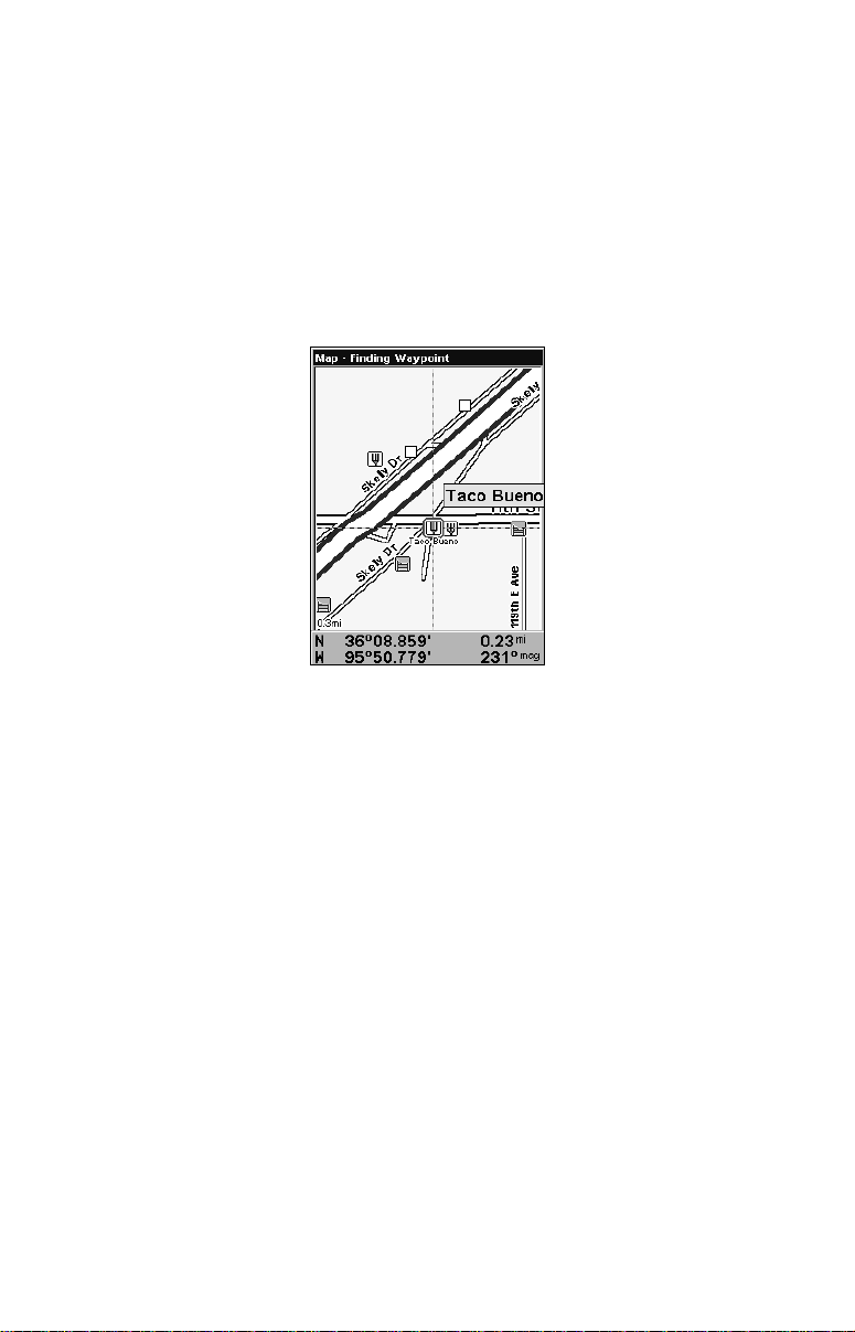
Searching
Now that you have seen how the unit can find your current location,
let's search for something else. Searching is one of the most powerful
features in the Eagle GPS product line.
In this example, we will look for the nearest fast-food restaurant. For
information on different types of searches, refer to Sec. 9, Searching.
NOTE:
This example requires the Point of Interest (POI) database included
with a high-detail MapCreate 6 custom map.
36
Page 43

1. After the unit has acquired a position, press
ESTAURANTS.
R
WPT|↓ to POI-
2. You could search the entire restaurant category, but in this example
we will narrow our search. Press → ↓ to
NEAREST|ENT.
FAST FOOD CHAINS|ENT|↓ to
3. A list of restaurants will appear with the closest at the top of the list,
and the one furthest from you at the bottom of the list. The nearest is
highlighted.
Find Waypoint Menu (left). Category Selection menu (center). List of
the nearest restaurants (right).
4. If you wish, you could scroll ↑ ↓ here to select another restaurant,
but for now we will just accept the nearest one. Press
ENT.
5. The POI information screen appears. If you wanted to navigate
there, you could press Enter, since the Go To Waypoint command is
highlighted. We only want to see it on the map, so press ↓ to
MAP|ENT.
FIND ON
POI information screen on fast food restaurant nearest this position.
Go To command highlighted (left). Find On Map highlighted (right).
37
Page 44
5. The POI information screen appears. (This is how you can use this
unit as a business phone directory!) If you wanted to navigate there,
you could by pressing Enter. The Go To waypoint command is already
highlighted. But we just want to see it on the map, so press ↓ to
MAP|ENT.
FIND ON
6. The unit's map appears, with the cursor crosshairs highlighting the
restaurant' s POI symbol. A pop-up data box shows the POI's name. A
data box at the bottom of the screen displays the location's latitude,
longitude, distance and bearing.
Finding Waypoint screen showing
the result of a restaurant search.
7. To clear the search and return to the last page displayed, press EXIT
repeatedly. Before you exited out of the Search menus, you could have
gone looking for another place.
NOTE:
Search works from mapping and POI data loaded in the unit. If you do
not have a high-detailed custom map for the area you are searching, you
may not find anything.
Set a Waypoint
A waypoint is an electronic address based on the latitude and longitude
of a position on the earth. It represents a location, spot or destination
that can be stored in memory, then recalled and used later on for navigation purposes.
You can create a waypoint at the cursor position on the map or at your
current position while navigating. You can create a waypoint at any
location by manually entering the position's latitude and longitude. You
can copy waypoints from your unit to your personal computer with
38
Page 45

MapCreate software. When you want to repeat a trip, these archived
waypoints can be reloaded into your GPS unit.
To create and save a Waypoint:
These first two techniques use the Quick Save method, the fastest and
easiest way to create a waypoint.
Create Waypoint at Current Position
While you are traveling, press WPT|WPT. The waypoint is saved and
automatically given a name with a sequential number, such as waypoint 003. The waypoint symbol and number appear on the map.
NOTE:
The Quick Save method uses the default waypoint symbol until you
edit an existing waypoint and change its symbol. (Edit Waypoint
Symbol is described in Sec. 7.) After you have changed a waypoint
symbol, the unit will remember the one you chose and use it the
next time you quick save a waypoint. To revert back to the default
symbol, edit a waypoint and choose the original symbol, or use the
Reset Options command (described in Sec. 8).
39
Page 46

Step 1. Step 2.
Step 3.
Step 4.
Sequence for setting a waypoint. Step 1: while traveling, press WPT to
call up Find Waypoint screen (seen in Step 2) and set a point. Step 3: a
message says the waypoint has been saved. Step 4: vehicle continues
on its way; number waypoint symbol is visible on map.
Create Waypoint on Map
1. Use the arrow keys to move the cursor to the place where you want
to make a waypoint.
2. Press
WPT|WPT. The waypoint is saved and automatically given a
name with a sequential number, such as waypoint 001. The waypoint
symbol and number appear on the map.
Create Waypoint by Entering a Position
1. Press WPT|↑ to MY WAYPOINTS|→ to NEW|ENT.
2. Press ↓ to
3. Press → to
ENTERED POSITION|ENT|→ to CREATE|ENT.
LATITUDE|ENT. Enter the latitude by pressing ↑ ↓ to
change the first character, then press → to the next character and repeat until the latitude is correct. Press
ENT.
40
Page 47

4. Press ↓ to
LONGITUDE|ENT. Enter the longitude by pressing ↑ ↓ to
change the first character, then press → to the next character and repeat
until the longitude is correct. Press
ENT, then EXIT|EXIT to return to the
previous page display. The waypoint is saved and automatically given a
name with a sequential number, such as waypoint 001. The waypoint
symbol and number appear on the map and in the waypoint list.
Navigate To a Waypoint
You can select any waypoint on the Map Page with the cursor, then use
the Navigate to Cursor command (we will describe how later in this
section.) You, however, can avoid scrolling the map to pick your waypoint if you use the Find Waypoint commands.
1. Press
press ↓ to
tire waypoint list — press ↓|
WPT|↑ to MY WAYPOINTS|ENT. To look up the nearest waypoint,
NEAREST|ENT. To look by name — and scroll through the en-
ENT. For this example, let's look by name.
2. If your waypoint list is a long one, you can spell out the waypoint name
in the
FIND BY NAME box. Press ↑ ↓ to change the first character, then press
→ to move the cursor to the next character and repeat until the name is
correct, then press
3. If the list is short, you can jump directly to the
pressing
ENT. Use ↑ ↓ to select the waypoint name, press ENT and the
waypoint information screen appears with the
4. To begin navigating to the waypoint, press
Course line
(red)
Off course
range, set at
0.20 mile
ENT to jump to the list below.
FIND IN LIST box by
GO TO command selected.
ENT.
Trail line
(magenta)
Destination
name
Navigating to waypoint 002 and leaving a trail.
41
Page 48

Set Man Overboard (MOB) Waypoint
One of boating's most terrifying events is having a friend or family
member fall overboard. This unit has a man overboard feature that
shows navigation data to the location where the feature was activated.
To activate it, press the
ZOUT and ZIN keys at the same time. Your posi-
tion at the time these keys are pressed is used as the man overboard
position.
Caution:
Saving a new Man Overboard waypoint will overwrite and erase
the previous Man Overboard waypoint.
Navigate Back to MOB Waypoint
Find your way back to the accident position with the Navigation Page
or Map Page. When MOB is activated, the Navigation Page automatically shows the compass rose with its bearing arrow pointing toward
the man overboard position, and the destination name says Going To
Man Overboard. The Map Page displays a Man Overboard waypoint,
represented by a human figure, and the steering arrow points where to
steer to reach that position.
Navigating to Man Overboard: Man Overboard activated message
(left). The Navigation Page is shown (center). Going to Man Overboard
position on Map Page (right).
The man overboard position is also stored in the waypoint list for future
reference. It can be edited the same as any other waypoint. This prevents the inadvertent loss of the current Man Overboard position.
To cancel navigation to MOB, press
NAVIGATION|ENT|← to YES|ENT. The unit stops showing navigation infor-
MENU|MENU|↓ to CANCEL
mation.
42
Page 49

Navigate to Cursor Position on Map
The GO TO CURSOR command navigates to the current cursor position on
the map. It is a quick way to navigate to anything you can see on the
map display.
1. Use the cursor with the zoom in and zoom out keys to move around
the map until you find a location you want to go to.
2. Center the cursor over the location to select it. See the example in
the following figure. Map items like waypoints, Points of Interest and
towns among others, can be selected and appear highlighted with a
pop-up box. Other features, such as a river or a street intersection will
not appear highlighted, but the cursor will take you to those locations
just the same.
The cursor crosshairs are centered on Oologah, Oklahoma.
3. Press MENU|ENT and the unit will begin navigating to the cursor location.
The Map Page will display a red line from your current position to the cursor position. The Navigation Page displays a compass rose showing navigation information to your destination. See the following examples.
43
Page 50

The 60-mile zoom figure (left) shows the red course line connecting the
current position to the destination. The Navigation Page (right) will also
show navigation information.
To stop navigating to the cursor, use the Cancel Navigation command.
Press
MENU|MENU|↓ to CANCEL NAVIGATION|ENT|← to YES|ENT. The unit
stops showing navigation information.
Navigate to a Point of Interest
You can use the Navigate to Cursor command for POIs in view on the
map, just use the cursor to select the POI.
The other method involves searching for POIs with the Find Waypoint
command, launched with the
WPT key. (See the searching example ear-
lier in this section or turn to Sec. 9, Searching, for more instructions.)
After you have looked up an item with the Find Waypoint command,
use ← → to make sure the
of the screen, then press
GO TO command is highlighted at the bottom
ENT. The unit begins showing navigation in-
formation to the item.
To cancel navigation, press
to
YES|ENT. The unit stops showing navigation information.
MENU|MENU|↓ to CANCEL NAVIGATION|ENT|←
Creating and Saving a Trail
A trail or plot trail, is a string of position points plotted by the unit as you
travel. It is a travel history, a record of the path you have taken. Trails
are useful for repeating a journey along the same track. They are particularly handy when you are trying to retrace your trip and go back the
way you came. On the screen, trails are represented by a solid line extending from the back of the current position arrow. The default color is
light magenta.
44
Page 51

The unit is set to automatically create and record a trail when it is
turned on. The unit will continue recording the trail until the length
reaches the maximum trail point setting. The default is 2,000 points,
but the unit can record trails 9,999 points long. When the point limit is
reached, the unit begins recording the trail over itself.
With the default auto setting, this unit creates a trail by placing a dot on
the screen every time you change directions. The methods used for creating a trail and the trail update rate can be adjusted or even turned off.
See Sec. 8 for Trail Options.
To preserve a trail from point A to point B, you must turn off the trail
by making it inactive before heading to point C or even back to point A.
When the current trail is set inactive, the unit automatically begins
recording a new trail.
To Save a Trail
1. Press
MENU|MENU|↓ to MY TRAILS|ENT.
Visible
symbol
Active
symbol
Sequence for saving a trail and beginning a new one. My Trails com-
mand (left). The Trails Menu (center). The arrow to the right of Trail 3
indicates the trail is active and the check to the left indicates the trail
is visible on the map display. The third figure (right) shows the Edit
Trail menu, with the Name command selected.
2. Press ↓ to the Active Trail Name|ENT.
3. Press ↓ → to
4. To return to the previous page, press
ACTIVE|ENT. This unchecks the Active option.
EXIT repeatedly. As you leave
the Edit Trail menu, a new trail starts with a new sequential number.
You can save and recall up to 10 different plot trails, which can be copied to your MMC for archiving or for transfer to your MapCreate software.
45
Page 52

Tip:
Another quick way to stop recording one trail and begin a new one
is to use the New Trail command. Press
TRAILS|ENT|ENT.
Caution:
You also have the option of completely turning off trail recording, under the trail Options command. If, however, the Update
Active Trail option is left turned off, it will cancel the automatic
trail creation feature.
MENU|MENU|↓ to MY
Displaying a Saved Trail
The active trail is automatically displayed on the with the default settings. You can selectively turn trail display off and on for any saved or
active trail. In the Saved Trails List, visible trails have a check mark in
front of the trail name.
To turn off trail display:
1. Press
2. Press ↓ to enter the Saved Trail list, then use ↑ ↓ to select the desired Trail Name|
3. Press ↓ → to
repeatedly. Repeat the steps above to the turn on the trail display.
MENU|MENU|↓ to MY TRAILS|ENT.
ENT.
VISIBLE|ENT. To return to the previous page, press EXIT
Navigating Trails
There are three methods for following a trail: visual trailing, navigating
a trail and backtracking a trail. Try each method to see which you prefer.
Visual trailing is the simplest method. It uses only the Map Page and
requires no menu commands at all. The technique works the same if
you are running a trail forward (from start to end) or backward (from
end to start.) Visual trailing, however, provides no navigation information during the trip, like time to your destination.
The other two methods provide a full range of navigation data and work
with both the Map Page and Navigation Page. The only difference between them is navigating a trail follows a trail forward while backtracking follows a trail in reverse.
When hiking at walking speed with a hand-held GPS, we often just use
visual back trailing because it is a bit better at following each turn on a
foot path. At faster speeds, like on the highway or on the water, the
Navigate Trail and Backtrack Trail commands are handy.
46
Page 53

Visual Trailing
1. On the Map Page, zoom (
ZIN or ZOUT) so your trail is visible.
2. Begin moving and watch the Map Page. Walk or steer so your current position arrow traces along the trail you have just made.
Tip:
Generally, when using this method, the smaller the zoom range, the
more accurately you will be able to steer along the trail.
Navigate a Trail
The following figures illustrate the menu sequence for navigating a trail.
1. Press
2. Press ↓ to enter the Saved Trail list, then use ↑ ↓ to select the desired Trail Name|
3. Press ↓ → to
The unit begins showing navigation information along the trail.
NOTE:
5. Now, begin moving and let your unit guide you.
6. When you reach your destination, be sure to cancel your navigation.
Press
will appear. Press ←|
MENU|MENU|↓ to MY TRAILS|ENT.
ENT.
NAVIGATE|ENT. Press ↓|NAVIGATE| ENT.
If you are already located at or near the beginning of your trail, the
arrival alarm will go off as soon as you hit Enter. Just press
EXIT to
clear the alarm and proceed.
MENU|MENU|↓ to CANCEL NAVIGATION|ENT. A confirmation message
ENT.
47
Page 54

Figure 1.
Figure 3.
Figure 2.
Figure 4.
Navigate a trail menu sequence: Fig. 1, My Trails command. Fig. 2,
Trails Menu. Fig. 3, Edit Trail Menu. Fig. 4, Edit Route Menu with
Navigate Route command highlighted for Trail 2. A trail is always con-
verted to a route when you navigate the trail.
On the Map Page, the trail you are navigating is represented by a magenta line when the visible trail option is on. The course you are following is represented by a red line. The magenta trail line overlays the red
course line. To see the red course line, you must turn off the visible trail
option. The Navigation Page will show only the red course line, unless
you are recording a new trail. The bearing arrow on the compass rose
points to the next waypoint on the trail.
As you travel, the arrival alarm will go off when you near a trail waypoint and the bearing arrow on the compass rose will swing around toward the next trail waypoint. Press
EXIT to clear the alarm.
48
Page 55
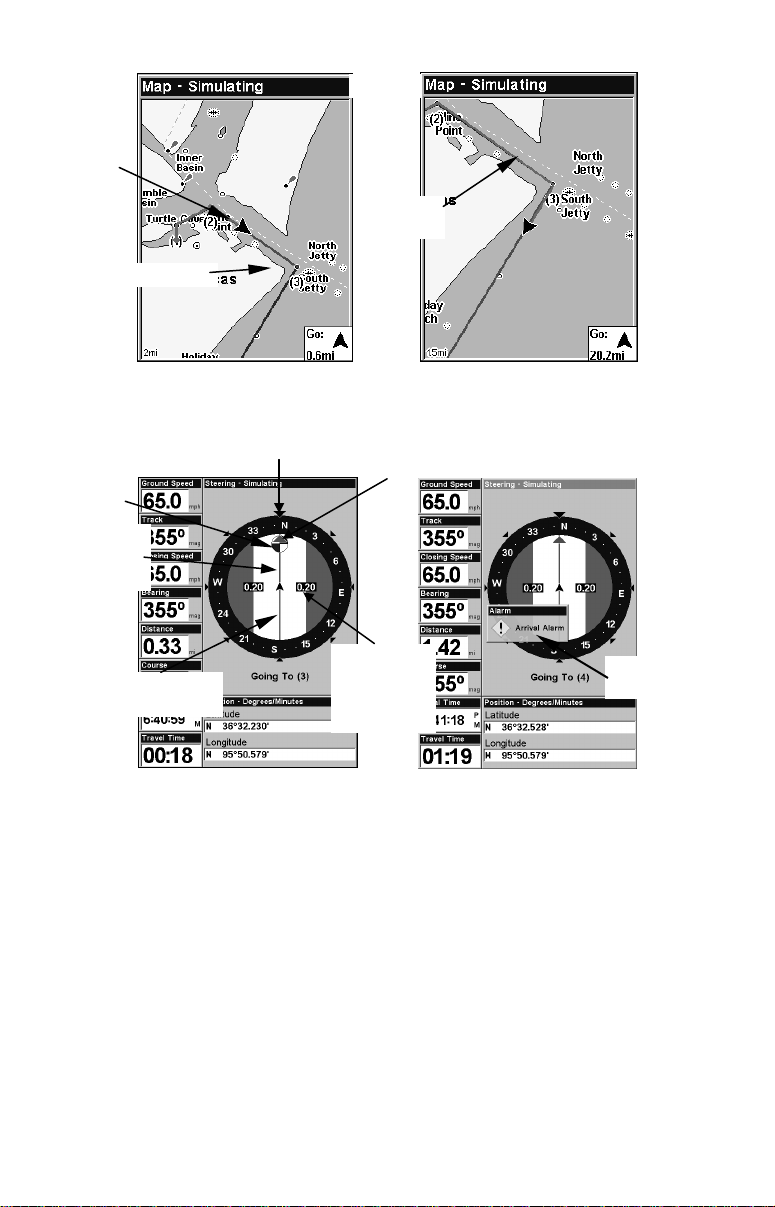
North
Present
position
arrow
Magenta
trail line
Trail point
Navigate trail: Driver is heading southeast straight toward trail point
3 (left). Driver has reached point 3 and has turned southwest to follow
the trail (right).
Trail
waypoint
symbol
Red course
line made
from trail
Track or compass heading indicator
Bearing arrow
Magenta new
trail
Cross track
error range
(off course
indicator)
Arrival
alarm
Navigate trail, navigation page (compass rose) views: Driver is heading
north straight toward trail point 3 (left). Bearing arrow shows the
bearing to the trail point is 355 degrees. Driver has reached trail point
3 (right), causing the Arrival alarm to go off. The unit now shows
navigation information to point 4, which is 1.42 miles away.
Navigate a Back Trail
1. Press
MENU|MENU|↓ to MY TRAILS|ENT.
2. Press ↓ to enter the Saved Trail list, then use ↑ ↓ to select the desired Trail Name|
3. Press ↓ → to
4. Press ↓ → to
ENT.
NAVIGATE|ENT.
REVERSE ROUTE|ENT|← to NAVIGATE|ENT. The unit shows
navigation information along the trail, in reverse.
49
Page 56

NOTE:
If you are already located at or near the end of your trail, the arrival alarm will go off as soon as you hit Enter. Just press
EXIT to
clear the alarm and proceed.
5. Now, begin moving and let your unit guide you.
6. When you reach your destination, be sure to cancel your navigation.
Press
MENU|MENU|↓ to CANCEL NAVIGATION|ENT. A confirmation message
will appear. Press ←|
ENT.
Transfer Custom Maps and GPS Data Files
Custom Maps:
Custom maps work only from the MMC card or SD card. When a card
containing a Custom Map File is loaded into the unit, the unit automatically loads the map into memory when the unit is turned on.
Instructions for copying Custom Map Files to an MMC are contained in
the instruction manual for your MMC card reader and MapCreate 6
software. For instructions on inserting an MMC into the unit, see Sec.
2, Installation/Accessories.
GPS Data files:
GPS Data Files contain waypoints, routes, trails and event marker
icons. Instructions for copying GPS Data Files between your computer
and an MMC are contained in the instruction manual for your MMC
card reader and MapCreate 6 software.
You must enter which way you want to transfer data, from an MMC
card to the unit (load) or from the unit to an MMC card (save).
GPS data automatically recorded in the unit's internal memory must be
saved to the MMC (as a GPS Data File) in order to store it on your personal computer. GPS Data Files stored on an MMC must be copied from
the card to the unit's internal memory before the unit can read them.
50
Page 57

1. Insert the MMC into your unit. Press
SETUP|ENT|↓ to TRANSFER MY DATA|ENT.
MENU|MENU|↓ to SYSTEM
2. The Transfer My Data menu includes a message which tells you if an
MMC is present or not. If no MMC is present, you must insert a card
into the unit to activate the Load or Save commands.
To transfer data from the unit to the MMC: press
To transfer data from the MMC to the unit: press → to
ENT (for SAVE.)
LOAD|ENT.
3. Saving to MMC: To accept the default name "Data" for the GPS
Data File, press ↓ to
shown in the following figures), press
SAVE DATA|ENT. If you want to rename the file (as
ENT to activate the selection box.
Press ↑ ↓ to change the first character, then press → to the next character and repeat until the name is correct. Then press
DATA|ENT.
ENT|↓ to SAVE
The unit will display first a progress then a completion message when
the data transfer is finished. To return to the Page view, repeatedly
press
EXIT.
These figures (from left to right) show the menu sequence for naming
and saving a GPS Data File from the unit's memory to an MMC.
4. Loading to unit memory: There may be more than one GPS Data
File (*.USR) on the card. To select a file, press
tion box, use ↓ ↑ to highlight the file, then press
lection. Next, press ↓ to
LOAD DATA|ENT. The unit will display a comple-
ENT to activate the selec-
ENT to accept the se-
tion message when the data transfer is finished. To return to the main
page display, press
EXIT repeatedly.
51
Page 58

Figure 1.
Figure 2.
Figure 3.
Figure 4.
These figures show the menu sequence for loading a GPS Data File
from an MMC into the unit's memory.
Cancel Navigation
You can turn off any of the navigation commands after you reach your
destination or at any other time by using the Cancel Navigation command. Press
MENU|MENU|↓ to CANCEL NAVIGATION|ENT|← to YES|ENT.
52
Page 59

Section 4:
Advanced GPS Operations
Find Distance Current Position to Another Location
1. While on the Map Page press MENU|↓ to FIND DISTANCE|ENT.
2. Center the cursor crosshairs on the position you want to find the distance to. A rubber band line appears, connecting your current position
to the cursor's location. The distance along that line will appear in a
pop-up box. The box also shows the bearing to the point selected by the
cursor.
3. Press
EXIT|EXIT to return to regular operation.
The distance from the boat's current position to the cove is 5.78 miles
(left). The distance from Houston to New Orleans is 316.9 miles (right).
Find Distance From Point to Point
You can also measure distance between two other points on the map.
1. While on the Map Page press
2. Center the cursor crosshairs on the first position. A rubber band line
appears, connecting your current position to the cursor's location. Press
ENT to set the first point and the rubber band line disappears.
3. Move the cursor to the second position. The rubber band line reappears, connecting the first point you set to the cursor. The distance
along that line will appear in the pop-up box.
4. Press
EXIT|EXIT to return to regular operation.
MENU|↓ to FIND DISTANCE|ENT.
53
Page 60

Icons
Icons are graphic symbols used to mark some location, personal point of
interest or event. They can be placed on the map screen, saved and recalled later for navigation purposes. These are sometimes referred to as
event marker icons. This unit has 42 different symbols to choose from
when creating an icon.
Icons are similar to waypoints, but they do not store as much information (like names) as waypoints do. You can not use a menu to navigate
to icons as you can with waypoints. But, you can use the map cursor
and navigate to any icon on the map.
You can create an icon at the cursor position on the map or at your current position while navigating.
Create Icon on Map
1. Use the arrow keys to move the cursor to the place where you want
to make an icon.
2. Press
3. Select the desired icon symbol and press ENT. The icon appears on
the map. Press
ENT and the screen shows the Select Icon Symbol menu.
EXIT to clear the cursor.
Cursor selects icon location (left). Select Icon Symbol menu (center).
Boat Ramp icon on map (right). (Cursor has been moved for clarity.)
Create Icon at Current Position
1. While you are traveling, press ENT and the screen shows the Select
Icon Symbol menu.
2. Select the desired icon symbol and press
ENT. The icon appears on
the map.
Delete an Icon
You can delete all the icons at one time, all icons represented by a particular symbol or use the cursor to delete a selected icon from the map.
54
Page 61

Delete icons menu.
1. Press MENU|↓ to DELETE MY ICONS|ENT.
2. Press ↓ to
press
ENT.
DELETE ALL ICONS, DELETE BY SYMBOL or DELETE FROM MAP and
3. The Delete All Icons confirmation message will appear. Press ← to
YES|ENT. All icons will be deleted from the map.
The Delete by Symbol command will launch the Select Symbol menu.
Select the desired icon symbol to delete and press
ENT. A message ap-
pears saying all icons with the selected symbol have been deleted.
The Delete From Map command will prompt you to move the cursor
over an icon to select it. After selecting the icon, press
ENT and it disap-
pears from the map.
Navigate to an Icon
To execute the Navigate to Cursor command, use the cursor to select
the desired icon on the map.
1. Center cursor crosshairs on an icon.
2. To navigate to the icon press
MENU|ENT|EXIT. Follow the course line
on the Map Page or the compass bearing arrow on the Navigation Page.
Routes
A route is a series of waypoints, linked together in an ordered sequence
used to mark a course of travel. You can visualize a route as a string of
beads. The beads represent waypoints and the string represents the
course of travel connecting waypoint to waypoint. The course from one
waypoint to the next is a leg. Routes are composed of one or more legs.
The legs of all GPS routes are based on straight lines between waypoints.
55
Page 62

A route allows you to navigate through several waypoints without
having to reprogram the unit after arriving at each waypoint. Once
programmed into the GPS unit, a route provides the option of navigating forward through the route waypoints or in reverse order. You can
even begin navigating in the middle of a route.
Create and Save a Route
You have the option of creating and editing a route in the unit or you
can make a route on your computer with our MapCreate 6 software.
PC-created Routes
MapCreate is the easiest method for preparing a route, because your
PC's larger screen, keyboard and mouse are easier to manipulate than
the unit.
To load a MapCreate route into the unit, follow instructions in MapCreate's manual for creating a route and saving it as part of a GPS Data File
(file format *.usr). Copy the GPS Data File to an MMC and insert the
MMC in the unit. (See Sec. 2 for instructions on installing MMCs. To
load the GPS Data File into the unit's memory, see the entry on Transfer
Custom Maps & GPS Data Files in Sec. 6, Basic GPS Operations.)
Routes Created in the Unit
You can create a route by selecting existing waypoints from the waypoint list or you can set a series of route waypoints on the map with
cursor arrows and the Enter key. In this example, we will create a
route from the map.
1. From the
press
MENU|MENU|↓ to ROUTE PLANNING|ENT.
NAVIGATION PAGE, press MENU|ENT or from the MAP PAGE,
Route Planning command on Main Menu (left).
Route List menu (right).
56
Page 63
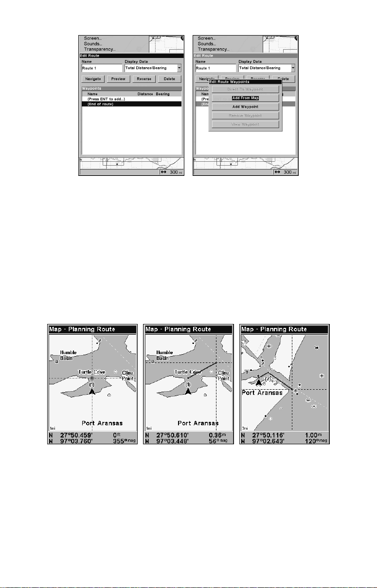
Edit Route menu (left). Edit Route Waypoints menu (right)
with Add From Map command selected.
2. Press ↑ to NEW ROUTE, then press ENT. (To add to an existing route,
press ↓ ↑ to route name|
3. Press ↓ to
END OF ROUTE|ENT|↓ to ADD FROM MAP|ENT. The Map Page
ENT.)
appears with the cursor showing.
4. Use the Zoom and arrow keys to move the map and cursor until the
cursor is centered on the spot where you want your route to begin.
5. To set the first route waypoint press
ENT. In the example below, we
moved to the entrance of the cove where our boat was docked.
1.
2.
3.
Route creation sequence: Fig. 1. Set route waypoint (1) at the cove en-
trance. Fig. 2. Move cursor northeast to set point (2) at channel en-
trance. Fig. 3. With point (2) set, move cursor southeast to mark chan-
nel exit with waypoint (3). In figures 2 and 3, notice the rubber band
line extending from the previously set waypoint to the cursor. This
line will become the course for the route.
57
Page 64

4.
5. 6.
Route creation sequence, continued: Fig. 4. Point (3) set at channel
mouth. Fig. 5. Waypoint (4) set further south along the beach, at a rec-
ognizable landmark (Bob Hall Pier). Waypoint PLFM Q W ends the
route at an oil platform some distance from the shore. Fig. 6. Press EXIT
to save the route and you return to this screen.
6. Move the cursor to the next point in the route, a spot where you need
to turn or change direction and press
ENT to set the next waypoint.
7. Repeat step six until the route reaches your destination.
8. To save your route, press
EXIT. The unit reverts to the Edit Route
screen, with the route automatically named "Route 1" and stored in the
unit's internal memory.
You can edit the route and run other commands, but if you are finished
with the route for now, return to the main page display by
pressing
EXIT repeatedly.
NOTE:
When adding waypoints to an existing route, the inserted waypoints will appear in the route in front of the waypoint you have
selected in the Edit Route menu. To insert waypoints at the end of
the route, make sure to select
(END OF ROUTE) before adding them.
Delete a Route
1. From the
NAVIGATION PAGE, press MENU|ENT or from the MAP PAGE
press MENU|MENU|↓ to ROUTE PLANNING|ENT.
2. Press ↓ to saved route name|
3. Highlight
DELETE |ENT|← to YES|ENT.
ENT.
To Delete All Routes at Once:
1. From the
NAVIGATION PAGE, press MENU|ENT or from the MAP PAGE
press MENU|MENU|↓ to ROUTE PLANNING|ENT.
2. Highlight
DELETE ALL|ENT|← to YES|ENT.
58
Page 65

Edit a Route Name
1. From the
NAVIGATION PAGE, press MENU|ENT or from the MAP PAGE
press MENU|MENU|↓ to ROUTE PLANNING|ENT.
2. Highlight Saved Route Name|
ENT|↑ to Name|ENT.
3. Press ↑ ↓ to change the first character, then press → to move to the
next character and repeat until the name is correct. Press
turn to the main page display press
EXIT repeatedly.
ENT. To re-
Edit Route Waypoints
You can edit the route by adding and removing waypoints.
1. From the
NAVIGATION PAGE, press MENU|ENT or from the MAP PAGE
press MENU|MENU|↓ to ROUTE PLANNING|ENT.
2. Press ↓ to saved route name|
to select a waypoint and press
ENT|↓ to Route Waypoints List. Use ↓ ↑
ENT.
Edit Route Waypoints menu.
3. Use ↓ ↑ to select a command from the Edit Route Waypoints menu
and press
ENT. Add From Map lets you insert a waypoint in the route.
Add Waypoint calls up the Waypoint List so you can insert a waypoint
from the list. Remove Waypoint will delete the waypoint from the route.
View Waypoint will show you where the waypoint is on the map.
NOTE:
When adding waypoints to a route, the inserted waypoints will appear in front of the waypoint you have selected. To insert waypoints
at the end of the route, select
(ROUTE END) before adding them.
Navigate a Route
1. From the
press
MENU|MENU|↓ to ROUTE PLANNING|ENT.
NAVIGATION PAGE, press MENU|ENT or from the MAP PAGE,
59
Page 66

Route Planning command on Main Menu (left). Routes menu (center).
Edit Route menu (right) with Navigate Route command selected.
2. Press ↓ to select saved route name|ENT. Highlight NAVIGATE and press
ENT.
3. Upon arrival at your destination, cancel navigation.
Press
MENU|MENU|↓ to CANCEL NAVIGATION|ENT|← to YES|ENT.
Figure 1.
Figure 2.
Navigating along a route: Fig. 1 shows the Navigation Page at the start
of a route, heading straight for the first waypoint (Wpt 1). In
Fig. 2, the traveler has arrived at Wpt 1; the arrival alarm has been trig-
gered and the bearing arrow on the compass rose has turned to point
toward Wpt 2, off to the northeast.
60
Page 67

Figure 3.
Figure 4.
In Fig. 3 the traveler has turned northeast on his new course and is
heading straight for Wpt 2, which is 0.20 miles away. Fig. 4 shows route
navigation on the Map Page. In this figure, the traveler has reached Wpt
2 and is starting on the leg between Wpts 2 and 3.
Navigate a Route in Reverse
Here's how you run a route backward, from the end waypoint to the
beginning waypoint:
1. From the
press
MENU|MENU|↓ to ROUTE PLANNING|ENT.
2. Press ↓ to saved route name|
NAVIGATE |ENT.
NAVIGATION PAGE, press MENU|ENT or from the MAP PAGE,
ENT. Press ↓ → to REVERSE|ENT|← to
3. Upon arrival at your destination, cancel navigation:
press
MENU|MENU|↓ to CANCEL NAVIGATION|ENT|← to YES|ENT.
Edit Route screen showing Route 1 with waypoints set to normal navi-
gation (left). Reverse command has been executed (center) reversing the
order of waypoints on the route. Pressing Navigate (right) will allow
you to navigate the route from the end to the beginning.
61
Page 68

Trails
Delete a Trail
This is the command used to erase or delete a trail.
Press
DELETE TRAIL|ENT|← to YES|ENT.
To Delete all trails at once:
Edit a Trail Name
To edit a trail name press
name|
to the next character and repeat until the name is correct. Press
then EXIT repeatedly to get back to the main page display.
Tip:
MENU|MENU|↓ to MY TRAILS|ENT|↓ to trail name|ENT|→ to
1. Press
2. Press → to
MENU|MENU|↓ to MY TRAILS|ENT.
DELETE ALL|ENT|← to YES|ENT.
MENU|MENU|↓ to MY TRAILS|ENT|↓ to trail
ENT|ENT. Press ↑ ↓ to change the first character, then press →
ENT
You can quickly call up the Edit Trail menu by selecting a trail on
the map with the cursor. Move the cursor over a trail and a pop-up
box appears. Press
WPT and the Edit Trail menu opens.
Trail selected with map cursor (left). The box at the bottom of the
screen shows distance and bearing from current position to the se-
lected point on the trail. The Edit Trail menu (right).
Edit a Trail Color
To edit a trail color press
name|
ENT. Press EXIT repeatedly to return to the main page display.
ENT|↓ to COLOR|ENT. Press ↑ ↓ to select a color style, then press
MENU|MENU|↓ to MY TRAILS|ENT|↓ to trail
62
Page 69

Edit a Trail Pattern
To edit a trail pattern press
name|
ENT|↓ to PATTERN|ENT. Press ↑ ↓ to change the first character,
MENU|MENU|↓ to MY TRAILS|ENT|↓ to trail
then press → to the next character and repeat until the pattern is correct. Press
ENT. To get back to the main page press EXIT repeatedly.
Edit Trail Menu with Pattern option selected (left). Edited trail with
dotted line pattern (right).
Utilities
Utilities are useful tools for traveling or for outdoor activities.
Alarm Clock
To get to the alarm clock menu press
to
ALARM CLOCK|ENT.
MENU|MENU|↓ to TIMERS|ENT|↓
Sun/Moon Rise & Set Calculator
To get to the Sun/Moon menu press
CALCULATIONS|ENT.
MENU|MENU|↓ to SUN/MOON
Trip Calculator
To get to the Calculator menu press
CALCULATOR|ENT.
Trip Down Timer
To get to the Down Timer menu press
to
DOWN TIMER|ENT.
MENU|MENU|↓ to TIMERS|ENT|↓
Trip Up Timer
To get to the Up Timer menu press
MENU|MENU|↓ to TIMERS|ENT|ENT.
63
MENU|MENU|↓ to TRIP
Page 70

Waypoints
Delete a Waypoint
To delete a waypoint from the waypoint list press
WAYPOINTS|ENT|↓ to Name|ENT. Press ↑ ↓ to select the desired charac-
WPT|↑ to MY
ter then press → to choose the next character. After the desired waypoint is highlighted in the list, press
WAYPOINT then press |ENT|← to YES|ENT. To return to the main page
display, press
EXIT repeatedly.
ENT|ENT. Use ↓ to select DELETE
To delete a waypoint from the map:
1. Use the arrow keys to select a waypoint with the cursor.
2. Press
WAYPOINT|ENT|← to YES|ENT. To return to the main page display, press
EXIT repeatedly.
To delete all waypoints at one time, press
SETUP|ENT|↓ to DELETE ALL MY WAYPOINTS|ENT|← to YES|ENT. To return
to the previous page, press
WPT to view the WAYPOINT INFORMANTION screen, then ↓ to DELETE
MENU|MENU|↓ to SYSTEM
EXIT|EXIT.
Edit a Waypoint
To edit waypoint name:
1. Press
WPT|↑ to MY WAYPOINTS|ENT|↓| to name|ENT. Choose desired
waypoint from the list by using ↑ ↓ to select first character, then press
→ to choose the next character. After the desired waypoint is high-
lighted in the list, press
ENT|ENT to access waypoint information
screen.
2. Use ↓ to select
EDIT WAYPOINT, then press ENT|ENT. Press ↑ ↓ to
change the first character, then press → to the next character and repeat until the name is correct. Press
display, press
EXIT repeatedly.
ENT. To get back to the main page
To edit waypoint symbol:
1. Press
from the list then press
Press|
WPT|↑ to MY WAYPOINTS|ENT|↓ to name|ENT. Select waypoint
ENT|ENT. Use ↓ to select EDIT WAYPOINT.
ENT|↓ to CHOOSE SYMBOL|ENT.
2. Select the desired symbol and press
page display, press
EXIT repeatedly.
To edit waypoint position:
1. Press
waypoint and press
WPT|↑ to MY WAYPOINTS|ENT|↓ to name|ENT. Select the desired
ENT|ENT. Press ↓ to EDIT WAYPOINT|ENT.
64
ENT. To get back to the main
Page 71

2. Latitude: press → to
LATITUDE|ENT. Press ↑ ↓ to change the first char-
acter, then press → to the next character and repeat until the latitude
is correct. Press
3. Longitude: press ↓ to
EXIT.
LONGITUDE|ENT. Press ↑ ↓ to change the first
character, then press → to the next character and repeat until the longitude is correct. Press
EXIT repeatedly.
EXIT. To return to the main page display, press
Selecting a Waypoint
To select a waypoint on the map center the cursor crosshairs on the
waypoint. A red border will appear around the waypoint.
Set a Waypoint by Average Position
A waypoint set by average position is created after several position
readings have been averaged. This boosts waypoint position accuracy
by helping to eliminate errors caused by atmospheric conditions and
other factors.
1. Press
WPT|↑ to MY WAYPOINTS|→ to NEW|ENT.
2. Press ↓ ↑ to
AVERAGE POSITION|ENT|press → to CREATE|ENT.
3. Wait while the unit takes points to get an average for the position. The
greater the number of points, the greater the accuracy. When the desired
number of points accumulates, press
4. The Edit Waypoint menu appears. Press
ENT to create the waypoint.
EXIT repeatedly to get back
to the main page display.
Set a Waypoint by Projecting a Position
This feature creates a waypoint at a location a specific distance and
bearing from a reference position. The reference position can be a waypoint, map feature or Point of Interest.
1. Press
2. Press ↓ to
3. Select
ture or Point of Interest. When a selection has been made press
WPT|↑ to MY WAYPOINTS|→ to NEW|ENT.
PROJECTED POSITION|ENT|→ to CREATE|ENT.
CHOOSE REFERENCE|ENT. Use ↑ ↓ to select a waypoint, map fea-
ENT.
Press →, ↑ ↓ to choose a subcategory, then press ENT. Highlight
NAME|ENT. Spell out the name of the desired reference point in the Find
By Name box or press
you have selected a point, press
information window. Highlight
ENT to the find the point in the list below. After
ENT. That will launch the waypoint
SET REFERENCE and press ENT.
65
Page 72

4. Press ← ↓ to
DISTANCE|ENT. Press ↑ ↓ to change the first character,
then press → to the next character and repeat until the distance is correct. Press
ENT.
5. Press ↓ to
BEARING|ENT. Press ↑ ↓ to change the first character, then
press → to the next character and repeat until the bearing is correct.
Press
ENT.
6. Press ↑ to
EXIT|EXIT to get back to the main page display or press EXIT|ENT to
PROJECT|ENT. The Edit Waypoint menu appears. Press
navigate to the new waypoint.
66
Page 73

Section 5:
System & GPS Setup Options
Alarms
This unit has three GPS alarms: Arrival Alarm, Off Course Alarm and
Anchor Alarm — the only one of the three set to Off by default.
You can set an arrival alarm to flash a warning message and sound a
tone when you cross a preset distance from a waypoint. For example, if
you have the arrival alarm set to .1 mile, the alarm will flash a message when you come within .1 mile of your destination.
The off course alarm warns you when your track drifts too far to the
right or left of the course line to your destination. For example, if the
alarm is set to .1 mile, then the alarm flashes a message if you drift .1
miles or more to the right or left of the course line.
The anchor alarm is triggered when you drift outside of a preset radius.
If you are anchored and your boat moves more than .1 miles, the alarm
will flash a message and sound a tone.
Alarms command (left). Alarm menu (right).
To change alarm settings:
1. Press
2. Scroll ↓ ↑ to select the desired category, then press
(check) or turn off (uncheck) the desired alarm.
3. To change distance settings, select the desired alarm, then press
→|
character, then press → to the next character and repeat until you are
MENU|MENU|↓ to ALARMS|ENT.
ENT to turn on
ENT to activate the distance dialog box. Press ↑ ↓ to change the first
67
Page 74

satisfied with the distance setting. If you want to enable the other
alarms, repeat steps 2 and 3.
4. Press
EXIT repeatedly to get back to the main page display.
IMPORTANT ALARM NOTES:
Anchor Alarm - The anchor alarm may be triggered even when you
are sitting still. This usually happens when using small — less than
.05 mile — anchor alarm ranges.
Arrival Alarm - If the arrival alarm distance is set to a small number, the unit may not show navigation data to the next waypoint after you arrive at the first one. That occurs when you are not able to
come close enough to the first waypoint to trip the arrival alarm.
Check MMC Files and Storage Space
To check MMC Files:
Press
MENU|MENU|↓ to BROWSE MMC FILES|ENT. Press ↓ to MMC CARD
INFO|ENT to see the free space on the card.
Main Menu (left). MMC File Browser (right).
Communications Port Configuration
This unit has one NMEA 0183 version 2.0 compatible communication
port. The Com Port Menu, accessed from the System Setup Menu, allows you to configure the communications port to send or receive data
to another electronic device. The com port can be used for NMEA or
SiRF Binary data transfer.
To set Com Port Configuration:
1. Press
2. Press ↓ to
MENU|MENU|↓ to SYSTEM SETUP|ENT.
COMMUNICATIONS PORT|ENT.
68
Page 75

Menus for changing Com Port settings.
For assistance in configuring the unit to communicate with another
device, consult the factory. Customer service phone numbers are in the
back of this manual. Also see the entry below for Configure NMEA.
Configure NMEA
You can configure the unit to use specific NMEA sentences.
1. Press
2. Press ↓ to
MENU|MENU|↓ to SYSTEM SETUP|ENT.
COMMUNICATIONS PORT|ENT|↓ to CONFIGURE NMEA 0183|ENT.
3. A menu appears showing the prefixes of the available NMEA sentences. A check mark next to a prefix means the prefix is in use. Use ↑
↓, ← → to select a prefix, then press
ENT to turn it on or off.
NOTE:
The names of the NMEA sentences are abbreviated in this menu.
These are the functions of the various selectable prefixes:
• GLL transmits latitude and longitude of present position, time
of position fix, and status.
• RMC and RMB transmits navigation information messages.
• APB transmits autopilot information.
• GGA transmits time, position, and fix related data.
• GSA and GSV transmits fix mode, DOP values, and satellites in
view information.
• DBT transmits the depth below the transducer.
• DPT transmits the depth
• MTW transmits the water temperature.
69
Page 76

• VLW transmits the distance traveled through water as meas-
ured by the paddle wheel.
• VHW transmits the water speed as measured by the paddle
wheel.
4. When the desired prefixes are turned on, press
EXIT repeatedly to get
back to the main page display.
Coordinate System Selection
The Coordinate System Menu lets you select the coordinate system to
use when displaying and entering position coordinates.
Menus used for changing coordinate system.
To get to Coordinate System Selection:
1. Press
2. Press ↓ to
This unit can show a position in degrees (36.14952°); degrees, minutes
and thousandths of a minute (36° 28.700'); or degrees, minutes, seconds
and tenths of a second (36° 28' 40.9"). It can also show position in: UTM
(Universal Transverse Mercator) projection; MGRS (Standard); MGRS
(Standard + 10); Map Fix; Loran TD; British, Irish, Finnish, German,
New Zealand, Swedish, Swiss, Taiwan and Greek grid systems.
UTM's are marked on USGS topographic charts. This system divides
the Earth into 60 zones, each 6 degrees wide in longitude.
British, Irish, Finnish, German, New Zealand, Swedish, Swiss, Taiwan,
and Greek grid systems are the national coordinate system used only in
their respective countries. In order to use these grid systems, you must
be in the respective country. This unit will pick the matching datum for
you when you select the grid. See the entry on Map Datum Selection for
more information.
MENU|MENU|↓ to GPS SETUP|ENT.
COORDINATE SYSTEM|ENT.
70
Page 77

The Military Grid Reference System (MGRS) uses two grid lettering
schemes, referred to as standard and standard + 10 MGRS on this unit.
Your position and datum in use determines which one to use. If you use
standard and your position is off significantly, then try the alternate.
NOTE:
When the position format is changed, it affects the way all positions
are shown on all screens, including waypoints.
To change the coordinate system, press
highlighted. Use ↑ ↓ to highlight the desired format. Press
ENT while COORDINATE SYSTEM is
ENT to select
it.
To setup Loran TD:
NOTE:
If the Loran TD conversion is chosen, you must enter the local Loran chain identification for the master and slaves. Do this by selecting Setup Loran TD at the bottom of the Coordinate System
menu, then selecting the desired ID. Press
EXIT to close this menu.
Configure Loran TD menu.
Customize Page Displays
Every Page display option except Full Map page option has customizable data boxes to provide constant on-screen information.
To change the information displayed in a data box:
On the page with a digital data box you want to change, press
to
CUSTOMIZE|ENT.
1. A data box name flashes, indicating it is selected. Press ENT to
change the data in that box or use ↑ ↓, ← → to select another box to
customize. With the desired data box highlighted and flashing, press
ENT to access the Data Viewer menu.
71
MENU|↓
Page 78
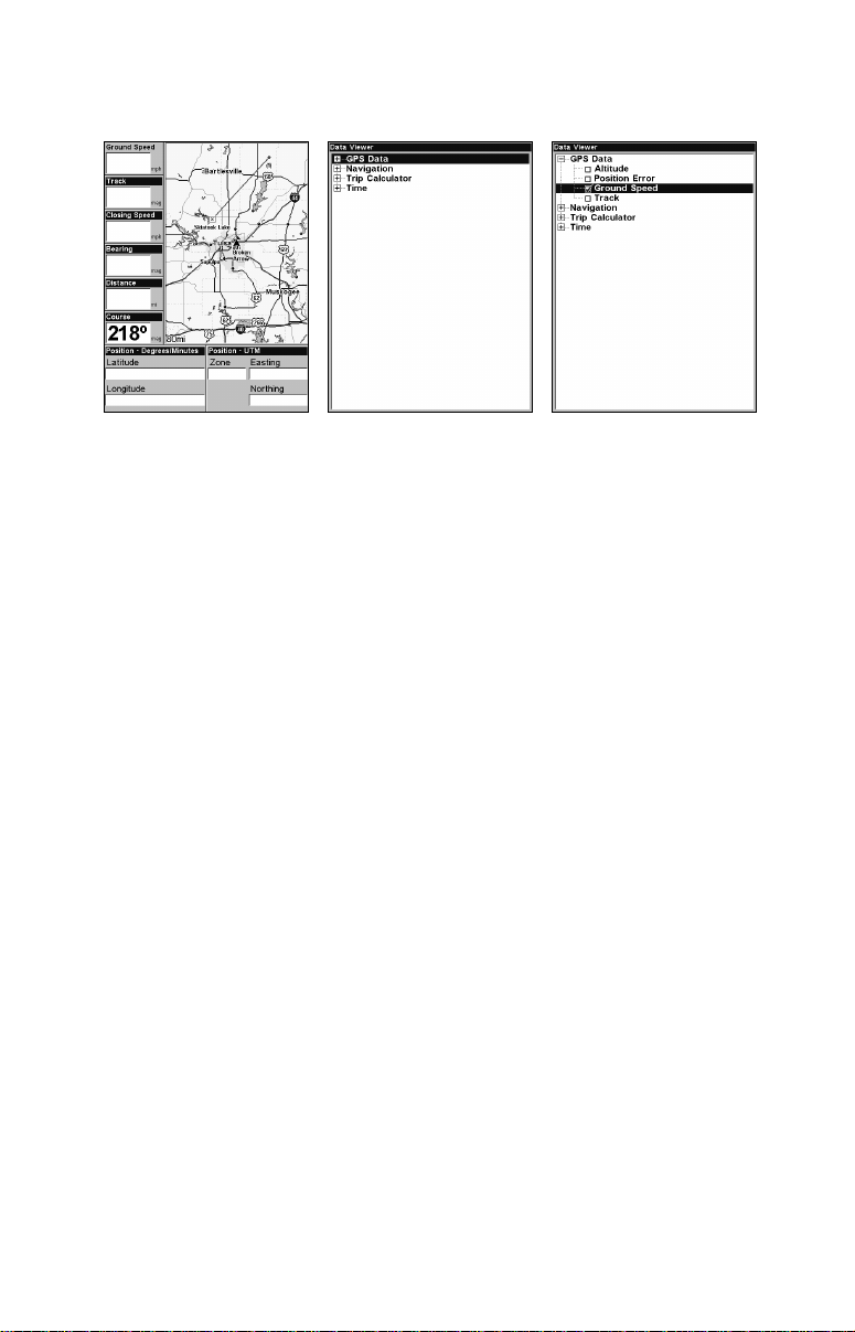
The Data Viewer menu has four categories: GPS Data, Navigation, Trip
Calculator and Time. Each category has its own data option menu.
Ground Speed flashing on Two Position Map page (left). Data Viewer
menu with no open categories (center). GPS data category opened with
Ground Speed selected (right).
2. Select a data category. If the desired category is flanked by a "+", a
list of data options will appear when you highlight the category and
press
ENT. After opening a category it will have a "–" next to it. To close
the category, highlight it and press
ENT.
4. Open the desired category and use ↑ ↓ to select the desired data option and press
press
EXIT.
ENT to turn it on (check) or turn it off (uncheck) and
5. If you want to change the data in another digital data box, use ↑ ↓
and press
with the current display, press
ENT when the desired box is highlighted. If you are satisfied
EXIT to return to normal operation.
A Page display can show a limited number of data boxes. You can not
turn them off or add more data boxes.
GPS Simulator
The GPS simulator simulates real world navigation. It is a great way to
practice using your unit. You can set the starting location by entering
latitude/longitude or from a stored waypoint, map place or POI location.
You can steer the position arrow and change speed on the map by using
the arrow keys —
and speed in the dialog boxes provided on the simulator menu screen.
To get to the GPS Simulator:
1. Press
MENU|MENU|↓ to GPS SETUP|ENT.
2. Press ↓ to
STEER WITH ARROWS command — or by setting the track
GPS SIMULATOR|ENT. The GPS Simulator Menu appears.
72
Page 79

GPS Setup Menu (left). GPS Simulator menu (center).
Map Page showing Steer with Arrows dialog boxes (right). The trav-
eler is following a track of 144º at a speed of 71 miles per hour.
Choose the desired settings, then turn on the simulator by highlighting
the
GPS SIMULATOR ON box and pressing ENT. Press EXIT repeatedly to get
back to the main page display. A message and tone appear periodically
to remind you the simulator is on. To turn off the simulator, repeat the
steps above or turn off the unit.
If you selected the Steer with Arrows command and want to remove the
dialog boxes from the screen, press
EXIT. That will clear the track and
speed boxes without disrupting the simulation and allow you to use the
map cursor.
Simulating Trail or Route Navigation
In Simulator mode, your unit can automatically follow a trail or route
without manual steering if you use these steps:
1. From the Map Page, go to the simulator menu. Pick a
POSITION at or near the beginning of your trail/route. Enter an approxi-
mate
TRACK (shown in compass degrees) that will point you toward the
STARTING
start of the trail/route.
2. Set
SPEED to zero. Select STEER WITH ARROWS command and press ENT,
which turns on the simulator and returns you to the Map Page.
3. Begin navigating along the trail/route. (If you are close enough to the
first waypoint, the arrival alarm will usually go off as soon as navigation begins. Press
EXIT to clear the alarm.) When navigation starts,
press ↑ to increase speed to the desired setting.
4. Press
EXIT to turn off the steering and speed boxes. The unit will now
automatically steer along the trail or route. When you arrive at your
destination, cancel navigation.
73
Page 80

Tip:
You can pick any spot on the map to begin a simulation by using
the Initialize GPS command. It allows you to move the position arrow to any location on the map. The command is detailed below.
Initialize GPS
In simulator mode, the Initialize GPS command makes the unit operate
as if it is sitting someplace other than its actual location. So you and
your unit could be located in Kansas City, but practice navigating in the
ocean off Islamorada, Florida.
NOTE:
Remember: if you want to run a simulation in a place other than
your current location, you first must Initialize the GPS, then turn
on the GPS Simulator.
1. Press
2. A message appears, telling you to move the cursor near the desired
location and press
the message instructions.
3. In a moment, your present position marker arrow appears on the
map in the location you selected with the cursor. The unit will consider
that spot as its last known position until changed by either a live satellite lock-on or a new simulator location.
MENU|MENU|↓ to GPS SETUP|ENT|ENT.
ENT. When the message automatically clears, follow
Map Auto Zoom
This receiver has an auto zoom feature that eliminates a lot of the button pushing common with other brands of GPS receivers. It works in
conjunction with the navigation features.
Start navigating to a waypoint. Then, with the auto zoom mode on, the
unit zooms out until the entire course shows, from the present position
to the destination waypoint. As you travel toward the destination, the
unit automatically zooms in — one zoom range at a time — keeping
your current position and the destination on the screen.
To turn this feature on from the
ZOOM|ENT|EXIT. Repeat these steps to turn it off.
MAP PAGE, press MENU|↓ to AUTO
Map Data
From the Map Data menu, you can turn off the map — which will turn
the map into a GPS plotter — turn on or off pop-up map info boxes,
draw map boundaries and fill water areas with white. You also can
turn on or off Map Overlays, like range rings and latitude and longitude grid lines.
74
Page 81

Map menu (left). Map Data menu (right).
From the Map Page, you can access the Map Data menu by pressing
MENU|↓ to MAP DATA|ENT.
Earth Map Detail
From the Map Data menu, highlight
EARTH MAP DETAIL and press ENT.
Select the desired level of map detail from four options: Off, Low, Medium or High. After the option is set, press
EXIT.
Pop-up Map Information
From the Map Data menu, highlight
ENT to turn it on (check) or turn it off (uncheck). After the option is set,
press
EXIT.
POPUP MAP INFORMATION and press
Draw Map Boundaries
From the Map Data menu, highlight
DRAW MAP BOUNDARIES and press ENT
to turn it on (check) or turn it off (uncheck). After the option is set,
press
EXIT.
Fill Water With White
From the Map Data menu, highlight
ENT to turn it on (check) or turn it off (uncheck). After the option is set,
press
EXIT.
FILL WATER WITH WHITE and press
Map Overlays (Range Rings; Lat/Long Grid)
The map screen can be customized with four range rings and/or grids
that divide the map into equal segments of latitude and longitude.
Range rings are handy for visually estimating distances on the map. The
ring diameters are based on the current zoom range. At a 100-mile zoom,
the screen will show two rings with your current position in the center.
The large ring touching the left and right sides of the screen is 100 miles
75
Page 82

in diameter (same as the zoom range). The second smaller ring is 50
miles in diameter (always 1/2 the zoom range).
The distance from your current position to the smaller ring (the ring's
radius) is 25 miles (always 1/4 the zoom range). With the map cursor,
you can scroll over to see the third and fourth rings. In this example,
the distance to the third ring is 75 miles and distance to the fourth ring
is 100 miles from your current position.
To set range rings: From the Map Data menu, highlight
RANGE RINGS
and press ENT to turn them on (check) or turn them off (uncheck). After
the option is set, press
To set Lat/Long Grid: From the Map Data menu, highlight
GRID LINES and press ENT to turn them on (check) or turn them off (un-
check). After the option is set, press
EXIT.
LAT/LON
EXIT repeatedly to get back to the
main page display.
Map Datum Selection
Maps and charts are based on a survey of an area covered by a map or
chart. These surveys are called Datums. Maps created using different
datums will show the same latitude/longitude in slightly different locations.
All datums have a name. The GPS system is based on the WGS-84 datum, which covers the entire world. Other datums may cover the entire
world or just a small portion of it. By default, your position is shown
with the WGS-84 datum. It, however, can show your position using any
of 191 different datums.
To change the Datum:
1. Press
2. Select the desired datum and press
3. To return to the main page display, press EXIT|EXIT.
A list of the datums used by this unit is in the back of this manual.
MENU|MENU|↓ to GPS SETUP|ENT|↓ to DATUM SELECTION|ENT.
ENT.
76
Page 83

GPS Setup Menu (left). Map Datum Menu (right).
Map Detail Category Drawn
This menu determines what mapping features are shown on the screen.
This includes, waypoints, trails, icons, cities and highways, etc. You can
turn on or off any of these items, customizing the map to your needs.
Map Menu (left). Map Categories Drawn Menu (right).
To get to Map Categories Drawn:
1. From the Map Page, press
2. Scroll through the list of categories. Press
turn off (uncheck) a category. When a category is on, press → to jump to
the subcategory window. Press
3. Press EXIT|EXIT to get back to the main page display.
MENU|↓ to MAP CATEGORIES DRAWN|ENT.
ENT to turn on (check) or
ENT to turn on or off subcategories.
Map Fix
Map Fix is used with charts or maps. This system asks for a reference
position in latitude/longitude, which you take from a marked location
77
Page 84

on the map. It then shows the present position as distance on the map
from that reference point.
For example, if it shows a distance of UP 4.00" and LEFT 0.50", you
then measure up four inches and to the left a half-inch from the reference point on the map to find your location.
To configure a map fix:
To use this format, you need to follow these steps in order. Take a map
of the area and determine a reference latitude/longitude.
NOTE:
In order for this system to work, the latitude/longitude lines must
be parallel with the edge of the map. USGS maps are parallel, others may not be. Also, this works better with smaller scale maps,
such as 1:24000.
The reference position can be anywhere on the map, but the closer it is
to your location, the smaller the numbers you will be working with.
Once you have decided on a reference position, you can save it as a waypoint. See the waypoint section for information on saving a waypoint.
Save the reference position as a waypoint. Exit the waypoint screens.
1. Press
2. Press ↓ to
3. Press ↓ to
The screen below appears, and
MENU|MENU|↓ to GPS SETUP|ENT.
COORDINATE SYSTEM|ENT.
SETUP MAP FIX|ENT.
MAP SCALE is highlighted. Press ENT and
enter the map's scale. This is generally at the bottom of the paper map.
It's shown as a ratio, like 1:24000. Press
EXIT and the unit returns to
the Configure Map Fix screen.
Configure a map fix so the unit can find your position
on a printed chart or topographical map.
78
Page 85

Press → to
SELECT ORIGIN|ENT to bring up the waypoint and POI list.
Select the waypoint (or a landmark of POI) you saved the reference
point under and press
landmark or POI in the Find By Name box or press
ENT|ENT. Spell out the name of the waypoint,
ENT to select the
item from the list below. Highlight the waypoint, landmark or POI and
press
ENT. The unit displays a waypoint information screen with the
command
Configure Map Fix menu. Finally, press
press ↑ to
Press
SET AS ORIGIN selected. Press ENT and the unit returns to the
EXIT to close this menu. Now
COORD SYSTEM|ENT, select MAP FIX from the list and press ENT.
EXIT repeatedly to get back to the main page display where all
position information now is shown as a distance from the reference
point you chose.
Map Orientation
By default, this receiver shows the map with north always at the top of
the screen. This is the way most maps and charts are printed on paper.
In Track Up mode, map shows "N" show which direction is north.
Map orientation shown in north up (left) and track up (right).
This is fine if you are always traveling north. What you see to your left
and right corresponds with the left and ride sides of the map. But if you
travel any other direction, the map does not line up with your view.
To correct this problem track-up mode rotates the map as you turn. So
what you see on the left side of the screen should always be to your left
and so on.
Another option is course-up mode, which keeps the map at the same
orientation as the initial bearing to the waypoint. When either track-up
or course-up modes are on, an "N" shows on the map screen to keep you
aware of which direction is north.
79
Page 86

To change map orientation from the Map Page, press
ORIENTATION|ENT. Use ↑ ↓ to select the desired mode, then press ENT.
Press
EXIT|EXIT to return to the page display.
MENU|↓ to MAP
Map Menu (left). Map Orientation menu with
the North Up selected (right).
NOTE:
In North Up and Course Up, the present position arrow appears in
the center of the map page. In Track Up, the position arrow appears
centered in the lower third of the page.
NauticPath USA Marine Charts
Your unit can display NauticPath electronic charts on MMCs. They
work just like a MapCreate custom map on a MMC.
Nautical Chart Notes
NauticPath charts contain notes or chart information, represented by circle-i Chart Note icons on the map display. An example is shown in the
following figure.
NauticPath chart showing Chart Note icon selected by cursor (left).
80
Page 87

To view Chart Note information:
1. Use the arrow keys to move the cursor over a Chart Note icon. When
it's selected, a pop-up name box appears.
2. Press
WPT to display the Note Information screen.
3. To scroll through the Chart Note screen, use ↑ ↓ arrow keys to read
the information. To return to the main page display, press
EXIT repeat-
edly.
Entrance to Aransas Pass on a NauticPath chart with 8-nautical mile
zoom (left). Remaining images (left to right): same position at 4-
nautical mile, 1-nautical mile and 0.3- nautical mile zoom ranges.
Port Information
NauticPath charts contain Port Services information, represented by
anchor icons on the map display. These icons will appear when you are
zoomed in to a 4-nautical mile range. An example is displayed in the
following figures.
To view Port Services information:
1. Use the arrow keys to move the cursor over a Port Services icon.
When it is selected, a pop-up name box appears.
2. Press
WPT to display the Port Services Information screen. The Port
Services information screen for a NauticPath chart contains all the
service information in one window.
3. To scroll through the service information window, use ↑ ↓ to see the
types of services available. To return to the main page display, press
EXIT repeatedly.
81
Page 88

Port Services
icon
Pop-up
name box
NauticPath chart showing Port Services icon selected by cursor. When
first highlighted, the Pop-Up name box appears.
Tidal Current Information
NauticPath charts contain Tidal Current information,
represented at large zoom ranges by a box icon with
the letter "C." These icons will appear when you are
zoomed in to a 6-mile range. The icon stands for a
Tidal Current Station location. An example is displayed on the right.
When you zoom in to a sufficiently small zoom range (0.8 nautical
mile), the icon becomes an animated arrow showing tidal current velocity and direction for the selected tidal station at the present time.
At larger zoom ranges, you can select the boxed "C" icon and it becomes
an animated arrow with a pop-up name box (the name box disappears
after a few seconds). Examples are displayed in the following figures.
To view Tidal Current information:
1. Use the arrow keys to move the cursor over a Tidal Current Station
icon. When it is selected, a pop-up name box appears.
2. Press
WPT to display the Tidal Current Information screen.
82
Page 89

Tidal Current
Station icon in
animated mode
Cursor
lines
NauticPath chart showing Tidal Current Station icon selected by cur-
sor (left). Icon animates automatically at .08-mile zoom range (right).
Current Time Line
Velocity
Scale
Current Information screen.
Slack Water Line
Tide Tables
The Tidal Current Information screen displays daily tidal current data
for this station on this date at the present time. The graph at the top of
the screen is an approximate view of the flood and ebb pattern for the
day, from midnight (MN), to noon (NN) to midnight (MN). The velocity
scale at the top left side of the graph changes dynamically based upon
the maximum velocity of the current for that day.
Slack water, the period of little or no current, is represented by the
Slack Water Line (SWL). The flood appears above the SWL and the ebb
appears below the SWL. You can look up tidal current data for other
dates by changing the month, day and year selection boxes.
83
Page 90
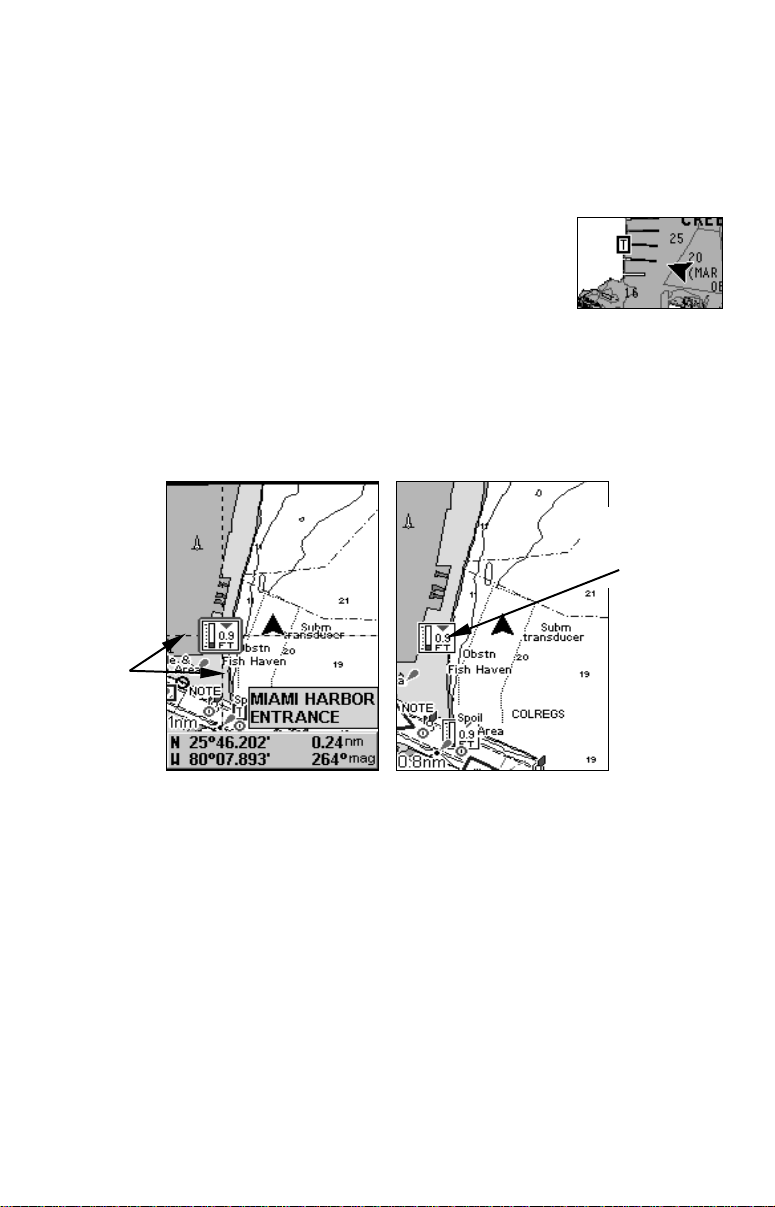
To select another date:
1. Use ← → to highlight month, day or year, then press
2. Use ↑ ↓ to select the desired month, day or year and press
To clear the information screen, press
EXIT.
ENT.
ENT.
Tide Information
NauticPath charts contain Tidal Information,
represented at large zoom ranges by a box icon with
the letter "T." These icons will appear when you are
zoomed in to a 6-mile range. The icon stands for a
Tidal Station location. An example is displayed at right.
When you zoom in to a sufficiently small zoom range (0.8 nautical
mile), the icon becomes an animated gauge showing a rising or falling
tidal height for the selected station at the present time. At larger zoom
ranges, you can select the boxed "T" icon and it becomes an animated
gauge with a pop-up name box. The name box disappears seconds.
Tide Station
icon in animated mode
Cursor
lines
NauticPath chart showing Tide Station icon selected by cursor (left).
Icon animates automatically without selection at the 0.8-mile zoom
range (right). In the example above, the tide is at 0.9 feet and falling,
as shown by the down arrow at the top of the icon.
To view tide information:
1. Use the arrow keys to move the cursor over a tide station icon. When
it is selected, a pop-up name box appears.
2. Press
WPT to display the Tide Information screen.
84
Page 91

Current Time Line
Height
MLLW
Line
Tide
Table
Tide Information screen.
Scale
The Tide Information screen displays daily tidal data for this station on
this date at the present time. The graph at the top of the screen is an
approximate view of the tidal range pattern for the day, from midnight
(MN) to noon (NN) to midnight (MN). The dotted line across the graph
is the Mean Lower Low Water line (MLLW).
The height scale on the top right side of the graph changes, based upon
the maximum range of the tide for that day. The MLLW line also ad-
justs its position as the height scale changes.
You can look up tidal data for other dates by changing the month, day
and year selection boxes. To select another date:
1. Use ← → to highlight month, day or year, then press
2. Use ↑ ↓ to select the desired month, day or year and press
To clear the information screen, press
EXIT.
ENT.
ENT.
Navionics Charts
Your unit can also display Navionics electronic charts on MMCs. Like
NauticPath, Navionics charts contain tide and port service information.
NOTE:
The primary operational difference between a NauticPath chart
and a Navionics chart is the way the chart data is set up for display. NauticPath charts are ready for display as soon as they are
inserted into the unit. Navionics charts must be inserted into the
unit, then selected as a Map Choice option in the Map Data menu.
To display a Navionics chart:
1. Install the Navionics MMC in the memory card compartment and
turn on the unit. (For full card install instructions, see Sec. 2.)
85
Page 92

2. From the Map Page, press
CHOICE|ENT. Select the Map Name, then press ENT|EXIT|EXIT.
MENU|↓ to MAP DATA|ENT|↓ to MAP
WARNING:
You should never format the MMC containing your
Navionics chart. Formatting the MMC will permanently
erase the chart from the card.
Overlay Data
On any Page display except Satellite Status, you can float or overlay
additional GPS or navigation data on the screen with the Overlay Data
command. For example, if you left your watch at home, you could display the local time on top of the map. Or if you wanted to see details
about your route and trip, you could show your bearing, course, average
speed and trip distance.
Overlay Data menu with Press Ent to add highlighted (left). Data viewer
with GPS Data category opened (center). Ground Speed is turned on
(checked). Both GPS Data and Trip Calculator categories are opened
(right) with Ground Speed, Position and Trip Time turned on.
To overlay information on your screen:
1. While on the Map Page, press
2. Select
ENT TO ADD and press ENT. The Data Viewer menu will appear.
MENU|↓ to OVERLAY DATA|ENT.
It has four categories: GPS Data, Navigation, Trip Calculator and
Time. If the desired category is flanked by a "+", a list of data options
will appear when you highlight the category and press
ENT. After
opening a category it will have a "–" next to it. To close the category,
highlight it and press
ENT.
3. Open the desired category and use ↑ ↓ to select the desired overlay
data option and press
ENT to turn it on (check) or turn it off (uncheck).
Use ↑ ↓ to select another overlay data option for display or press
EXIT|EXIT to return to normal operation..
86
Page 93
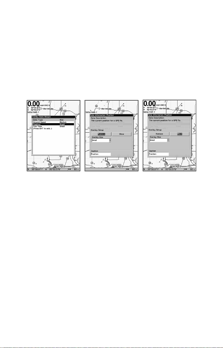
Every Page display has a maximum number of items you can show using the Overlay Data command.
To remove overlaid data:
1. While on the Page that shows the data you want to remove, press
MENU|↓ to OVERLAY DATA|ENT.
2. You will see a list of the overlay data currently displayed. Select the
item you want to remove from the display and press
ENT|ENT to re-
move the data. To remove another item, repeat Step 2.
3. When you have finished removing all the items you want from the
screen, press
Overlay Data Shown menu with position data option selected (left).
Data information window with Remove highlighted (center). Move is
EXIT to return to the main page display.
highlighted on Data information window (right).
To move overlaid data:
You may find it useful to move data floating on your display.
1. From one of the Map Pages, press
MENU|↓ to OVERLAY DATA|ENT.
2. You will see a list of the overlay data currently displayed. Select the
item you want to move and press
ENT|→ to MOVE|ENT.
3. The data begins to flash on your screen. Use ↓ ↑, ← → to move the
data to a new location on the display.
4. When have the data in the desired position, press
EXIT|EXIT.
NOTE:
The Customize and Overlay Data commands use the same information categories. The difference between the two commands is Customize changes only the data in digital data boxes, while Overlay
Data changes information floating on the screen.
87
Page 94

To change displayed data font size:
arrow
1. From the Map page, press MENU|↓ to OVERLAY DATA|ENT.
2. Press ↓ ↑ to select a data type to resize, then press ← → scroll
through five data size options: Off, Small, Medium, Large and Enormous. Press
EXIT. The selected data type will be displayed in the new
size.
Steering
Map Page showing Ground Speed, Trip Time and the Steering Arrow.
NOTE:
Some data types can be displayed in only one font size. If that is the
case, the Data Size box will not be displayed for that data type.
Pop-up Help
Help is available for most all menu items on this unit. By highlighting
a menu item and leaving it highlighted for a few seconds, a pop-up
message appears that describes the function of the menu item. This
feature is on by default.
To turn on Popup Help press
to
POPUP HELP. Press ENT to turn it on (check) or turn it off (uncheck).
Press
EXIT repeatedly to get back to the main page display.
MENU|MENU|↓ to SYSTEM SETUP|ENT|↓
88
Page 95

System Setup Menu (left) with Pop-up Help highlighted.
Pop-up Help message for the Map Data (right).
Reset Options
To reset unit to factory defaults:
1. Press
to
NOTE:
MENU|MENU|↓ to SYSTEM SETUP|ENT|↓ to RESET OPTIONS|ENT|←
YES|ENT.
Reset Options does not erase any waypoints, routes, icons or plot trails.
System Menu with Reset Options selected (left).
Reset Options confirmation message (right).
Require WAAS
You can choose to have WAAS signals automatically factored into every
position reading. The default setting, Off, uses WAAS automatically,
but does not require it to yield a position.
89
Page 96

To Require WAAS:
1. Press
2. To return to the main page display, press
MENU|MENU|↓ to GPS SETUP|ENT|↓ to REQUIRE WAAS|ENT.
EXIT|EXIT.
3. Repeat Step 1 to turn off WAAS requirement.
Require WAAS command on GPS Setup Menu.
Screen Contrast and Brightness
To access the Screen menu, press MENU|MENU|ENT.
The
CONTRAST slider bar is already selected. Press ← → to adjust the
contrast.
To adjust the display's brightness:
Press ↓ to
BRIGHTNESS. Use ← → to adjust the brightness of the display.
Screen Command (left). Screen menu with Contrast selected (center).
Normal highlighted on Display Mode menu (right).
To adjust the screen's display mode:
Press ↓ to
DISPLAY MODE|ENT. Press ↑ ↓ to select mode|EXIT.
90
Page 97

Set Language
This unit's menus are available in 10 languages: English, French, German, Spanish, Italian, Danish, Swedish, Russian, Dutch and Finnish.
To select a different language:
1. Press
2. Press ↓ to
3. Use ↓ ↑ to select a different language and press
MENU|MENU|↓ to SYSTEM SETUP|ENT.
SET LANGUAGE|ENT.
ENT. Menus now ap-
pear in the language you selected.
Set Local Time
To access the Set Local Time menu, you must first acquire your position, then press
TIME|ENT.
To set Local Time: Press
then press → to move the cursor to the next character. Repeat until the
time is correct and press
To set the Month: Press ↓ to
and press
ENT.
To set the Day: Press ↓ → to
press
ENT.
To set the Year: Press ↓ → to
and press
ENT.
To set Time Format: Press ↓ to
press
ENT to turn it on or off.
To set Date Format: Press ↓ → to
and press
ENT to turn it on or off.
The last field in this menu is CONFIG DST. This feature sets up the unit
to automatically adjust with the time change resulting from Daylight
Saving Time. You may select which set of rules matches DST in your
region or just accept the default. You should only have to configure DST
once.
Once you have each field set the way you want, press
get back to the main page display.
MENU|MENU|↓ to SYSTEM SETUP|ENT|↓ to SET LOCAL
ENT. Use ↑ ↓ to change the first character,
ENT.
MONTH|ENT. Use ↑ ↓ to select the month
DAY|ENT. Press ↑ ↓ to select the day and
YEAR|ENT. Press ↑ ↓ to select the year
TIME FORMAT, highlight an option and
DATE FORMAT, highlight an option
EXIT repeatedly to
Show WAAS Alarm
When the signal is available, your unit will automatically use WAAS to
boost the accuracy of a position fix. When the WAAS signal is lost or
acquired, a message appears. Since the U.S. government is still developing the WAAS system, it is not unusual for a GPS/WAAS receiver to
91
Page 98

frequently lose and reacquire its lock on a WAAS satellite. That can
result in the alarm repeatedly going off. If you want, turn off the WAAS
Acquired/Lost alarm without affecting how the unit uses WAAS.
To turn off WAAS alarm:
1. Press
2. Press
tion is set, press
MENU|MENU|↓ to GPS SETUP|ENT|↓ to SHOW WAAS ALARM.
ENT to turn it on (check) or turn it off (uncheck). After the op-
EXIT|EXIT to return to the page display.
3. To turn the alarm on again, repeat Steps 1 and 2.
Software Version Information
From time to time, Eagle updates the operating system software in
some of its products. These software upgrades usually are offered to
customers as free downloads from our web site, www.eaglegps.com. The
upgrades make the unit perform better or introduce new features and
functions. Use the software information command to see what software
version is running in your unit.
Main Menu with Software Information selected (left).
The Software Information screen (right).
Press MENU|MENU|↓ to SYSTEM SETUP|ENT|↓ to SOFTWARE
INFORMATION|ENT. To return to the page display, press EXIT repeatedly.
Sounds Menu
To adjust Sounds and Alarm Styles:
Press
MENU|MENU|↓ to SOUNDS|ENT.
To set Key Press Sounds: Press
them off (uncheck).
To set Alarm Sounds: Press ↓ to
lighted, press
ENT to turn them on (check) or turn them off (uncheck).
ENT to turn them on (check) or turn
ALARM SOUNDS. With the option high-
92
Page 99

To set Volume: Press ↓ to
To set Alarm Style: Press ↓ to
the style and press ENT. After the option is set, press EXIT|EXIT to return to the main page display.
Sounds highlighted on main menu (left). Sounds menu (right).
VOLUME. Use ← → to adjust the volume.
ALARM STYLE|ENT. Press ↑ ↓ to change
Track Smoothing
This is a factory setting on the GPS Setup menu that should always be
on. When stopped or traveling at slow speeds, like walking or trolling,
Track Smoothing prevents trails from wandering. It benefits the steering arrow, compass rose and map in track-up mode in the same manner.
Track Smoothing option, turned on.
Trail Options
There are several options you can use with trails. Some affect all trails,
others can be applied to a particular trail. You can change the way
trails are updated, display or hide trails, create a new trail, delete a
trail, etc.
93
Page 100

Main Menu (left). Trails Menu (center). Trail Options (right).
General Trail Options
To access the Trails Menu press MENU|MENU|↓ to MY TRAILS|ENT.
Delete All Trails
From the Trails Menu, press → to
DELETE ALL|ENT|← to YES|ENT.
Update Trail Option
This menu lets you change the way the trail updates occur.
From the Trails Menu, press → to
TRAIL highlighted, press ENT to turn it on (check) or turn it off (uncheck).
TRAIL OPTIONS|ENT. With UPDATE ACTIVE
WARNING:
If you uncheck the Update Trail option, automatic trail
creation and recording will be turned off. You must turn
it on to record trails. The default setting is on.
Update Trail Criteria
The options are automatic, time or distance. When it is in the default
mode, the unit does not update the plot trail while you are traveling in
a straight line. Once you deviate from a straight line, the unit drops a
plot point onto the trail. This conserves plot trail points. If a plot trail
uses all the available points allotted to it, the beginning points are
taken away and placed at the end of the trail.
From the Trails Menu, press → to
Update Criteria options — Auto, Time or Distance — and press
OPTIONS|ENT. Select one of the three
ENT.
Trail Update Rate
A trail updated by time has a range of 1 to 9999 seconds. The default is
3 seconds. The range for updating a trail by distance is 0.01
mile/nm/km to 9.99 mile/nm/km. The default is 0.10 mi.
When time or distance are chosen as the update criteria for a trail, a
dialog box will appear, allowing you to input the desired update rate or
distance. Select the dialog box and press
ENT. Use ↑ ↓ to change the
94
 Loading...