

Page 1

LP4300 FLOOR SCALE
OPERATION INSTALLATION AND SERVICE MANUAL
366 CIRCLE OF PROGRESS POTTSTOWN, PA 19464
(610)323-2250 FAX: (610)323-0114
Page 2

TABLE OF CONTENTS
CONTENTS
SECTION 1.0 DESCRIPTION.
SECTION 2.0 PREPARATION FOR USE
SECTION 2.1 RECEIVING INSPECTION
SECTION 2.2 SHIPMENT
SECTION 2.3 SITE SELECTION
SECTION 2.4 INSTALLING
SECTION 2.5 LEVELING
SECTION 2.6 HOOK-UP CABLE
SECTION 3.0 TROUBLE SHOOTING
SECTION 4.0 SERVICING
SECTION 4.1 CHECKING THE CONNECTIONS
SECTION 4.2 SERVICING THE LOAD CELL
SECTION 4.3 CHECKING THE LOAD CELL
SECTION 4.4 REPLACING THE LOAD CELL
SECTION 5.0 SPECIFICATIONS
SECTION 6.0 SPARE PARTS LIST
LIST OF ILLUSTRATIONS
FIGURE 1 HOOK-UP CABLE TABLE
FIGURE 1 SUMMING BOARD CONNECTIONS
FIGURE 3 RESISTANCE TABLE
FIGURE 4 OUTPUT TABLE
Page 3
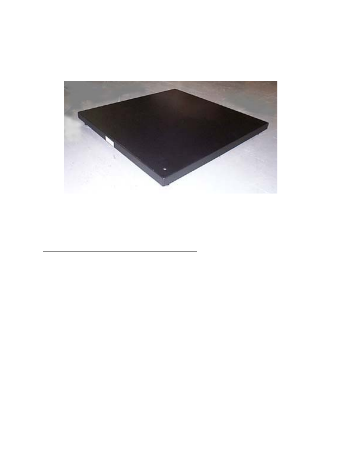
SECTION 1.0 DESCRIPTION
The Eagle Microsystems Model LP4300 is a low profile industrial floor scale available in four sizes; 30" x
30", 36" x 36", 42" x 42" and 48" x 48".
The LP4300 was designed for easy installation and maintenance. All maintenance and calibration work is
performed from the top surface and does not require the removal of any decking or lifting the scale to
adjust the leveling. The load cell summing board is located in a drawer on the side of the scale.
SECTION 2.0 PREPARAT ION FOR USE
2.1 RECEIVING INSPECTION
1. Upon receiving the scale, carefully inspect the condition of the crate including the banding
and any protective covering used for shipping. Report any damage to the shipper and to
Eagle Microsystems.
2. Remove the scale from crating and inspect for damage. Report any damage to the shipper
and to Eagle Microsystems.
3. The scale is shipped with the four (4) leveling feet removed. The feet are packaged and strapped
to the cable. Keep these with the scale untill instllation time.
2.2 SHIPMENT
Should re-shipment of your scale become necessary.
1. Use a strong, well built crate. The crate must be larger than the outer dimensions of the
scale to protect it in shipping.
2. Make sure the hook-up cable is protected and secured in crate.
3. Use strong banding to secure scale in shipment.
Page 4

2.3SITE SELECTION
1. Line power devices causing large inductive currents should not run off the same circuit as
the scale. Fluctuations in line voltage caused by such devices may result in display instability.
2. The hook-up cable to the read-out should not run close to other unshielded cables. Display
instability may result.
3. For best accuracy, a flat, level, and rigid surface is recommended to support the scale and ton
containers.
4. The area should be accessible for periodic cleaning.
2.4INSTALLING
1. Clean the site area of dirt and debris.
2. With the bottom of the scale exposed, install the four leveling feet in the four corners of the scale.
2.5 LEVELING
Corner detail showing easy leveling adjustments
with scale in place. A screw driver is the only tool needed.
1. For best scale performance scale should be level within 1/2 degree.
2. Check all corners for wobble and adjust leveling feet as if required, with a sctew driver through the
acess holes. (see photo)
.
2.6 HOOK-UP CABLE
Figure 1 shows the wiring connections necessary to attach the platform to the read-out instrument. The
color code and function are as noted.
COLOR FUNCTION
BLACK – EXCITATION
WHITE – SIGNAL
RED + EXCITATION
GREEN + SIGNAL
Fig. 1
Page 5

SECTION 3.0 TROUBLE SHOOTING
The following is a list of potential problems and likely cures.
1. Inaccurate but repeatable weight readings:
a. Adjust span on read-out (see instrument manual)
2. Blank or drifting display:
a. Consult the instrument manual.
b. Look for loose connection in hook-up cable at the instrument or in the Summing Box.
See Section 4.0
d. Look for moisture in the Summing Box
c. Test for bad load cell (see section 4.2)
SECTION 4.0 SERVICING
4.1 Checking the connections to the Summing Box.
1. Locate the Summing J Box under the scale and remove the lid.
2. View and compare all connections to Figure 2.
3. Check all connections by lightly pulling on each lead. Tighten terminal connections as
needed.
4. If problem persists, press lightly on the circuit board itself and check meter response.
Replace board if required.
Note: Make sure when replacing the cover that the box is dry and the cover is tight.
SJB4-S
+E
+E
-E
-S
+S
-E
+S
R1 R1
SH
-S
SH
R1
-
+
-SIG
-EXT
+EXCT
EAGLE MICROSYSTEMS
+SIG
R1R1
SHLD
+E
+E
-E
-S
+S
-E
-S
+S
Figure 2
SH
SH
Page 6

4.2 Checking the load cells.
1. Load Cell resistance test:
a. Disconnect the load cells from the Summing Box and measure the resistance as shown in
Figure 3.
b. Any electrical leakage between the leads and the load cell case is usually caused by moisture
leakage into the load cell or by moisture in a damaged load cell cable.
c. If a load cell does not pass the above resistance tests, replace it with a known good one.
LOAD CELL WIRING
LOAD
CELL
LOAD CELL RESISTANCE CHECK
RED TO BLACK 360
GREEN TO WHITE 350 +/- 5
RED, BLACK, GREEN,
WHITE, OR YELLOW
TO CASE
* Using a portable Ohm meter on highest range you should read infinity
2. Load Cell zero shift test:
a. Remove all the weight from the load cell and measure the output as shown in
Figure 4.
b. Connect a DC power supply of 10 or 15 volts to the Red (+) and Black (-) excitation load cell
leads.
RED +EXT
BLK -EXT
GRN +SIG
WHT -SIG
YEL SHLD
Ω
Ω
GREATER THAN 200
MEGOHMS *
FIGURE 3
c. The measured output between the Green (+) and White (-) signal leads should be less
than 5 millivolts.
d. An output signal greater than 5 millivolts indicates a zero shift caused by mechanical
overload.
e. If the output signal is between 5 and 15 millivolts, the load cells zero has shifted but will
probably still continue to work.
f. If the output signal is greater than 15 millivolts, the load cell should be replaced with a
known good one.
Page 7

LOAD CELL WIRING
RED +EXT
LOAD
CELL
LOAD CELL VOLTAGE CHECK (WITH 15V EXCITATION)
BLACK TO WHITE: +7.5V (EXCITATION / 2)
BLACK TO GREEN: +7.5V (EXCITATION / 2)
BLACK TO RED: +15V
LOAD CELL OUTPUT
GREEN TO WHITE: LESS THEN +/- 5 MILLIVOLTS (NO DEAD LOAD)
LESS THEN 25 MILLIVOLTS (EXACT OUTPUT
VOLTAGE DEPENDS ON DEAD LOAD WEIGHT)
NOTE: If the load cell's zero has shifted due to a mechanical overload, the reason for the
overload should be determined before a new load cell is installed.
4.3 REPLACING THE LOAD CELL
BLK -EXT
GRN +SIG
WHT -SIG
YEL SHLD
FIGURE 4
Call the factory to advise that the load cell is defective. Report model and serial numbers for both load cell
and scale.
1. Remove all weight from scale.
2. Stand the scale on its side. Use caution; make sure that the hook-up cable is not being damaged.
3. Remove the screws from Summing Box lid. Disconnect the wires of defective load cell
being replaced. Gently pull cable out of the frame.
4. Use 3/4 wrench to remove 2 hext head cap screws which secure load cell to frame.
5. Install new load cell using 35 ft. lbs. torque to screws and fish wires back to the Summing Box.
6. Insert leads into terminal as before and tighten. Put lid on Summing Box and tighten.
7. With a screw driver, adjust the leveling foot until scale is stable on all four feet.
Page 8

SECTION 5.0 SPECIFICATIONS
PHYSICAL SIZE: Model LP4300
30" x 30", 36" x 36", 42" x 42", and 48" x 48".
WEIGHT: 33" x30" = 96 lbs, 36" x 36" = 115 lbs
42" x 42" = 135 lbs, 48" x 48" = 162 lbs
CONSTRUCTION: Welded steel and formed plate.
FINISH: Primer and acrylic paint
CAPACITY: 1000, 2000 and 5000 LB cap.
SAFE OVERLOAD: 200% of Rated Capacity.
ULTIMATE OVERLOAD: 400% of Rated Capacity.
NOMINAL OUTPUT: 1.5 mV/V at full scale
OPERATING ACCURACY: 0.1% of Capacity.
REPEATABILITY: 0.02% of Capacity.
LOAD CELLS: 4 stainless steel strain gage beams, 350 Ω.
HOOK-UP CABLE: 15' of 6 conductor color coded shielded cable. PVC jacket.
SECTION 6.0 SPARE PARTS LIST
PART DESCRIPTION MODEL/CAPACITY
S.S. Load Cell 1,000 lbs F.S.
S.S. Load Cell 3,000 lbs F.S.
S.S. Load Cell 5,000 lbs F.S.
S.S. 1/2-20 live footAll sizes and capacities
As Req'd 6 Conductor Cable 15' Standard
Load cell Summing Board SJB-4-SAll sizes and capacities
 Loading...