

Page 1

E15 SPRAYER Operators Manual
KEE E15 Horticultural Sprayer Console
W117 V1.0
Page 2

V 3.0 100903
Major Topic Heading
How to use this operator’s manual
As with any computer operated equipment, software and/or hardware is in many cases changed
and upgraded over the life of the equipment.
KEE Technologies software engineers are constantly working on software enhancements which
will provide you with many additional benefits and features in the future.
The EAGLE System will keep on evolving! ...to ultimately improve your ‘bottom line”!
KEE Technologies personnel have records of all changes implemented to your system with the
subsequent serial number.
When talking to KEE Technologies Support staff, always have this manual with you, as we may
ask you what version manual you are currently looking at to ensure we all talk the same
language. For this purpose all pages are coded as follows.
Page number Date when written Software version
Below is space provided to keep records of any software and hardware upgrades you may have
received.
The Software Version Number of the Eagle Console can be located when the console first powers
up. The File name which contains the Software version number will be displayed for about 2-3
seconds.
The name of the file will be on the last line, it will look like this.
KEE_HSC_1_0_13.HEX
Where: KEE_HSC_ -shows the type of software, is a KEE Horticultural Sprayer Complete.
1_0_13 - The software version number
HEX - Type of file.
Type of upgrade (software or hardware) Version Date Manual upgraded
KEE Eagle E15 Horticultural Sprayer
1.0.13 11/05
11/05
Page 3

V1.86
V 1.86
3.0 SPRAYER SETUP MENU
19
3.1 SET THE PRESET RATE 1 20
3.2 SET THE PRESET RATE 2 20
3.3 MINIMUM FLOW HOLD 20
3.4 SET THE PRESET ROW WIDTH AND SECTIONS WIDTHS 21
3.5 SET THE LOW SPEED SHUT OFF 23
3.6 SET THE TANK VOLUME 23
3.7 APPLICATION MODE 23
3.8 SET THE WHEEL CALIBRATION FACTOR 24
3.8.1 SELECT SPEED SOURCE 25
3.8.2 AUTOMATIC WHEEL CALIBRATION 25
3.8.3 MANUAL ENTRY OF WHEEL FACTOR 25
3.9 SET THE FLOW CALIBRATION FACTOR 26
3.9.1 AUTOMATIC FLOW CALIBRATION 27
3.9.2 MANUAL FLOW CALIBRATION 27
3.10 SPRAYER SETUP 2 MENU 28
3.11 SET A MANUAL SPEED 29
3.12 SET RATE INCREMENT 29
3.13 SET NUMBER OF BOOM SECTIONS 29
3.14 ENABLE DATA LOGGER 30
3.15 ENABLE FLUSH OUTPUT 30
3.16 SET FLUSH TIME 30
3.17 ENABLE FULL ROW PER SECTION 31
3.18 ENABLE AUXILIARY FUNCTION 31
3.19 SPRAYER SETUP 3 MENU 32
3.20 ENABLE PUMP SPEED SENSOR 33
3.21 ENABLE AUXILIARY SHAFT SENSOR 33
3.22 ENABLE DUMP OVERRIDE 33
3.23 SELECT DUMP MODE 34
3.24 SET THE VALVE TYPE 34
3.25 SET THE CONSOLE UNITS 34
3.26 ENABLE FAN MONITORING 35
3.27 SET NUMBER OF FANS 35
3.28 SPRAYER SETUP 4 MENU 36
3.29 ENABLE PRESSURE1 SENSOR 37
3.30 SETTING THE PRESSURE GAIN 37
3.31 SETTING THE TYPE OF PRESSURE SENSOR 37
3.32 PRESSURE SENSOR 1 CALIBRATION 38
Content Page No.
Table of Contents
1.0 MENU OVERVIEW 11
2.0 CONSOLE OVERVIEW 12
2.1 WORKING SCREEN DISPLAY 12
2.2 WORKING SCREEN BUTTON FUNCTIONS 14
2.3 MAIN MENU 17
2.4 SETUP MENU 18
3
V 1.0 11/05
Page 4

4. ALARMS SETUP MENU 40
4.1 RATE ALARMS 41
4.1.1 ENABLE THE MINIMUM FLOW ALARM 42
4.1.2 ENABLE THE APPLICATION RATE LOW ALARM 42
4.1.3 SET THE APPLICATION RATE LOW POINT 42
4.1.4 ENABLE THE APPLICATION RATE HIGH ALARM 43
4.1.5 SET THE APPLICATION RATE HIGH POINT 43
4.2 SHAFT ALARMS 44
4.2.1 ENABLE THE PUMP SPEED LOW ALARM 45
4.2.2 SET THE PUMP SPEED LOW ALARM POINT 45
4.2.3 ENABLE THE PUMP SPEED HIGH ALARM 45
4.2.4 SET THE PUMP SPEED HIGH POINT 46
4.2.5 ENABLE THE AUXILIARY SHAFT LOW ALARM 46
4.2.6 SET THE AUXILIARY SHAFT LOW ALARM POINT 46
4.2.7 ENABLE THE AUXILIARY SHAFT HIGH ALARM 47
4.2.8 SET THE AUXILIARY SHAFT ALARM HIGH POINT 47
4.3 SPEED ALARMS 48
4.3.1 ENABLE THE SPEED LOW ALARM 49
4.3.2 SET THE SPEED LOW ALARM POINT 49
4.3.3 ENABLE THE SPEED HIGH ALARM 49
4.3.4 SET THE SPEED HIGH ALARM POINT 50
4.4 TANK ALARMS 51
4.4.1 ENABLE THE VOLUME LOW ALARM 52
4.4.2 SET THE VOLUME LOW POINT 52
4.5 PRESSURE ALARMS 53
4.5.1 ENABLE THE PRESSURE 1 LOW ALARM 54
4.5.2 SET THE PRESSURE 1 LOW ALARM POINT 54
4.5.3 ENABLE THE PRESSURE 1 HIGH ALARM 54
4.5.4 SET THE PRESSURE 1 HIGH ALARM POINT 55
Table of Contents
Content Page No.
6. OPERATING HISTORY 60
6.1 TOTALS HISTORY 61
6.1.1 RESET THE TOTAL VOLUME 62
6.1.2 RESET THE SUB VOLUME 62
6.1.3 RESET THE TOTAL AREA 62
6.1.4 RESET THE SUB AREA 62
6.1.5 RESET THE TOTAL DISTANCE 63
6.1.6 RESET THE SUB DISTANCE 63
6.1.7 RESET THE TOTAL TIME 63
6.1.8 CHANGE TO A DIFFERENT SUB AREA 63
6.2 SHAFT SPEED HISTORY 64
6.3 MACHINE HISTORY 65
4
5. CONTROLLER SETUP MENU 56
5.1 SET CONTROL MODE 57
5.2 SET THE MAX ON TIME 57
5.3 SET THE MIN ON TIME 57
5.4 SET THE GAIN SETTING 58
5.5 SET THE PWM SETTING 58
5.6 SET THE FLOW METER SENSITIVITY 58
5.7 SELECT CLOSE VALVE WHEN OFF 59
5.8 TOGGLE THE VALVE REVERSE 59
V 1.0 11/05
Page 5

7. OPERATIONS: SPRAYER 66
7.1 OPERATION OF THE SPRAYER 67
7.1.1 DISPLAY THE VOLUME REMAINING IN THE TANK 67
7.1.2 DISPLAY THE VOLUME USED 67
7.1.3 FILL THE TANK 67
7.1.4 FILL THE TANK TO A SET VOLUME 67
7.1.5 TO DISPLAY SUB AREA, TOTAL AREA AND SUB AREA NUMBER 67
7.1.6 TURN A SECTION ON 67
7.1.7 TO CLEAR A SUB AREA 68
7.1.8 TO CHANGE THE SUB AREA NUMBER 68
7.1.9 RESET TOTAL AREA 68
7.1.10 SELECT BETWEEN MANUAL AND AUTO SPRAYING 68
7.1.11 SELECT BETWEEN COVERAGE RATE, ROW WIDTH, PRESSURE1,
& FAN SPEED1 69
7.1.12 SELECT BETWEEN FLOW RATE,PUMP SPEED,AUX SHAFT SPEED
& FAN SPEED 69
7.1.13 SELECT BETWEEN VOLUME LEFT AND FLUSH FUNCTION 70
7.1.14 SELECT BETWEEN VOLUME USED, AUX FUNCTION, DUMP OVERRIDE
& DATA 70
7.1.15 SELECT ROW WIDTH 70
7.1.16 ACTIVATE FLUSH FUNCTION 71
7.1.17 ACTIVATE DUMP OVERRIDE FUNCTION 71
7.1.18 ACTIVATE AUXILIARY FUNCTION 72
7.1.19 DISPLAY FAN SPEED MONITORING SCREEN 72
7.2 TO BEGIN SPRAYING 73
7.2.1 TO BEGIN SPRAYING (MANUAL MODE) 73
7.2.2 INCREASE OR DECREASE the APPLICATION RATE (MANUAL MODE) 73
7.2.3 BEGIN SPRAYING (AUTO MODE) 73
7.2.4 CHOOSE A PRESET APPLICATION RATE (AUTO MODE) 73
7.2.5 INCREASE OR DECREASE the APPLICATION RATE (AUTO MODE) 73
7.3 OPERATIONS: DATA LOGGER 74
7.3.1 CONNECT THE DATA LOGGER INTERFACE TO THE EAGLE E15H 75
7.3.2 CONNECT A MODULE TO THE DATA LOGGER INTERFACE 75
7.3.3 REMOVE A MODULE FROM THE DATA LOGGER INTERFACE 75
7.3.4 SPRAY TO A PROGRAMMED RATE 75
7.3.5 CHANGE THE JOB NUMBER 76
7.3.6 SPRAY WITHOUT USING PROGRAMMED RATE 76
Table of Contents
Content Page No.
5
V 1.0 11/05
Page 6

8.0. CONFIGURATION OPTIONS 77
8.1 KEY CONFIGURATION 78
8.1.1 ENABLE THE KEY BEEPER ON OR OFF 79
8.1.2 SET THE KEY BEEPER TIME 79
8.1.3 ENABLE THE KEY REPEAT 79
8.1.4 SET THE KEY REPEAT DURATION 79
8.2 ALARM CONFIGURATION 80
8.2.1 ALARM BEEPER OVERVIEW 81
8.2.2 SET THE ALARM CYCLE TIME 82
8.2.3 SET THE ALARM DUTY CYCLE 82
8.2.4 SET THE NUMBER OF ALARM CYCLES 82
8.2.5 ENABLE THE ALARM BEEPER ON/OFF 82
8.3 GENERAL CONFIGURATION 83
8.3.1 COLD RESET 83
8.3.2 FACTORY RESET 83
8.4 SWITCH CONFIGURATION 84
Table of Contents
Content Page No.
9.0. DIAGNOSTICS MODE 85
9.1 LED TEST 86
9.2 SWITCH TEST 87
9.3 KEYS TEST 88
9.4 SENSORS TEST 89
9.4.1 CHECKING LOOM VOLTAGES, FOR 3 PIN SENSORS 90
9.5 RELAYS TEST 91
9.6 REGULATOR VALVE TEST 92
9.7 EEPROM TEST 93
9.8 DISPLAY TEST 93
10. ALARM MESSAGES 94
10.1 ALARM MESSAGES OVERVIEW 94
10.2 ALARM MESSAGES 95
11. SPECIFICATIONS 98
12. WIRING DIAGRAMS
12.1 ECONOMY LOOMS 100
EAGLE CONSOLE PIN OUTS 100
TRACTOR LOOM 101
TRACTOR LOOM 102
SPRAYER LOOM 103
MK5 TO E15h ADAPTOR LOOM 104
6
V 1.0 11/05
Page 7

E15h SPRAYER
Features of the E15h EAGLE HORTICULTURAL SPRAYER CONSOLE:
• 4 Preset Widths can be entered.
• 4 Row Section switches can control (solenoid, 2 or 3 wire Valves)
• Sprayer can be setup as a:
2 section sprayer
3 section sprayer (2 left and 1 right)
3 section sprayer (2 right and 1 left)
OR 4 section sprayer
• The Sprayer can be setup to switch
1/2 a row per section switch
OR switch a Full row per section switch.
• Auxiliary Function to operate ‘Work Lights’ or ‘Foam Marker’
• Displays PTO SHAFT in rpm, with alarms points. Also display readouts and alarms
which are settable for an Auxiliary Shaft sensor.
• Displays and Monitors up to 12 Fans.
• The KEE Data Logger can be connected to the E15h console to create and
recored all spray jobs.
• Automatic Dump and Flush Functions
• Master ON/OFF switch
• 2 Dedicated Rate buttons (RATE 1/ RATE 2) ; gives the operator finger-tip control
• Rate can be displayed in volume/area (eg. L/Ha) OR volume/distance (eg. L/100m)
• Can control different types of Flow Control (Servo) Valves
• Audio and Visual alarms; low and high alarm points settable for each alarm
• Large Full Visual display
• Displays 8 functions at once; Ground Speed, Rate, Sub-Area, Coverage Rate,
Volume Left, Volume Used, Flow Rate and current alarms ALL on the one screen
• Selectable units (Gallons/Acre, Litres/Hectare etc)
• Machine history data
• Self diagnosis tests
• Back lit keys, with separate contrast knob for full screen control
• 10 Sub Areas keeps records on Hectares sprayed and Volume Used
• Easily Setup and Simple to use
7
V 1.0 11/05
Page 8

E15h SPRAYER
The EAGLE E15 Sprayer Console replaces the KEE Technologies Mk3 and Mk5 Spray
Controllers, which have been in the market for the past 25 years. The EAGLE is a
breakthrough replacement for the Mk5, with many more features at no extra cost. It
takes into account the current Mk5 operators, and the transition from the Mk5 to the
EAGLE is minimal, to the point where it is fully compatible with all Mk5 hardware. It is as
simple as swapping the consoles!
The development of the EAGLE has been totally driven by input and suggestions from
farmers and contractors from around the world, making the EAGLE the most advanced
Spray Rate Controller in the world.
The KEE Eagle Horticultural console is a dedicated horticultural sprayer console
developed specifically for the horticultural market.
The Eagle has many new features and easy operation, that has leap-frogged the current
competition which is a considerable bonus to the end user. Including all the features of
its predecessor, the MK5, the EAGLE has four sections, separately indicated section
switches, can display in volume/area or volume/distance, can connect to 2 section, 3
section (3L or 3R) and 4 section sprayers.
The E15h console can monitor 1 to 2 fans. If the optional FAN MONITOR ECU is used
then up to 12 Fans can be monitored and each Fans RPM can be displayed.
The Data Logger (optional) can be connected to the E15h console to set the application
rate for up to 9 jobs and create job sheets for each job; then the Data Logger will record
application rate, which sections where switched ON/OFF, pressure, speed etc to a
Module. The Module can be taken back to the office and create records of jobs done;
graphs can then be created using the Data Logger software.
New features include the all screen display that allows viewing of all the sprayer
functions at a glance, backlight control keys and positive sectional switches.
8
V 1.0 11/05
Page 9

Major Topic Heading
V 1.2
Personal Notes
9
Page 10

Major Topic Heading
V 1.2
Major Topic Heading
V 1.2
Personal Notes
10
Page 11

E15h SPRAYER- Console Overview
1.0 MENU OVERVIEW
1.1 TO MOVE THE FOCUS AROUND THE SCREEN
• The buttons along the left hand side (LINE 1, LINE 2, LINE 3 AND LINE 4) of the
screen are aligned with a row on the screen.
• Pressing a left hand button will hightlight the first focus square on that row
• If there is no text on a row, you will not be able to set the focus to that row
• If a value is uneditable (ie a title or display value) you may not be able to set the
focus to that state.
• To move between windows on a single row, press the corresponding (LINE 1,
LINE 2,LINE 3 or LINE 4) button repeatedly. The focus will switch between available
fields on the row.
1.2 TO ENTER THE MENU FROM THE WORKING SCREEN
• Ensure the Master Switch is in the OFF (hold) position
• Press the MENU button
• You will be taken to the MAIN MENU screen
1.3 TO RETURN TO THE WORKING SCREEN
• Ensure that you are not editing a value (if you are editing a value an asterisk (*)
will be shown in the box the focus is set to)
• Press the MENU key
• You will be returned to the previous menu screen
1.4 TO ENTER A MENU SCREEN
• Highlight the field displaying the menu you wish to enter
• Press the ENTER key
• You will be taken to the corresponding menu
1.5 TO EDIT A VALUE
• Highlight the field displaying the value you wish to edit
• Press the ENTER button. An asterisk (*) will appear in the field you are editing
• Use the INC/DEC buttons to adjust the value
• Press the ENTER button to accept the changed value. The asterisk (*) will
disappear.
11
V 1.0 11/05
Page 12

E15h SPRAYER- Console Overview
2.0 CONSOLE OVERVIEW
2.1 WORKING SCREEN DISPLAY
Volume
(Flow Rate)
Coverage
Rate
Application Rate
Ground Speed
Volume Left
Alarm Window
Volume Used
Working Screen
12
The above “Working Screen” is what is displayed when the console is first switched ON.
The “Working Screen” is the screen displayed when spraying.
Below is a brief description of what is displayed in each window. The functions listed below
are the default settings, for each window.
Some windows can display more than one function, these are explained on the next page.
Ground Speed- Displays the ‘live’ ground speed from the wheel sensor on the sprayer.
Rate- Displays the ‘live‘ spray rate.
Sub Area- Displays area covered for the active sub area.
The Sub Area window can be selected to display the “Sub Area Number”
and “Total Area”.
Coverage Rate- Displays the working rate of the sprayer in units/hr.
Volume Left-Displays the volume left in the spray tank.
Flow rate-Displays the ‘live’ flow rate in units/minute
Volume Used-Displays the volume used.
Alarm Window-Displays all alarms, actions or warnings in this window.
Sub Area
or Sub Area Number
or Total Area
V 1.0 11/05
Page 13
E15h SPRAYER- Console Overview
Below will show all the functions that can be displayed in each window. Most of the
functions will have to be enabled in the “Sprayer Setup” before the functions can
be displayed in the windows. The first function listed is the default function
displayed on the screen. See Operation of Sprayer (Section 7.0) on how to access
these functions.
Sub Area Window-
1. Sub Area
- Displays area covered for the active sub area.
2. Sub Area Number-
Displays the active Sub Area number.
3. Total Area-
Displays the total area accumulated by the sprayer since the last reset.
Coverage Rate-
1. Coverage Rate-
Displays the working rate of the sprayer in units/ha.
2. Row Width-
Displays the current preset ‘Row Width’ of the sprayer. 4 preset Row
Widths can be set. The current ‘Row Width’ displayed is indicated by the number
(1,2,3 or 4) in the bracket.
3. Pressure1-
Displays the ‘live’ pressure reading from the electronic pressure sensor.
4. Fan 1 Speed-
Displays the actual fan speed (in RPM) of the shaft speed the sensor
is fitted to, marked ‘Fan 1 Speed’ on the loom. Is only displayed when 1 or 2 Fan
Monitors are selected in Section .
Volume Left Window-
1. Volume Left-
Displays the amount of product left in the tank.
2. Flush-
Displays the status of the Flush function whether OFF or ON; if ON
displays the countdown in seconds of the time left for the flush function to finish
flushing out the boomspray. See Section 3.12.2 to enable Flush function if fitted.
Flow Rate Window-
1. Flow Rate-
Displays the ‘live’ Flow rate in volume/minute.
2. Pump Speed-
Displays the actual speed (in RPM) of any shaft the sensor is fitted
to. Example would be a PTO input shaft. See Section 3.20 to enable, if fitted.
3. Aux Shaft Speed-
Displays the actual speed (in RPM) of any shaft the sensor is
fitted to. See Section 5.11 to enable, if fitted.
4. Fan 2 Speed-
Displays the actual fan speed (in RPM) of the shaft speed the sensor
is fitted to, marked ‘Fan 1 Speed’ on the loom. Is only displayed when 2 Fan
Monitors are selected in Section .
Volume Used Window-
1. Volume Used-
Displays the amount of product applied, since the last reset.
2. Auxiliary-
Displays the status of the Auxiliary switch, whether OFF or ON. Enable
this function for example, if Working Lights are fitted to the sprayer loom. See
Section 3.12.2 to enable, if fitted.
3. Dump Override-
Displays the status of the Dump Override, whether ON or OFF.
The Dump Override allows a ‘Chemical Induction’ pump to be fitted to the sprayer.
All Section and Master switches have to be switched OFF to enable ,Dump Override’.
See Section 3.22 to enable.
4. Data Logger Status-
Displays the current ‘JOB NUM:’ (Job Number) and ‘SET
RATE:’ if the ‘Data Logger’ is ENABLED. See Section 3.14 to enable, if fitted.
13
V 1.0 11/05
Page 14

Major Topic Heading
V 1.2
E15h SPRAYER-Console Overview
Line 1 Button
Line 3 Button
Line 2 Button
Power Switch
Auxiliary
Rate 2
Rate 1
Line 4 Button
Auto/Manual
Master Switch
Menu Button:
Gateway to set up
Section Switches
2.2 WORKING SCREEN BUTTON FUNCTIONS
INC Button (Up Arrow)
DEC Button (Down Arrow)
Enter
Power Switch
The Eagle console is switched ON and OFF by this switch on the front panel. By
default down is ON.
Master Switch
The MASTER switch turns all sections selected for operation, ON or OFF. By default
down is ON
LED
Light Emitting Diode (LED). The LED’s aligned above (front boom) the section
switches and below (back boom) the section switches indicate the status of the
sections.
The LED’s for the MASTER switch indicates the status of the switch ON or OFF.
The LED’s near the RATE 1 and RATE 2 button indicate which preset spraying RATE
has been selected.
The LED’s near the AUTO/MANUAL button indicates the status whether in AUTO
(LED light is ON) or MANUAL (LED light is OFF).
14
V 1.0 11/05
Page 15

E15h SPRAYER- Console Overview
SECTION SWITCHES
1. These switches turn individual Sections ON or OFF. By default down is ON
2. The red LED’s aligned above and below each section switch, indicates the status of
each Section
When the LED light is:
• OFF- The Section switch for that section is switched OFF, temporarily
• Flashing- The Section switch is switched ON but not spraying. Master is OFF
or ground speed is below the LOW SPEED CUT-OFF value.
• On- The Section switch is switched ON, MASTER is ON and nozzles are
spraying at the calibrated spraying rate which is displayed ‘live’ in the
‘Application Rate’ window.
Note: The section LED’s will only turn on for the number of sections set in the
Sprayer Setup Menu. If the sprayer has been setup as a 2 section sprayer, then only
sections LED’s ‘Left Inner’ and Right Inner’ will turn on, when the sections are
switched ON. The led's for sections ‘Left Outer’ and ‘Right Outer’ will not come on,
even if the actual switches are switched ON or OFF.
RATE 1 BUTTON
Sets the application rate to the normal programmed rate when in AUTO.
When LED near RATE 1 button is:
1. Flashing-
RATE 1 is selected but MASTER switched OFF or spraying in MANUAL.
2. ON-
RATE 1 is selected and spraying to the set rate in AUTOMATIC.
RATE 2 BUTTON
Sets the application rate to a second alternative rate, selectable any time in AUTO.
When LED near RATE 2 button is:
1. Flashing-
RATE 2 is selected but MASTER switched OFF or spraying in MANUAL.
2. ON-
RATE 2 is selected and spraying to the set rate in AUTOMATIC.
AUTO/MANUAL BUTTON
1. Press AUTO/MANUAL button to select between AUTO or MANUAL.
2. When the sprayer is operating in MANUAL the LED near the button will be OFF.
3. When the sprayer is operating in AUTO the LED near the button will be ON.
AUX. BUTTON
The Auxiliary Button is used in conjunction with the Navigation Buttons (LINE 2,
LINE 3 and LINE 4) when on the ‘Working Screen’. The operator uses the LINE 2,3 or
4 buttons to select and highlight a window, the window will stay highlighted for 5
seconds, while the window is highlighted and the AUX. button is pressed then
various functions will be displayed in each window. Each time the AUX. button is
pressed the next function is displayed.
What is displayed in each window will depend what functions have been enabled in
the Sprayer Setup Menu. See ‘Working Screen Display’ to view what functions are
displayed in each window.
The AUX. button will only scroll through the various functions while the window is
highlighted. The LINE 2,3 or 4 buttons may have to pressed again to re- highlight
the window.
The last option displayed in the window will stay until changed or the E15h console
is switched OFF, then the windows will display the default options.
15
V 1.0 11/05
Page 16

E15h SPRAYER- Console Overview
NAVIGATION BUTTONS
1) MAIN MENU-
The Navigation Buttons(LINE 1, LINE 2, LINE 3 AND LINE 4) allow
the operator to navigate in the MAIN MENU.
LINE 1 selects line 1 of the display; LINE 2 selects line 2 of the display and so on
for LINE 3 and LINE 4. If the operator selects LINE 3 then the window on LINE 3
will be highlighted. If the operator presses LINE 3 again then the column 2 will
be highlighted; if permitted. When LINE 3 is pressed again, column 3 will be
highlighted. If LINE 3 is pressed a third time, the first column will be highlighted
again.
2) ‘Working Screen’-
When on the Working screen the Navigation Buttons (LINE
2, LINE 3 and LINE 4) can be used in conjuction with AUX. button to scroll
through the various options within each window so the ‘Working Screen’ can be
tailored made to suit different operators needs. See AUX. button on previous
page.
INC/DEC Buttons-
The Increase and Decrease(INC/DEC) buttons when on the
‘Working Screen’ allow the operator to increase or decrease the spraying rate,
while spraying in Manual or Auto.
The INC/DEC buttons when in the MAIN MENU allow the operator to increase
and decrease factors (when a asterisk (*) appears next to the value), in the MAIN
MENU. When using the INC/DEC buttons to change a value, the operator may
press the INC/DEC button repeatedly to change the value OR the operator may
press and hold the INC or DEC button and the value will change while the button
is depressed; the longer the button is depressed the faster the values will change.
ENTER-
When the ENTER button is pressed, the value within the highlighted
window, has an asterisk (*) appear next to the value. The value can be increased
or decreased using the INC/DEC buttons. Press the ENTER button again to lock-in
and save the value.
MENU-
When the MASTER switch is in the OFF position, the MENU button,
when pressed, is the gateway into the MAIN MENU’s for the Console.
MENU also returns to the Working Screen from any menu, (the button may have
to be pressed several times to return to the WORKING SCREEN).
Press MENU once to return to the previous menu.
When the MASTER switch is ON and the MENU button is pressed, the Fan Speed
Monitoring screen is displayed when a FAN MONITOR ECU is connected to the
E15h console.
V 1.0 11/05
16
Page 17
E15h SPRAYER- Console Overview
• Press MENU. To enter the MAIN MENU screen
To enter the MENU screens ensure the MASTER switch is in the OFF position.
Note: All procedures assume the operator is starting from the “Working Screen”.
• To advance to the SETUP MENU see Section 2.5
• To advance to the OPERATING HISTORY see Section 6.0
2.3 MAIN MENU
Operations Menu Screen
17
V 1.0 11/05
Page 18

E15h SPRAYER- Console Overview
• Press MENU.
To enter OPERATIONS MENU screen
• Press ENTER.
To enter SETUP MENU screen
• To advance to the SPRAYER SETUP MENU see Section 3.0
• To advance to the ALARMS SETUP MENU see Section 4.0
• To advance to the CONTROLLER SETUP MENU see Section 5.0
2.4 SETUP MENU
Setup Menu Screen
V 1.0 11/05
18
Page 19
E15h SPRAYER- Sprayer Setup Operation
3.0 SPRAYER SETUP MENU
Sprayer Setup Screen
• Press MENU
• Press ENTER to select SETUP
• Press ENTER to select SPRAYER SETUP
19
V 1.0 11/05
Page 20

E15h SPRAYER- Sprayer Setup Operation
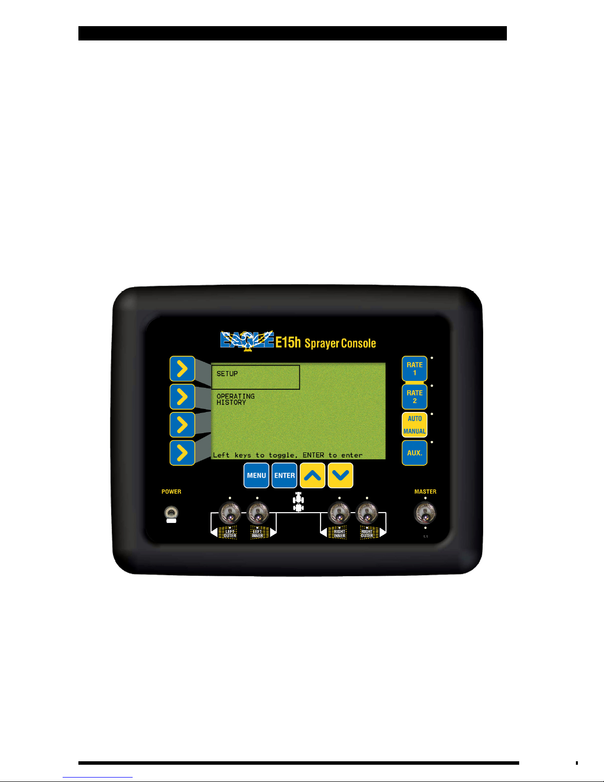
3.1 SET THE PRESET RATE 1
Note: This sets the “Main Target” Rate for the sprayer, and activated by the
RATE 1 button on the console.
• Press MENU
• Press ENTER to select SETUP
• Press ENTER to select SPRAYER SETUP.
The focus window will be on
TARGET RATE
• Press ‘RATE 1’ button.
The LED next to the ‘RATE 1’ button will light up.
The current TARGET RATE will be displayed in the window.
• Press ENTER to edit TARGET RATE.
An asterisk (*) should appear after
“TARGET RATE”
• Use Inc/Dec (Up and down arrows) to set the TARGET RATE 1
• Press ENTER to accept the changes
3.2
SET THE PRESET RATE 2
Note: This sets the “2nd Target” Rate for the sprayer, and is activated by the
RATE 2 button on the console.
• Press MENU
• Press ENTER to select SETUP
• Press ENTER to select SPRAYER SETUP.
The focus window will be on
TARGET RATE
• Press RATE 2 button.
The LED next to the RATE 2 button will light up.
The current TARGET RATE will de displayed in the window.
• Press ENTER to edit TARGET RATE.
An asterisk( *) should appear after
“TARGET RATE”
• Use INC/DEC buttons to set the TARGET RATE
• Press ENTER to accept the changes
3.3.
MINIMUM FLOW HOLD VALUE
NOTE: This feature alarms the operator when the flow of liquid going through
the flowmeter drops below the value set in the MINIMUM FLOW VALUE.To
switch the MINIMUM FLOW HOLD alarm ON or OFF, go to Section 4.1.1
If this feature is not required, then set the MINIMUM FLOW to ‘0’
• Press MENU
• Press ENTER to select SETUP
• Press ENTER to select SPRAYER SETUP
• Press LINE 1 button to move the focus to MINIMUM FLOW (1)
The current value
is displayed in the window.
• Press ENTER.
An asterisk (*) will be displayed after MINIMUM
• Press INC/DEC buttons, to set the MINIMUM FLOW value.
20
V 1.0 11/05
Page 21

E15h SPRAYER- Sprayer Setup Operation
3.4 SET THE PRESET ROW WIDTH and SECTION WIDTHS
Note: This sets the Section widths of each row. 4 Preset Widths can be set.
• Press MENU
• Press ENTER to select SETUP
• Press ENTER to select SPRAYER SETUP
• Press LINE 2 when the focus is on PRESET WIDTH.
This window shows
the current width of the sprayer. The number in the bracket displays which
Preset Width (1,2,3 or 4) the Total Width is representing.
• Press ENTER to advance to the next screen (Section Widths Setup), as
shown below.
TOTAL WIDTH
- window displays the current Preset Width selected, the
number in the bracket indicates which Preset Width is displayed.
4 Preset Widths can be stored,(1,2,3 or 4). The TOTAL WIDTH window
selects which Preset Width is to be edited.
ROW WIDTH-
Displays the current Row Width.
SECTIONS-
Displays the number of sections and section configurations,
these are set in Section 3.13. The section widths for each section are
displayed under each section. The Sections widths can be edited, as the
Sections are edited the TOTAL WIDTH and ROW WIDTHS will reflect the
changes made.
LEFT 2 represents LEFT OUTER on the console section switch.
LEFT 1 represents LEFT INNER on the console section switch.
RIGHT 1 represents RIGHT INNER on the console section switch.
RIGHT 2 represents RIGHT OUTER on the console section switch.
Section Widths Setup Screen
21
V 1.0 11/05
Page 22

E15h SPRAYER- Sprayer Setup Operation
• With the focus on TOTAL WIDTH. Press the INC or DEC buttons, to select the
Preset Width to change, (1,2,3 or 4). The current TOTAL WIDTH and ROW
WIDTH will be displayed for that number.
• Press the LINE 3 button, the focus will be on the first Section to be set.
• Press ENTER to edit the section width.
An asterisk (*) will appear.
• Use the INC/DEC buttons to change the section width.
As the section is changed
the TOTAL WIDTH and ROW WIDTH values will automatically change.
• Press ENTER to accept the changes
• Press the LINE 3 button to move the focus window to the next section that
requires setting.
• Use the INC/DEC buttons to change the section width.
As the section is changed
the TOTAL WIDTH and ROW WIDTH values will change accordingly
•
Repeat the process for as many section widths that need changing.
• Once all section widths have been entered for that Preset With, then select
another Preset Width Number.
• Press MENU to go back to the previous Spray Setup Screen.
V 1.0 11/05
22
Page 23

E15h SPRAYER- Sprayer Setup Operation
3.5 SET THE LOW SPEED SHUTOFF
Note: This sets the LOW SPEED SHUTOFF value, so when the boomspray slows
down below this value , the boom spray will turn all sections OFF, and the
sections will stay on HOLD, the regulator valve will hold the same position when
the ‘Low Speed Shutoff’ came into affect; till the boomspray increases speed
above the LOW SPEED SHUTOFF value.
• Press MENU
• Press ENTER to select SETUP
• Press ENTER to select SPRAYER SETUP
• Press LINE 2 button until the focus is on LOW SPEED SHUTOFF
• Press ENTER.
An asterisk (*) will appear after SPEED
• Use the INC/DEC buttons to change the LOW SPEED SHUTOFF value
• Press ENTER to accept the changes
3.6
SET THE TANK VOLUME
Note: This sets the size of the boomspray tank.
• Press MENU
• Press ENTER to select SETUP
• Press ENTER to select SPRAYER SETUP
• Press LINE 3 so the focus is on TANK VOLUME (1)
• Press ENTER.
An asterisk (*) will appear after
TANK
• Use the INC/DEC buttons to change the tank volume.
Volume
changes in 50 litres increments.
• Press ENTER to accept the changes
3.7
APPL’N MODE (Application Mode)
Note: This sets the way application rate is displayed on the ‘Working Screen, the
Rate can be displayed as volume/area OR volume/distance; eg.‘L/Ha’ or ‘L/100m.
• Press MENU
• Press ENTER to select SETUP
• Press ENTER to select SPRAYER SETUP
• Press LINE 3 until the focus is on APPL’N MODE
• Press ENTER.
An asterisk (*) will appear after
APPL’N.
• Use the INC/DEC buttons to select either ‘L/Ha’ or ‘L/100m’
• Press ENTER
to accept the changes.
23
V 1.0 11/05
Page 24

E15h SPRAYER- Sprayer Setup Operation
• Press MENU
• Press ENTER to select SETUP
• Press ENTER to select SPRAYER SETUP
• Press LINE 4 until the focus window is on SPEED CAL.
The focus window
displays the current SPEED CAL factor
• Press ENTER.
Screen will change to SPEED CAL SETUP screen. Go to Section 3.8.2
for Automatic Speed Calibration; or Section 3.8.3 for Manual Speed Calibration
Entry
When the STANDARD is selected for the SPEED SOURCE:
STANDARD is the default, which means the speed source is taken from the wheel
sensor on the Sprayer Loom.
This wheel factor value is the distance travelled by the sprayer, per pulse from
the wheel (speed)sensor. The value will vary considerably between different
sprayers, with typical values between .25 and 1 meter per pulse. Values more
than 5.0 meters will not give good spray rate control and must be avoided.
When the RADAR is selected for the SPEED SOURCE:
If the RADAR is selected, then the speed source is taken from the 3 pin weather
pak connector on the loom going into the back of the E15 console;
The RADAR SOURCE is used if the operator wants to use the tractor radar.
The wheel factor value will vary between different tractor radar models, a typical
value will be between 0.1 and 0.0005.
Speed Cal Screen
3.8 SET THE WHEEL CALIBRATION FACTOR
24
V 1.0 11/05
Page 25

E15h SPRAYER- Sprayer Setup Operation
3.8.1 SELECT SPEED SOURCE
• Press Line 4 to highlight SPEED SOURCE
• Press ENTER.
An asterisk (*) will appear.
• Use INC/DEC buttons to select STANDARD or RADAR.
• Press ENTER to accept changes.
3.8.2
AUTOMATIC WHEEL CALIBRATION
• Select Line 1 to highlight PULSES.
• Press ENTER to begin wheel factor calibration
• Drive forward a measured distance, say 100m.
The PULSES count will
accumulate as you travel forwards. The DISTANCE value and ESTIMATED value
will accumulate in metres as you travel forwards. These values will accumulate
reflecting the current WHEEL FACTOR value; if the value is close then then the
ESTIMATED and DISTANCE value will also be close to the actual distance
travelled.
The DISTANCE value is the value to be edited and the ESTIMATED value is
a display value only.
• Once the known distance is reached, press ENTER.
Focus will
automatically jump to
DISTANCE
line of the screen
• Use Inc/Dec buttons to change the DISTANCE value to reflect the actual
distance travelled
• Press ENTER to accept the value. The
Wheel factor will be automatically
calculated and displayed, on the SPEED CAL line.
3.8.3 MANUAL ENTRY OFF WHEEL FACTOR
• Press LINE 3 until the focus is on SPEED CAL
• Press ENTER to edit the value. An asterisk (*) will appear next to SPEED.
• Use INC/DEC buttons to change the wheel factor.
Wheel factor
changes in 1cm increments, when STANDARD is selected. The Increment
changes are a lot smaller when RADAR is selected.
• Press ENTER to accept the value
• Press MENU to go back to previous Sprayer Setup Screen
25
V 1.0 11/05
Page 26
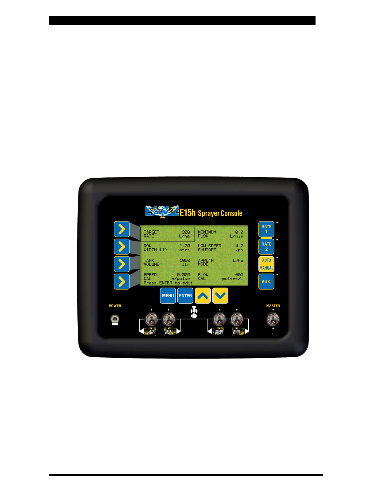
3.9 SET THE FLOW CALIBRATION FACTOR
E15h SPRAYER- Sprayer Setup Operation
• Press MENU
• Press ENTER to select SETUP
• Press ENTER to select SPRAYER SETUP
• Press LINE 4 twice until the focus is on FLOW CAL.
The focus window will
display the current FLOW CAL factor in pulses/volume
• Press ENTER.
Screen will advance to FLOW CAL SETUP screen. Go to Section
3.9.1 to continue setup using Automatic Flow Calibration method
or
go to
Section 3.9.2 to manually enter the Flow Calibration which is located on the
Flow Meter body, on the sprayer. The number located on the Flow Meter must
be in “pulses per volume” for the number to be entered in manually. The
number used must reflect the units selected in the console. For example if the
number is in ‘pulses per litre’ then ‘Metric’ must be selected in console units.
See Section 3.25 to select ‘Console Units’.
Flow Cal Screen
26
V 1.0 11/05
Page 27

E15h SPRAYER- Sprayer Setup Operation
3.9.1 AUTOMATIC FLOW CALIBRATION
• Fully prime the flow sensor and hose
• Disconnect one of the section lines from the spray manifold
• Place a bucket under the output of the section valve
• Ensure the relevant boom section switch is switched ON, on the console.
• Press ENTER to begin flow factor calculation
• The valve will open and fluid will begin to pump through the manifold.
The
pulse count will begin accumulating as you meter out liquid
• Once a sufficient volume has accumulated( 20 litres is a good amount), press
ENTER, this will automatically turn OFF the section valve. The
Focus will
automatically jump to ACTUAL FLOW line of the screen
• Use INC/DEC buttons to change the volume, to reflect the actual
volume collected in the bucket
• Press ENTER to accept the value.
Flow cal factor will be automatically
calculated and displayed.
3.9.2 MANUAL FLOW CALIBRATION
Note: If the Flow Meter has a ‘Flow Cal’ value stamped on the flow meter then
that value can be entered in here. The value must be in “pulses per volume”. The
units that are stamped on the‘Flow Cal’, must be the same units, the E15 console
is using; otherwise a conversion will have to be performed.
• Press LINE 3 until the focus is on FLOW CAL
• Press ENTER to edit the value
• Press INC/DEC buttons to change the FLOW CAL factor
• Press ENTER to accept the value
Note: Press MENU to get back to the previous Sprayer Setup Screen once the
calibration is finished.
27
V 1.0 11/05
Page 28

E15h SPRAYER- Sprayer Setup Operation
3.10 SPRAYER SETUP 2 MENU
Sprayer Setup 2 Screen
• Press MENU
• Press ENTER to select SETUP
• Press ENTER to select SPRAYER SETUP
• Press the DEC button to advance to the SPRAYER SETUP 2 screen
28
V 1.0 11/05
Page 29

E15h SPRAYER- Sprayer Setup Operation
3.11 SET A MANUAL SPEED
• Press MENU
• Press ENTER to select SETUP
• Press ENTER to select SPRAYER SETUP
• Press Dec (down arrow), the screen advances to SPRAYER SETUP 2
• Press LINE 1 until focus is on MANUAL SPEED
• Press ENTER,
An asterisk (*) will appear after MANUAL
• Press INC/DEC buttons to set the manual speed.
A value of OFF and
number between 1 kph and 40kph can be set.
• Press ENTER, to accept changes
Note: The manual speed will not be able to be set if there is a valid speed
source present, this can only be done whilst the vehicle is stationary. As soon as
a valid speed is present this will override the manual speed. This value is not
saved in memory, if the console is turned OFF the ‘Manual Speed’ value will
need to be re-entered
3.12 SET RATE INCREMENT
Note: The units displayed will be (L/Ha or L/100m), for the rate increment, this
will depend on whether ‘L/Ha’ or ‘L/100m’ was selected for the APPL’N MODE.
See Section 3.7.
• Press MENU
• Press ENTER to select SETUP
• Press ENTER to select SPRAYER SETUP
• Press Dec (down arrow), the screen advances to SPRAYER SETUP 2
• Press LINE 1 until the focus is on RATE INCREMENT
• Press ENTER.
An asterisk (*) will appear after RATE
• Press INC/DEC buttons, to set RATE INCREMENT value.
Rate increment values changes in 1 (L/ha or L/100m) increments.
• Press ENTER to accept the changes
3.13
SET THE NUMBER OF BOOM SECTIONS
Note: This sets the number boom sections and the configuration of boom
sections to suit the sprayer configuration being used.
When 2 sections are selected then ‘Left Inner’ and ‘Right Inner’ section switches
are enabled.
When ‘3L’ sections are selected then ‘Left Outer’, ‘Left Inner’ and ‘Right Inner’
section switches are enabled.
When ‘3R’ sections are selected then ‘Left Inner’, Right Inner’ and ‘Right Outer’
section switches are enabled.
When ‘4’ is selected then the ‘Left Outer’, ‘Left Inner’, ‘Right Inner’ and ‘Right
Outer’ section switches are selected
• Press MENU
• Press ENTER to select SETUP
• Press ENTER to select SPRAYER SETUP
• Press Dec (down arrow), the screen advances to SPRAYER SETUP 2
• Press LINE 2, until the focus is on BOOM SECTIONS.
The focus window displays
the number of sections and sprayer configuration currently selected.
• Press ENTER to set the number and configuration of BOOM SECTIONS.
An asterisk (*) will appear.
• Press INC/DEC buttons, to select between ‘2’, ‘3L’, ‘3R’ and 4 SECTIONS
• Press ENTER to accept the changes
29
V 1.0 11/05
Page 30

E15h SPRAYER- Sprayer Setup Operation
3.14 ENABLE DATA LOGGER
Note: Only enable the ‘Data Logger’ if an optional A1920 Data Logger kit is
connected to the CON 3 plug at the back of the E15h console.
• Press MENU
• Press ENTER to select SETUP
• Press ENTER to select SPRAYER SETUP
• Press Dec (down arrow), the screen advances to SPRAYER SETUP 2
• Press LINE 2 until focus is on DATA LOGGER
• Press ENTER.
An asterisk (*) will appear.
• Press INC/DEC buttons, to select ON or OFF.
• Press ENTER to accept changes.
3.15
ENABLE FLUSH OUTPUT
Note: This feature can only be enabled when the ‘Fully Featured Horticultural
Loom’ is fitted to the sprayer.
• Press MENU
• Press ENTER to select SETUP
• Press ENTER to select SPRAYER SETUP
• Press Dec (down arrow), the screen changes to SPRAYER SETUP 2
• Press LINE 3. The focus will be on FLUSH ENABLED
• Press ENTER.
An asterisk (*) will appear.
• Press INC/DEC buttons, to select both FLUSH ON or OFF
OUTPUTS, ON or OFF.
When the FLUSH AND AUXILIARY OUTPUTS are switched
ON, this enables two relays within the console. The FLUSH function enables the
operator to flush the spray boom out with clean water. Connect the solenoid on
the Flush Line to the plug marked “Flush” on the F/F “Horticultural Sprayer
Loom”.When the FLUSH function is enabled ON, then a FLUSH TIME is enabled,
on LINE 4 in the right column and a FLUSH TIME value is able to be entered.
• Press ENTER to accept changes
3.16 SET FLUSH TIME
• Press MENU
• Press ENTER to select SETUP
• Press ENTER to select SPRAYER SETUP
• Press Dec (down arrow), the screen advances to the SPRAYER SETUP 2 screen
• Press LINE 4. The focus will be on FLUSH AND AUXILIARY
• Press ENTER.
An asterisk (*) will appear.
• Press INC/DEC buttons, enable FLUSH ENABLED, ON.
It must be switched ON to
allow a FLUSH TIME value to be entered
• Press LINE 4, to highlight FLUSH TIME
• Press ENTER to edit the value.
An asterisk (*) will appear.
• Press INC/DEC buttons, to set the FLUSH TIME, values can be set
between 10 and 60 seconds, increments are in 5 second steps.
• Press ENTER to accept changes
30
V 1.0 11/05
Page 31

E15h SPRAYER- Sprayer Setup Operation
3.17 ENABLE FULL ROW PER SECTION
Note: By default this function is selected OFF; therefore each section switch,
switches half a row ON and OFF.
When FULL ROW PER SECTION is enabled ON, then each section switch, switches
1 row ON and OFF. For example a 2 row sprayer which has only 1 solenoid
controlling each row, then ‘2’ sections would be selected in BOOM SECTIONS,
(see Section 3.13) and FULL ROW PER SECTION enabled ON.
• Press MENU
• Press ENTER to select SETUP
• Press ENTER to select SPRAYER SETUP
• Press DEC (down arrow) button, the screen advances to SPRAYER SETUP 2
• Press LINE 4 until focus is on FULL ROW PER SECTION
• Press ENTER.
An asterisk (*) will appear.
• Press INC/DEC buttons, to select ON or OFF.
• Press ENTER to accept changes.
3.18
ENABLE AUXILIARY FUNCTION
Note: The AUXILIARY function enables the operator to connect a set of lights OR
foam marker to the AUXILIARY plug on the sprayer wiring loom and switch the
lights OR foam marker ON or OFF from the console.
• Press MENU
• Press ENTER to select SETUP
• Press ENTER to select SPRAYER SETUP
• Press DEC (down arrow) button, the screen advances to SPRAYER SETUP 2
• Press LINE 4 until focus is on FULL ROW PER SECTION
• Press ENTER.
An asterisk (*) will appear.
• Press INC/DEC buttons, to select ON or OFF.
• Press ENTER to accept changes.
31
V 1.0 11/05
Page 32

E15h SPRAYER- Sprayer Setup Operation
3.19 SPRAYER SETUP 3 MENU
Sprayer Setup 3 Screen
• Press MENU
• Press ENTER to select SETUP
• Press ENTER to select SPRAYER SETUP
• Press the DEC button to advance to the SPRAYER SETUP 2 screen
• Press the DEC button to advance to the SPRAYER SETUP 3 screen
V 1.0 11/05
32
Page 33

E15h SPRAYER- Sprayer Setup Operation
3.20 ENABLE PUMP SPEED SENSOR
Note: Select ON if a PUMP SPEED SENSOR is fitted to the sprayer loom, to the
plug marked PUMP SPEED. The PUMP SPEED plug is only available on the ‘FULLY
FEATURED HORTICULTURAL LOOM’.
When enabled ON , the PUMP SPEED RPM can be displayed in the FLOW RATE
window.
• Press MENU
• Press ENTER to select SETUP
• Press ENTER to select SPRAYER SETUP
• Press the DEC button to advance to the SPRAYER SETUP 2 screen
• Press the DEC button to advance to the SPRAYER SETUP 3 screen
• Press LINE 1, to highlight PUMP SPEED SENSOR
• Press ENTER to edit the PUMP SPEED SENSOR.
• Press INC/DEC buttons, to enable the PUMP SPEED SENSOR ON or OFF
• Press ENTER to accept changes
3.21
ENABLE AUXILIARY SHAFT SENSOR
Note: Select ON if a AUXILIARY SHAFT SENSOR is fitted to the sprayer loom, to
the plug marked AUXILIARY SHAFT The AUXILIARY SHAFT plug is only available
on the ‘FULLY FEATURED HORTICULTURAL LOOM’.
When enabled ON , the AUXILIARY SHAFT RPM can be displayed in the FLOW
RATE window.
• Press MENU
• Press ENTER to select SETUP
• Press ENTER to select SPRAYER SETUP
• Press the DEC button to advance to the SPRAYER SETUP 2 screen
• Press the DEC button to advance to the SPRAYER SETUP 3 screen
• Press LINE 1, to highlight AUX. SHAFT SENSOR
• Press ENTER to edit the AUX.SHAFT SENSOR.
• Press INC/DEC buttons, to enable the AUX. SHAFT SENSOR ON or OFF
• Press ENTER to accept changes
3.22
ENABLE DUMP OVERRIDE
Note: Select ON to enable the DUMP OVERRIDE feature. This allows a Chemical
Induction Pump to suck premix chemical into the main tank. Don’t enable this
function unless your sprayer has been plumbed up correctly. When enabled ON ,
the DUMP OVERRIDE can be displayed in the VOLUME USED window.
• Press MENU
• Press ENTER to select SETUP
• Press ENTER to select SPRAYER SETUP
• Press the DEC button to advance to the SPRAYER SETUP 2 screen
• Press the DEC button to advance to the SPRAYER SETUP 3 screen
• Press LINE 2, to highlight DUMP OV’RIDE ENABLED
• Press ENTER to edit the DUMP OV’RIDE ENABLED.
• Press INC/DEC buttons, to enable the DUMP OV’RIDE ENABLED ON or OFF
• Press ENTER to accept changes
33
V 1.0 11/05
Page 34

E15h SPRAYER- Sprayer Setup Operation
3.23 SELECT DUMP MODE
Note: If connecting a DUMP VALVE to the ‘37 Pin’ plug marked DUMP on the
sprayer loom, then select STANDARD. STANDARD is the default. Normally
STANDARD is selected when using a ‘Fully Featured Horticultural Loom’.
If connecting the DUMP valve to the ‘24 Pin’ plug marked ‘SECT. 6’ on the
‘Economy Sprayer’ or using the ‘Horticultural Adaptor’ loom, then select ‘SECT 6’.
• Press MENU
• Press ENTER to select SETUP
• Press ENTER to select SPRAYER SETUP
• Press the DEC button to advance to the SPRAYER SETUP 2 screen
• Press the DEC button to advance to the SPRAYER SETUP 3 screen
• Press LINE 1, to highlight DUMP MODE
• Press ENTER to edit the DUMP MODE.
• Press INC/DEC buttons, to select the DUMP MODE as STANDARD OR SECT. 6.
• Press ENTER to accept changes
3.24
SET THE VALVE TYPE
*Note: If connecting the sprayer loom to ‘2 Wire Valves’ via an ARAG interface
then select SOLENOID as the VALVE TYPE.
Only select ‘2 Wire Valves’ as the VALVE TYPE when the sprayer loom connects
directly to the ‘2 Wire Valves’.
• Press MENU
• Press ENTER to select SETUP
• Press ENTER to select SPRAYER SETUP
• Press the DEC button to advance to the SPRAYER SETUP 2 screen
• Press the DEC button to advance to the SPRAYER SETUP 3 screen
• Press LINE 3, to highlight VALVE TYPE
• Press ENTER to edit VALVE TYPE.
An asterisk (*) will appear.
• Press INC/DEC buttons, to select between SOLENOID, 2-WIRE*
or 3-WIRE.
• Press ENTER to accept the changes
3.25
SET THE CONSOLE UNITS
Note: Default is METRIC.
• Press MENU
• Press ENTER to select SETUP
• Press ENTER to select SPRAYER SETUP
• Press the DEC button to advance to the SPRAYER SETUP 2 screen
• Press the DEC button to advance to the SPRAYER SETUP 3 screen
• Press LINE 3, to highlight CONSOLE UNITS
• Press ENTER to edit CONSOLE UNITS.
An asterisk (*) will appear.
• Press INC/DEC buttons, to select between: METRIC, IMP’L(IMPERIAL),
U.S.(U.S. IMPERIAL), CAN. IMP(CANADIAN IMPERIAL),
or CAN.MET(CANADIAN METRIC)
• Press ENTER to accept the changes
V 1.0 11/05
34
Page 35

E15h SPRAYER- Sprayer Setup Operation
Note: If no fans are to be monitored then set FAN MONITOR to OFF and set
FANS ENABLED to ‘0’
When FAN MONITOR is selected to OFF, then there is noFAN MONITOR ECU
fitted to the E15 h console. When FAN MONITOR is selected to ON, then there is
a FAN MONITOR ECU connected to the E15h console
If a ‘Fully Featured Horticultural Loom’ is fitted to the sprayer then up to 2 fan
imputs can be monitored, without the need to install a FAN MONITOR ECU. In
this case select FAN MONITOR to OFF and select either 1 or 2 from FANS
ENABLED.
If the Economy Horticultural Loom is fitted OR more than 2 fans need to be
monitored then a Fan Monitor ECU needs to be installed. In this case select FAN
MONITOR to ON and then select the number of fans to be monitored from FANS
ENABLED.
The Fan Monitor ECU can monitor up to 12 fans.
3.26 ENABLE FAN MONITORING
• Press MENU
• Press ENTER to select SETUP
• Press ENTER to select SPRAYER SETUP
• Press the DEC button to advance to the SPRAYER SETUP 2 screen
• Press the DEC button to advance to the SPRAYER SETUP 3 screen
• Press LINE 4, to highlight FAN MONITOR
• Press ENTER to edit the FAN MONITOR.
• Press INC/DEC buttons, to select either ON (if a FAN MONITOR ECU is
connected) OR OFF ( if noFAN MONITOR ECU is connected).
• Press ENTER to accept changes.
3.27
SET NUMBER OF FANS
• Press MENU
• Press ENTER to select SETUP
• Press ENTER to select SPRAYER SETUP
• Press the DEC button to advance to the SPRAYER SETUP 2 screen
• Press the DEC button to advance to the SPRAYER SETUP 3 screen
• Press LINE 4, to highlight FANS ENABLED
• Press ENTER to edit the FANS ENABLED.
• Press INC/DEC buttons, to set the number of fans to be monitored.
Note: If FAN MONITOR was selected to OFF, then only ‘0’ (monitoring no fans),
‘1’ (monitoring 1 fan) OR ‘2’ (monitoring 2 fans) can be selected.
If FAN MONITOR was selected to ON, then select between ‘2’, ‘4’, ‘6’, ‘8’, ‘10’, or
‘12’ fans to monitor.
• Press ENTER to accept changes.
V 1.0 11/05
35
Page 36

3.28 SPRAYER SETUP 4 MENU
Sprayer Setup 4 Screen
• Press MENU
• Press ENTER to select SETUP
• Press ENTER to select SPRAYER SETUP
• Press the DEC button to advance to the SPRAYER SETUP 2 screen
• Press the DEC button to advance to the SPRAYER SETUP 3 screen
• Press the DEC button to advance to the SPRAYER SETUP 4 screen
E15h SPRAYER- Sprayer Setup Operation
V 1.0 11/05
36
Page 37

E15h SPRAYER- Sprayer Setup Operation
3.29 ENABLE PRESSURE1 SENSOR
Note: Select ON if a pressure transducer is fitted to the plug marked “PRESSURE
SENSOR” on the Sprayer Loom.
• Press MENU
• Press ENTER to select SETUP
• Press ENTER to select SPRAYER SETUP
• Press the DEC button to advance to the SPRAYER SETUP 2 screen
• Press the DEC button to advance to the SPRAYER SETUP 3 screen
• Press the DEC button to advance to the SPRAYER SETUP 4 screen
• Press LINE 1, to highlight PRESSURE1 SENSOR
• Press ENTER to edit the PRESSURE1 SENSOR.
• Press INC/DEC buttons, to enable the PRESSURE1 SENSOR ON or OFF
• Press ENTER to accept changes
3.30
SETTING THE PRESSURE GAIN
Note: PRESSURE GAIN is setting the gain for the pressure sensor connected to the
plug marked “PRESSURE SENSOR” on the “Sprayer Loom”. The default is “x2”
Only use “x1” if the Eagle E15h console was purchased before June 2005.
• Press MENU
• Press ENTER to select SETUP
• Press ENTER to select SPRAYER SETUP
• Press the DEC button to advance to the SPRAYER SETUP 2 screen
• Press the DEC button to advance to the SPRAYER SETUP 3 screen
• Press the DEC button to advance to the SPRAYER SETUP 4 screen
• Press LINE 3, to highlight PRESSURE GAIN (1)
• Press ENTER to edit the PRESSURE GAIN (1)
• Press INC/DEC buttons, select between 1x or 2x
• Press ENTER to accept changes
3.31
SETTING THE TYPE OF PRESSURE SENSOR
Note: PRESSURE SENSOR is sets the type of pressure sensor connected to the plug
marked “PRESSURE SENSOR” on the “Sprayer Loom”
The default is 5 BAR. Most sprayers will use this setting.
10 BAR Pressure Sensors is only used for special purposes like “Air Blast” sprayers
• Press MENU
• Press ENTER to select SETUP
• Press ENTER to select SPRAYER SETUP
• Press the DEC button to advance to the SPRAYER SETUP 2 screen
• Press the DEC button to advance to the SPRAYER SETUP 3 screen
• Press the DEC button to advance to the SPRAYER SETUP 4 screen
• Press LINE 4, to highlight PRESSURE SENSOR
• Press ENTER to edit the PRESSURE SENSOR
• Press INC/DEC buttons, select between 5BAR or 10BAR
• Press ENTER to accept changes
V 1.0 11/05
37
Page 38

E15h SPRAYER- Sprayer Setup Operation
3.32 PRESSURE SENSOR 1 CALIBRATION
Pressure Cal Screen
38
V 1.0 11/05
Page 39

E15h SPRAYER- Sprayer Setup Operation
3.32 PRESSURE SENSOR 1 CALIBRATION
Note: A “Glass Pressure Gauge” should be connected as close to the electronic
pressure sensor as possible. The “Glass Gauge” will give the actual pressure, so
the electronic pressure transducer can be calibrated.
• Press MENU
• Press ENTER to select SETUP
• Press ENTER to select SPRAYER SETUP
• Press the DEC button to advance to the SPRAYER SETUP 2 screen
• Press the DEC button to advance to the SPRAYER SETUP 3 screen
• Press the DEC button to advance to the SPRAYER SETUP 4 screen
• Press LINE 2 to highlight PRESSURE CAL
• Press ENTER,
screen will change to Pressure Calibration Screen. ‘TURN PUMP
OFF’. is highlighted
• Turn pump OFF
. Make sure the spray pump is turned OFF
• Press ENTER.
The focus window will move to the next window ‘IS PUMP OFF?’
then Press ENTER. at this point the Eagle console is taking a zero point for the
electronic pressure sensor while the spray pump is switched OFF.
• Switch the pump ON; switch the sections ON; switch the MASTER ON; and take
the pump up to ‘operating pressure’; once at operating pressure.
• Press ENTER the focus window will move to ‘IS PUMP AT OPERATING
PRESSURE’, reminding the operator to have the spray pump at operating
pressure.
• Press ENTER again to move the focus window to ACTUAL PRESSURE.
• Press ENTER to edit the ACTUAL PRESSURE.
An asterisk (*) will appear.
• Press the INC/DEC buttons, till the actual pressure as displayed by the
“Glass Pressure Gauge” is reflected in ACTUAL PRESSURE” window.
• Press ENTER to accept changes
V 1.0 11/05
39
Page 40

4.0 ALARMS SETUP MENU
Alarms Menu Setup
40
E15h SPRAYER- Alarm Setup
V 1.0 11/05
• Press MENU
• Press ENTER to select SETUP
• Press LINE 2, the focus is on ALARM SETUP
• Press ENTER to select ALARM SETUP
Page 41

E15h SPRAYER- Alarm Setup
4.1 RATE ALARMS
Rate Alarms Screen
V 1.0 11/05
41
• Press MENU
• Press ENTER to select SETUP
• Press LINE 2, the focus is on ALARM SETUP
• Press ENTER to select ALARM SETUP
• Press ENTER to select RATE ALARMS
Page 42

E15h SPRAYER- Alarm Setup
4.1 RATE ALARMS
4.1.1 ENABLE THE MINIMUM FLOW ALARM
NOTE: To set the MINIMUM FLOW value, see Section 3.3.
• Press MENU
• Press ENTER to select SETUP
• Press LINE 2, the focus is on ALARM SETUP
• Press ENTER to select ALARM SETUP
• Press ENTER to select RATE ALARMS
• Press ENTER to select MIN FLOW ALARM.
An asterisk (*) will be displayed
• Press INC/DEC buttons, to set the alarm ON or OFF
• Press ENTER to accept the changes
4.1.2
ENABLE THE APPLICATION RATE LOW ALARM
• Press MENU
• Press ENTER to select SETUP
• Press LINE 2, the focus is on ALARM SETUP
• Press ENTER to select ALARM SETUP
• Press ENTER to select RATE ALARMS
• Press LINE 2, the focus is on RATE LOW ALARM
• Press ENTER to select RATE LOW ALARM.
An asterisk( *) will be displayed
• Press INC/DEC buttons, to set the alarm ON or OFF
• Press ENTER to accept the changes
4.1.3 SET THE APPLICATION RATE LOW ALARM POINT
• Press MENU
• Press ENTER to select SETUP
• Press LINE 2, the focus is on ALARM SETUP
• Press ENTER to select ALARM SETUP
• Press ENTER to select RATE ALARMS
If alarm is OFF, switch the alarm ON as previously explained in Section 4.1.2
• Press LINE 2 twice to move the focus to ALARM POINT
• Press ENTER to edit the value.
An asterisk(*) will be displayed
• Press INC/DEC buttons, to set the ALARM POINT as a percentage (%).
• Press ENTER to accept the changes.
42
V 1.0 11/05
Page 43

E15h SPRAYER- Alarm Setup
4.1.4
ENABLE THE APPLICATION RATE HIGH ALARM
• Press MENU
• Press ENTER to select SETUP
• Press LINE 2, the focus is on ALARM SETUP
• Press ENTER to select ALARM SETUP
• Press ENTER to select RATE ALARMS
• Press LINE 3, the focus is on RATE LOW ALARM
• Press ENTER to select RATE HIGH.
An asterisk (*) will be displayed
• Press INC/DEC buttons, to set the alarm ON or OFF
• Press ENTER to accept the changes
4.1.5
SET THE APPLICATION RATE HIGH ALARM POINT
• Press MENU
• Press ENTER to select SETUP
• Press LINE 2, the focus is on ALARM SETUP
• Press ENTER to select ALARM SETUP
• Press ENTER to select RATE ALARMS
Note:If alarm is OFF, switch the alarm ON as previously explained in Section 4.1.4
• Press LINE 3 twice to move the focus to ALARM POINT
• Press ENTER to edit the value.
An asterisk (*) will be displayed
• Press INC/DEC buttons to set the ALARM POINT as a percentage (%).
• Press ENTER to accept the changes
43
V 1.0 11/05
Page 44

E15h SPRAYER- Alarm Setup
4.2 SHAFT ALARMS
Shaft Alarms Screen
44
V 1.0 11/05
Page 45

E15h SPRAYER- Alarm Setup
NOTE: For the PUMP LOW SPEED and PUMP HIGH SPEED ALARMS to be enabled
on the SHAFT ALARMS screen, the PUMP SPEED SENSOR has to be set to ON.
See Section 3.22 to enable the PUMP SPEED SENSOR ON or OFF
4.2.1 ENABLE THE PUMP SPEED LOW ALARM
• Press MENU
• Press ENTER to select SETUP
• Press LINE 2 the focus is on ALARM SETUP
• Press ENTER to select ALARM SETUP
• Press LINE 2, the focus is on SHAFT ALARMS
• Press ENTER to select SHAFT ALARMS
• Press ENTER to edit PUMP SPEED LOW.
An asterisk(*) will be displayed
• Press INC/DEC buttons, to set the alarm ON or OFF
• Press ENTER to accept the changes
4.2.2
SET THE PUMP SPEED LOW ALARM POINT
• Press MENU
• Press ENTER to select SETUP
• Press LINE 2 the focus is on ALARM SETUP
• Press ENTER to select ALARM SETUP
• Press LINE 2, the focus is on SHAFT ALARMS
• Press ENTER to select SHAFT ALARMS
Note:
If alarm is OFF, to switch the alarm ON, see Section 4.2.1
•Press LINE 1 until the focus is on the ALARM POINT
• Press ENTER to edit the value.
An asterisk(*) will be displayed
• Use INC/DEC buttons, to set the alarm point in 50 rpm increments
• Press ENTER to accept the changes
4.2.3
ENABLE THE PUMP SPEED HIGH ALARM
• Press MENU
• Press ENTER to select SETUP
• Press LINE 2 the focus is on ALARM SETUP
• Press ENTER to select ALARM SETUP
• Press LINE 2, the focus is on SHAFT ALARMS
• Press ENTER to select SHAFT ALARMS
• Press LINE 2, the focus is on PUMP SPEED HIGH
• Press ENTER to edit PUMP SPEED HIGH.
An asterisk (*) will be displayed
• Press INC/DEC buttons, to switch the alarm ON or OFF
• Press ENTER to accept the changes
45
V 1.0 11/05
Page 46

E15h SPRAYER- Alarm Setup
4.2.4 SET THE PUMP SPEED HIGH ALARM POINT
• Press MENU
• Press ENTER to select SETUP
• Press LINE 2 the focus is on ALARM SETUP
• Press ENTER to select ALARM SETUP
• Press LINE 2, the focus is on SHAFT ALARMS
• Press ENTER to select SHAFT ALARMS
• If alarm is off, turn the alarm ON, see Section 4.2.3
• Press LINE 2 until the focus is on the ALARM POINT
• Press ENTER to edit the value.
An asterisk (*) will be displayed
• Press INC/DEC buttons, to set the alarm point in 50rpm increments
• Press ENTER to accept the changes
4.2.5
ENABLE THE AUX SHAFT LOW ALARM
NOTE: For the AUX SHAFT LOW and AUX SHAFT HIGH ALARMS to be enabled on
the SHAFT ALARMS screen, the AUX SHAFT SENSOR has to be toggled ON.
See Section 3.22 to switch the AUX SHAFT SENSOR ON or OFF
• Press MENU
• Press ENTER to select SETUP
• Press LINE 2 the focus is on ALARM SETUP
• Press ENTER to select ALARM SETUP
• Press LINE 2, the focus is on SHAFT ALARMS
• Press ENTER to select SHAFT ALARMS
• Press LINE 3, the focus is on AUX SHAFT LOW
• Press ENTER to edit AUX SHAFT LOW.
An asterisk (*) will be displayed
• Press INC/DEC buttons to switch the alarm ON or OFF
• Press ENTER to accept the changes
4.2.6
SET THE AUX SHAFT LOW ALARM POINT
• Press MENU
• Press ENTER to select SETUP
• Press LINE 2 the focus is on ALARM SETUP
• Press ENTER to select ALARM SETUP
• Press LINE 2, the focus is on SHAFT ALARMS
• Press ENTER to select SHAFT ALARMS
Note: If alarm is OFF, switch the alarm ON, see Section 4.2.5
• Press LINE 3 until the focus is on the ALARM POINT
• Press ENTER to edit the value.
An asterisk (*) will be displayed
• Press INC/DEC buttons, to set the alarm point in 50rpm increments
• Press ENTER to accept the changes
46
V 1.0 11/05
Page 47

E15h SPRAYER- Alarm Setup
4.2.7 ENABLE THE AUX SHAFT HIGH ALARM
• Press MENU
• Press ENTER to select SETUP
• Press LINE 2 the focus is on ALARM SETUP
• Press ENTER to select ALARM SETUP
• Press LINE 2, the focus is on SHAFT ALARMS
• Press ENTER to select SHAFT ALARMS
• Press LINE 4, the focus is on AUX SHAFT HIGH
• Press ENTER to edit AUX SHAFT HIGH.
An asterisk (*) will be displayed
• Press INC/DEC buttons, to enable the alarm ON or OFF
• Press ENTER to accept the changes
4.2.8
SET THE AUX SHAFT HIGH ALARM POINT
• Press MENU
• Press ENTER to select SETUP
• Press LINE 2 the focus is on ALARM SETUP
• Press ENTER to select ALARM SETUP
• Press LINE 2, the focus is on SHAFT ALARMS
• Press ENTER to select SHAFT ALARMS
Note: If alarm is OFF, to switch the alarm ON, see Section 4.2.7
• Press LINE 4 until the focus is on the ALARM POINT
• Press ENTER to edit the value.
An asterisk (*) will be displayed
• Press INC/DEC buttons, to set the alarm point in 50rpm increments
• Press ENTER to accept the changes
47
V 1.0 11/05
Page 48

E15h SPRAYER- Alarm Setup
4.3 SPEED ALARMS
• Press MENU
• Press ENTER to select SETUP
• Press LINE 2 the focus is on ALARM SETUP
• Press ENTER to select ALARM SETUP
• Press LINE 3, the focus is on SPEED ALARMS
• Press ENTER to select SPEED ALARMS
Speed Alarms Screen
48
V 1.0 11/05
Page 49

E15h SPRAYER- Alarm Setup
4.3.1 ENABLE THE SPEED LOW ALARM
• Press MENU
• Press ENTER to select SETUP
• Press LINE 2 the focus is on ALARM SETUP
• Press ENTER to select ALARM SETUP
• Press LINE 3, the focus is on SPEED ALARMS
• Press ENTER to select SPEED ALARMS
• Press ENTER to edit SPEED LOW.
An asterisk (*) will be displayed
• Press INC/DEC buttons, to set the alarm ON or OFF
• Press ENTER to accept the changes
4.3.2
SET THE SPEED LOW ALARM POINT
• Press MENU
• Press ENTER to select SETUP
• Press LINE 2, the focus is on ALARM SETUP
• Press ENTER to select ALARM SETUP
• Press LINE 3 the focus is on SPEED ALARMS
• Press ENTER to select SPEED ALARMS
• Press LINE 1, until focus is on ALARM POINT
Note: If alarm is OFF, switch the alarm ON. See Section 4.3.1
• Press ENTER to edit the value.
An asterisk (*) will be displayed
• Press INC/DEC buttons, to set the alarm point
• Press ENTER to accept the changes
4.3.3
ENABLE THE SPEED HIGH ALARM
• Press MENU
• Press ENTER to select SETUP
• Press LINE 2 the focus is on ALARM SETUP
• Press ENTER to select ALARM SETUP
• Press LINE 3, the focus is on SPEED ALARMS
• Press ENTER to select SPEED ALARMS
• Press LINE 2, the focus is on SPEED HIGH
• Press ENTER to edit SPEED HIGH.
An asterisk (*) will be displayed
• Press INC/DEC buttons, to set the alarm ON or OFF
• Press ENTER to accept the changes
49
V 1.0 11/05
Page 50

E15h SPRAYER- Alarm Setup
4.3.4
SET THE SPEED HIGH POINT
• Press MENU
• Press ENTER to select SETUP
• Press LINE 2, the focus is on ALARM SETUP
• Press ENTER to select ALARM SETUP
• Press LINE 3, the focus is on SPEED ALARMS
• Press ENTER to select SPEED ALARMS
Note: If alarm is off, turn the alarm on. See Section 4.3.3
• Press LINE 2, until focus is on ALARM POINT
• Press ENTER to edit the value.
An asterisk (*) will be displayed
• Press INC/DEC buttons, to set the alarm point
• Press ENTER to accept the changes
50
V 1.0 11/05
Page 51

E15h SPRAYER- Tank Alarm
4.4 TANK ALARMS
• Press MENU
• Press ENTER to select SETUP
• Press LINE 2, the focus is on ALARM SETUP
• Press ENTER to select ALARM SETUP
• Press LINE 4, the focus is on TANK ALARMS
• Press ENTER to select TANK ALARMS
Tank Alarms Screen
51
V 1.0 11/05
Page 52

4.4.1
ENABLE THE VOLUME LOW ALARM
• Press MENU
• Press ENTER to select SETUP
• Press LINE 2, the focus is on ALARM SETUP
• Press ENTER to select ALARM SETUP
• Press LINE 4, the focus is on TANK ALARMS
• Press ENTER to select TANK ALARMS
• Press ENTER to edit VOLUME LOW (1).
An asterisk (*) will be displayed
• Press INC/DEC buttons to set the alarm ON or OFF
• Press ENTER to accept the changes
4.4.2
SET THE VOLUME LOW POINT
• Press MENU
• Press ENTER to select SETUP
• Press LINE 2 the focus is on ALARM SETUP
• Press ENTER to select ALARM SETUP
• Press LINE 4, the focus is on TANK ALARMS
• Press ENTER to select TANK ALARMS
Note: If alarm is OFF, switch the alarm ON. See Section 4.4.1
• Press LINE 1, to move to the ALARM POINT
• Press ENTER to edit the value.
An asterisk (*) will be displayed
• Press INC/DEC buttons, to set the alarm point, in 10L increments.
• Press ENTER to accept the changes
E15h SPRAYER - Tank Alarms
52
V 1.0 11/05
Page 53

E15h SPRAYER- Pressure Alarm
4.5 PRESSURE ALARMS
• Press MENU
• Press ENTER to select SETUP
• Press LINE 2 the focus is on ALARM SETUP
• Press ENTER to select ALARM SETUP
• Press LINE 1,until the focus is on PRESSURE ALARMS
• Press ENTER to select PRESSURE ALARMS
Pressure Alarms Screen
53
V 1.0 11/05
Page 54

E15h SPRAYER- Pressure Alarm
4.5.1 ENABLE THE PRESSURE 1 LOW ALARM
• Press MENU
• Press ENTER to select SETUP
• Press LINE 2 the focus is on ALARM SETUP
• Press ENTER to select ALARM SETUP
• Press LINE 1,until the focus is on PRESSURE ALARMS
• Press ENTER to select PRESSURE ALARMS
• Press ENTER to edit PRESSURE 1 LOW.
An asterisk (*) will be displayed
• Press INC/DEC buttons to switch the alarm ON or OFF
• Press ENTER to accept the changes
4.5.2 SET THE PRESSURE 1 LOW ALARM POINT
• Press MENU
• Press ENTER to select SETUP
• Press LINE 2, the focus is on ALARM SETUP
• Press ENTER to select ALARM SETUP
• Press LINE 1, until the focus is on PRESSURE ALARMS
• Press ENTER to select PRESSURE ALARMS
• Press LINE 1, until focus is on ALARM POINT
Note:
If alarm is OFF, to switch the alarm ON. See Section 4.5.1
• Press ENTER to edit the value.
An asterisk (*) will be displayed
• Press INC/DEC buttons to set the alarm point in 10kPa increments
• Press ENTER to accept the changes
4.5.3
ENABLE THE PRESSURE 1 HIGH ALARM
• Press MENU
• Press ENTER to select SETUP
• Press LINE 2 the focus is on ALARM SETUP
• Press ENTER to select ALARM SETUP
• Press LINE 1,until the focus is on PRESSURE ALARMS
• Press ENTER to select PRESSURE ALARMS
• Press LINE 2, the focus is on PRESSURE 1 HIGH
• Press ENTER to edit PRESSURE 1 HIGH.
An asterisk (*) will be displayed
• Press INC/DEC buttons, to switch the alarm ON or OFF
• Press ENTER to accept the changes
54
V 1.0 11/05
Page 55

E15h SPRAYER- Pressure Alarm
4.5.4 SET THE PRESSURE 1 HIGH ALARM POINT
• Press MENU
• Press ENTER to select SETUP
• Press LINE 2, the focus is on ALARM SETUP
• Press ENTER to select ALARM SETUP
• Press LINE 1, until the focus is on PRESSURE ALARMS
• Press ENTER to select PRESSURE ALARMS
Note:
If alarm is OFF, to switch the alarm ON. See Section 4.5.3
• Press LINE 2, until focus is on ALARM POINT
• Press ENTER to edit the value.
An asterisk (*) will be displayed
• Press INC/DEC buttons, to set the alarm point in 10kPa increments
• Press ENTER to accept the changes
55
V 1.0 11/05
Page 56

E15h SPRAYER- Controller Setup
5. CONTROLLER SETUP MENU
• Press MENU
• Press ENTER to select SETUP
• Press LINE 3, the focus is on CONTROLLER SETUP
• Press ENTER to CONTROLLER SETUP
Controller Setup Screen
56
V 1.0 11/05
Page 57

E15h SPRAYER- Controller Setup
5.1 SET CONTROL MODE
Note: This setting is selecting the type of regulator valve connected to the plug
marked ‘REG VALVE 1” on the “Sprayer Loom”. When the type of regulator valve
is selected, the defaults are automatically set for: “MAX ON TIME”, “MIN ON
TIME”, “GAIN SETTING” and “PWM SETTING”. There should be no need to alter
these defaults settings unless instructed by a KEE Service Person. If the regulator
valve being used is not listed then select “STANDARD”.
Standard Types: Arag Type, KEE Type, Hardi type Regulator Valves
Raven: Raven Fast Regulator Valves
Micro-Track: Micro-Track Regulator Valves
Dickey-John: Dickey John Regulator Valves
• Press MENU
• Press ENTER to select SETUP
• Press LINE 3, the focus is on CONTROLLER SETUP
• Press ENTER to CONTROLLER SETUP
• Press ENTER to edit CONTROL MODE. An asterisk (*) will appear.
• Press INC/DEC buttons to select between: STANDARD, RAVEN, DICKEY-J
(Dickey-John) and M-TRACK (Mirco-Track)
• Press ENTER to accept the changes
5.2
SET THE MAX ON TIME
• Press MENU
• Press ENTER to select SETUP
• Press LINE 3, the focus is on CONTROLLER SETUP
• Press ENTER to CONTROLLER SETUP
• Press LINE 2, the focus is on MAX ON TIME
• Press ENTER to edit MAX ON TIME
An asterisk (*) will appear.
• Press INC/DEC buttons to set the value.
Depending on the type of regulator
valve selected in Section 5.1, will determine what range of values (mS) are
available, there are four values to select from.
• Press ENTER to accept the changes
5.3
SET THE MIN ON TIME
• Press MENU
• Press ENTER to select SETUP
• Press LINE 3, the focus is on CONTROLLER SETUP
• Press ENTER to CONTROLLER SETUP
• Press LINE 2, till the focus is on MIN ON TIME)
• Press ENTER to edit MIN ON TIME.
An asterisk (*) will appear.
• Press INC/DEC buttons to set the value.
Depending on the type of regulator
valve selected in Section 5.1, will determine what range of values (mS) are
available, there are four values to select from.
• Press ENTER to accept the changes
57
V 1.0 11/05
Page 58

E15h SPRAYER- Controller Setup
5.4 SET THE GAIN SETTING
• Press MENU
• Press ENTER to select SETUP
• Press LINE 3, the focus is on CONTROLLER SETUP
• Press ENTER to CONTROLLER SETUP
• Press LINE 3, the focus is on GAIN SETTING
• Press ENTER to edit GAIN SETTING.
An asterisk (*) will appear.
• Press INC/DEC buttons to set the value.
Depending on the type of regulator
valve selected in Section 5.1, will determine what range of values (mS/%) are
available, there are four values to select from.
• Press ENTER to accept the changes
5.5
SET THE PWM SETTING
• Press MENU
• Press ENTER to select SETUP
• Press LINE 3, the focus is on CONTROLLER SETUP
• Press ENTER to CONTROLLER SETUP
• Press LINE 3, the focus is on PWM SETTING
• Press ENTER to edit PWM SETTING.
An asterisk (*) will appear.
• Press INC/DEC buttons to set the value.
Depending on the type of regulator
valve selected in Section 5.1, will determine what range of values (%) are
available, there are four values to select from.
• Press ENTER to accept the changes
5.6
SET THE FLOWMETER SENSITIVITY
Note: DeFault is STANDARD
• Press MENU
• Press ENTER to select SETUP
• Press LINE 3, the focus is on CONTROLLER SETUP
• Press ENTER to CONTROLLER SETUP
• Press LINE 3, until the focus is on FLOWMETER SENSITIVITY
• Press ENTER to edit FLOWMETER SENSITIVITY.
An asterisk (*) will appear.
• Press INC/DEC buttons, to select between STD and LOW
• Press ENTER to accept the changes
58
V 1.0 11/05
Page 59

E15h SPRAYER- Controller Setup
5.7 SELECT CLOSE VALVE WHEN OFF
• Press MENU
• Press ENTER to select SETUP
• Press LINE 3, the focus is on CONTROLLER SETUP
• Press ENTER to CONTROLLER SETUP
• Press LINE 4, until the focus is on CLOSE VALVE WHEN OFF
• Press ENTER to edit CLOSE VALVE WHEN OFF.
An asterisk (*) will appear.
• Press INC/DEC buttons to select between, ON or OFF
• Press ENTER to accept the changes
5.8
ENABLE VALVE REVERSE
Note: The Valve Reverse only has to be selected ON if the Regulator Valve is
opening and closing in the wrong direction. Default is OFF.
• Press MENU
• Press ENTER to select SETUP
• Press LINE 3, the focus is on CONTROLLER SETUP
• Press ENTER to CONTROLLER SETUP
• Press LINE 4, until the focus is on VALVE REVERSE
• Press ENTER to edit VALVE REVERSE.
An asterisk (*) will appear.
• Press INC/DEC switch to switch the VALVE REVERSE, ON or OFF
• Press ENTER to accept the changes
59
V 1.0 11/05
Page 60

E15h SPRAYER- Operating History
6.0 OPERATING HISTORY
• Press MENU
• Press LINE 2, the focus is on OPERATING HISTORY
• Press ENTER to select OPERATING HISTORY
Operating History Screen
60
V 1.0 11/05
Page 61

E15h SPRAYER- Operating History
6.1 TOTALS HISTORY
• Press MENU
• Press LINE 2, the focus is on OPERATING HISTORY
• Press ENTER to select OPERATING HISTORY
• Press ENTER to select TOTAL HISTORY
V1.1
Totals History Screen
61
V 1.0 11/05
Page 62

E15h SPRAYER- Operating History
6.1.1 RESET THE TOTAL VOLUME
• Press MENU
• Press LINE 2, the focus is on OPERATING HISTORY
• Press ENTER to select OPERATING HISTORY
• Press ENTER to select TOTAL HISTORY
• Press ENTER to edit TOTAL VOLUME.
An asterisk (*) will appear
• Press AUX to clear the stored value
• Press ENTER to accept the changes
6.1.2
RESET THE SUB VOLUME
• Press MENU
• Press LINE 2 the focus is on OPERATING HISTORY
• Press ENTER to select OPERATING HISTORY
• Press ENTER to select TOTAL HISTORY
• Press LINE 1 until the focus is on SUB VOLUME
• Press ENTER to edit SUB VOLUME.
An asterisk (*) will appear
• Press AUX to clear the stored value
• Press ENTER to accept the changes
6.1.3
RESET THE TOTAL AREA
• Press MENU
• Press LINE 2 the focus is on OPERATING HISTORY
• Press ENTER to select OPERATING HISTORY
• Press ENTER to select TOTAL HISTORY
• Press LINE 2 the focus is on TOTAL AREA
• Press ENTER to edit TOTAL AREA.
An asterisk (*) will appear
• Press AUX to clear the stored value
• Press ENTER to accept the changes
6.1.4
RESET THE SUB AREA
• Press MENU
• Press LINE 2 the focus is on OPERATING HISTORY
• Press ENTER to select OPERATING HISTORY
• Press ENTER to select TOTAL HISTORY
• Press LINE 2 until the focus is on SUB AREA
• Press ENTER to edit SUB AREA
• Press AUX to clear the stored value
• Press ENTER to accept the changes
62
V 1.0 11/05
Page 63

E15h SPRAYER- Operating History
6.1.5 RESET THE TOTAL DISTANCE
• Press MENU
• Press LINE 2 the focus is on OPERATING HISTORY
• Press ENTER to select OPERATING HISTORY
• Press ENTER to select TOTAL HISTORY
• Press LINE 3 the focus is on TOTAL DISTANCE
• Press ENTER to edit TOTAL DISTANCE.
An asterisk (*) will appear
• Press AUX to clear the stored value
• Press ENTER to accept the changes
6.1.6
RESET THE SUB DISTANCE
• Press MENU
• Press LINE 2 the focus is on OPERATING HISTORY
• Press ENTER to select OPERATING HISTORY
• Press ENTER to select TOTAL HISTORY
• Press LINE 3 until the focus is on SUB DISTANCE
• Press ENTER to edit SUB DISTANCE.
An asterisk (*) will appear
• Press AUX to clear the stored value
• Press ENTER to accept the changes
6.1.7
RESET THE TOTAL TIME
• Press MENU
• Press LINE 2 the focus is on OPERATING HISTORY
• Press ENTER to select OPERATING HISTORY
• Press ENTER to select TOTAL HISTORY
• Press LINE 4 the focus is on TOTAL TIME
• Press ENTER to edit TOTAL TIME.
An asterisk (*) will appear
• Press AUX to clear the stored value
• Press ENTER to accept the changes
6.1.8
CHANGE TO A DIFFERENT SUB AREA
• Press MENU
• Press LINE 2 the focus is on OPERATING HISTORY
• Press ENTER to select OPERATING HISTORY
• Press ENTER to select TOTAL HISTORY
• Press LINE 4 until the focus is on SUB AREA NUMBER
• Press ENTER to change SUB AREA NUMBER.
An asterisk (*) will appear
• Press Inc/Dec buttons, to change the current sub area.
There are 10 sub-areas,(1-10)
• Press ENTER to accept the changes
63
V 1.0 11/05
Page 64

E15h SPRAYER- Operating History
6.2 SHAFT SPEED HISTORY
These values are display values only, they are not editable by the user
Shaft Speed History Screen
64
V 1.0 11/05
Page 65

E15h SPRAYER- Operating History
E15 SPRAYER- Operating History
6.3 MACHINE HISTORY
These values are display values only, they are not editable by the user
V1.1
Machine History Screen
65
V 1.0 11/05
Page 66

E15h SPRAYER- Operations: Sprayer
7.0 OPERATIONS: SPRAYER
Working Screen
66
66
V 1.0 11/05
Page 67

E15h SPRAYER- Operations: Sprayer
7.1 OPERATION OF THE SPRAYER
7.1.1.DISPLAY THE VOLUME REMAINING IN THE TANK
• VOLUME LEFT by default is displayed, on ‘Line 3’ on the left hand side of the
Working Screen. If it isn’t displayed then:
• Press the ‘Line 3’ button, then before the focus disappears, (after 5 seconds)
• Press the AUX button, (repeatedly if necessary) until VOLUME LEFT is displayed.
7.1.2
DISPLAY THE VOLUME USED
• VOLUME USED by default is displayed, on LINE 4 on the left hand side of the
Working Screen. If it isn’t displayed then:
• Press the ‘Line 4’ button, then before the focus disappears, (after 5 seconds)
• Press the AUX button, (repeatedly if necessary) until VOLUME USED is displayed.
7.1.3
FILL THE TANK
• Press and hold LINE 3 (button aligned next to VOLUME LEFT) button for 5 seconds
The volume of the tank will return to the tank volume, set in section 3.6.
7.1.4 FILL THE TANK TO A SET VOLUME
• Press LINE 3, the focus will be on VOLUME LEFT
• Press ENTER, to edit the volume.
An asterisk (*) will appear next to VOLUME
• Press INC/DEC buttons, to adjust the volume (in 50 Litre increments),to the required
volume
• Press ENTER, to accept changes.
7.1.5
TO DISPLAY SUB AREA, TOTAL AREA AND SUB AREA NUMBER
• Press LINE 2
SUB AREA will be highlighted
• Press AUX button once,
SUB AREA NUMBER will be displayed
• Press AUX button once,
TOTAL AREA, will be displayed
• Press AUX button once,
SUB AREA, will be displayed again.
NOTE: The focus will stay on LINE 2 for about 5 seconds; and will stay there for 5
seconds each time the AUX button is pressed, while the focus is on LINE 2 on the SUB
AREA window, the AUX button may be used to switch between the three windows. .
What ever was displayed last will stay on the LINE 2 of the SUB AREA window.
7.1.6 SWITCH A SECTION ON
• Adjust the switch for the required section(s) to the ON, position.
By default down is ON.
• If the MASTER switch is OFF, the indicator LED for the section will flash
• If the MASTER switch is ON the indicator LED will be illuminated.
67
V 1.0 11/05
Page 68

E15h SPRAYER- Operations: Sprayer
7.1.7 TO CLEAR SUB AREA
• Ensure the SUB AREA is displayed in the LINE 2 window.
If the SUB AREA isn’t
in the focus window, Press LINE 2 button and then keeping pressing the AUX
button until the SUB AREA is displayed.
• Press and hold the LINE 2 button for 5 seconds with the SUB AREA display on
the screen.
• The SUB AREA will be reset to zero, for that SUB AREA NUMBER.
7.1.8
TO CHANGE THE SUB AREA NUMBER
• Press LINE 2,
and while the SUB AREA window is highlighted.
• Press AUX button once,
SUB AREA NUMBER will be displayed
• Press ENTER, ensuring the focus is on SUB AREA NUMBER.
An asterisk (*) will
appear.
• Press INC/DEC buttons, to change the SUB AREA NUMBER.
The VOLUME USED will change accordingly.
• Press ENTER, to accept the new SUB AREA NUMBER
7.1.9
RESET TOTAL AREA
• To reset the TOTAL AREA, see Section 6.1.3
7.1.10 SELECT BETWEEN MANUAL AND AUTO SPRAYING
• Press AUTO/MANUAL button to switch between AUTO and MANUAL spraying.
• If the sprayer is in AUTO mode, the LED next to the AUTO/MANUAL button will
be illuminated and the preset button (RATE 1 or RATE 2) that is selected will
have its LED illuminated.
• If the unit is in MANUAL mode the AUTO/MANUAL button LED will not be
illuminated and the selected preset rate button (RATE 1 or RATE 2) LED will
be flashing.
68
V 1.0 11/05
Page 69

E15h SPRAYER- Operations: Sprayer
7.1.11 SELECT BETWEEN COVERAGE RATE, ROW WIDTH,
PRESSURE 1 and FAN 1 SPEED
NOTE: To switch between PRESSURE 1 and FAN 1 SPEED, the PRESSURE 1 SENSOR
has to be enabled, ON,(see section 3.31 to set), the FAN 1 SPEED has to have at
least 1 or more Fans selected in Section 3.29). Only the functions enabled will
appear in the FLOW RATE window.
If ALL functions are disabled, then only the COVERAGE RATE and ROW WIDTH will
be displayed in the window.
With COVERAGE RATE displayed:
• Press LINE 2 twice to highlight the COVERAGE RATE window.
Only stays
highlighted for 5 seconds.
• Press AUX button with the focus on the COVERAGE RATE window, ROW WIDTH
will be displayed.
• Press AUX button again within 5 seconds, PRESSURE 1 will be displayed.
• Press AUX button again within 5 seconds, FAN 1 SPEED will be displayed in RPM
• Press AUX button again within 5 seconds, COVERAGE RATE will be displayed in
volume/min.
What ever was displayed last will stay on the COVERAGE RATE window.
7.1.12 SELECT BETWEEN FLOW RATE, PUMP SPEED,
AUXILIARY SHAFT SPEED and FAN 2 SPEED
NOTE: To switch between AUXILIARY SHAFT SPEED, PUMP SPEED and FAN 2
SPEED, the AUXILIARY SHAFT SENSOR has to be switched ON,(see section 3.23 to
set), the PUMP SPEED SENSOR has to be switched ON, (see section 3.22). and 2 or
more Fans are selected in Section 3.29). Only the functions enabled will appear in
the FLOW RATE window.
If ALL functions are disabled, then only the FLOW RATE will be displayed in the
window.
With FLOW RATE displayed:
• Press LINE 3 twice to highlight the FLOW RATE window.
Only stays highlighted
for 5 seconds.
• Press AUX with the focus on the FLOW RATE window, PUMP SPEED will be
displayed in RPM
• Press AUX again within 5 seconds, AUX SHAFT SPEED will be displayed in RPM
• Press AUX again within 5 seconds, FAN 2 SPEED will be displayed in RPM
• Press AUX again within 5 seconds, FLOW RATE will be displayed in volume/min.
What ever was displayed last will stay on the FLOW RATE window.
V 1.0 11/05
69
Page 70

E15h SPRAYER- Operations: Sprayer
7.1.13 SELECT BETWEEN VOLUME LEFT and FLUSH FUNCTION
NOTE: To enable the FLUSH FUNCTION see Section 3.16
If the FLUSH FUNCTION is disabled, then only the VOLUME LEFT will be displayed
in the window.
With VOLUME LEFT displayed:
• Press LINE 3 to highlight the VOLUME LEFT window.
Only stays highlighted for
5 seconds.
• Press AUX button with the focus on the VOLUME LEFT window, FLUSH will be
displayed
• Press AUX button again within 5 seconds,VOLUME LEFT will be displayed.
What ever was displayed last will stay on the FLOW RATE window.
7.1.14 SELECT BETWEEN VOLUME USED, AUXILIARY FUNCTION,
DUMP OVERRIDE, and DATA LOGGER
NOTE: To switch between AUXILIARY FUNCTION, DUMP OVERRIDE and DATA
LOGGER they have to be enabled. To enable the AUXILIARY FUNCTION,(see
section 3.20 to set), to enable DUMP OVERRIDE see (Section 3.24). to enable the
DATA LOGGER see (Section 3.14) Only the functions enabled will appear in the
VOLUME USED window.
If ALL functions are disabled, then only the VOLUME USED will be displayed in
the window.
With VOLUME USED displayed:
• Press LINE 4 to highlight the VOLUME USED window.
Only stays highlighted for
5 seconds.
• Press AUX button with the focus on the VOLUME USED window, AUXILIARY
will be displayed.
• Press AUX button again within 5 seconds, DUMP OVERRIDE will be displayed.
• Press AUX button again within 5 seconds, DATA LOGGER screen will be
displayed.
• Press AUX button again within 5 seconds, VOLUME USED will be displayed.
What ever was displayed last will stay on the VOLUME USED window.
7.1.15 SELECT A ROW WIDTH
Note: There are 4 Preset ROW WIDTHS to choose from. The actual ROW WIDTH is
displayed on the right hand side of the window. The Preset Width number is
displayed in brackets. To set the 4 preset ROW WIDTHS, see Section 3.4.
• Switch the Master Switch OFF
• Press the ‘LINE 2’ button TWICE, to highlight the COVERAGE RATE window.
• Press the AUX. button, until ROW WIDTH is displayed.
• Press the ENTER button while ROW WIDTH is highlighted.
An asterisk will
appear.
• Press INC/DEC buttons to select a Preset Row Width.
There are 4 Row Widths to
select from. The corresponding Row Width, a number will appear in the
brackets (1,2,3 and 4) representing the ‘Preset Width’ number.
• Press ENTER to accept the new ROW WIDTH.
V 1.0 11/05
70
Page 71

E15h SPRAYER- Operations: Sprayer
7.1.18 ACTIVATE FLUSH FUNCTION
Note: To use the FLUSH FUNCTION, then the FLUSH FUNCTION must be enabled,
see Section 3.16 and set a FLUSH TIME, see Section 3.17.
• Switch spray pump ON, to operating pressure.
• Press the ‘LINE 3’ button, to highlight the VOLUME LEFT window.
• Press the AUX. button, until FLUSH is displayed.
OFF will be displayed.
• Press the ENTER button while the FLUSH window is highlighted.
The set FLUSH
TIME will appear and start counting down. The FLUSH relay will activate the
switch on the valve to the fresh water tank on the sprayer. The Section valves
and Master will activate (the LED’s on the Section and Master switches will
illuminate); flushing out all lines with fresh water. Once the FLUSH TIME has
counted down, OFF appears, in the window.
To FLUSH out system again.
• Press the ‘LINE 3’ button, to highlight the VOLUME LEFT window.
• Press the AUX. button, until FLUSH is displayed.
ON will be displayed.
• Press the ENTER button while the FLUSH window is highlighted. The FLUSH
cycle will start again.
7.1.19 ACTIVATE DUMP OVERRIDE FUNCTION
Note: To use the DUMP OVERRIDE FUNCTION, then the DUMP OVERRIDE
FUNCTION must be enabled, see Section 3.24.
• Switch spray pump ON, to operating pressure.
• Press the ‘LINE 4’ button, to highlight the VOLUME USED window.
• Press the AUX. button, until DUMP OVERRIDE is displayed.
OFF will be
displayed. Make sure all Section and Master switches are in the OFF position.
• Press the ENTER button while the DUMP OVERRIDE window is highlighted.
The
chemical induction pump will start sucking chemical into the spray tank. The
DUMP OVERRIDE will stay ON until it is switched OFF, or a Master or Section
switch, is switched ON.
To switch DUMP OVERRIDE OFF.
• Press the ‘LINE 4’ button, to highlight the VOLUME USED window.
• Press the AUX. button, until DUMP OVERRIDE is displayed.
ON will be
displayed.
• Press the ENTER button while the DUMP OVERRIDE window is highlighted.
The DUMP OVERRIDE will switch OFF.
V 1.0 11/05
71
Page 72

E15h SPRAYER- Operations: Sprayer
7.1.17 ACTIVATE AUXILIARY FUNCTION
Note: To use the AUXILIARY FUNCTION, then the AUXILIARY
FUNCTION must be enabled, see Section 3.20. The Auxiliary function allows a
‘Foam Marker’ or ‘Working Lights’ to be fitted to the sprayer and switched ON,
or OFF from the sprayer console
• Press the ‘LINE 4’ button, to highlight the VOLUME USED window.
• Press the AUX. button, until AUXILIARY is displayed.
OFF will be
displayed.
• Press the ENTER button while the AUXILIARY window is highlighted.
ON will be
displayed and the Auxiliary function will be switched ON. The function will
stayed switched ON until switched OFF. The function will stay switched ON even
if the window isn’t displayed, the function can stay ON while spraying.
To switch AUXILIARY FUNCTION OFF.
• Press the ‘LINE 4’ button, to highlight the VOLUME USED window.
• Press the AUX. button, until AUXILIARY is displayed.
ON will be
displayed.
• Press the ENTER button while the AUXILIARY window is highlighted.
The
AUXILIARY FUNCTION will switch OFF.
7.1.18 DISPLAY FAN SPEED MONITORING SCREEN
Note: To be able to display the FAN SPEED MONITORING SCREEN, a FAN
MONITOR ECU must be fitted to the E15h console, and FAN MONITOR enabled
see Section 3.28.
• Master Switch must be switched ON.
• Press the MENU button.
The FAN SPEED MONITORING screen will be displayed,
see below; the screen below shows that 6 Fans are enabled and each of the Fans
from 1 to 6 are showing a 1500 rpm speed. The screen will display how many fan
sensors are connected to the FAN MONITOR ECU and the Fan Speed in RPM of
each Fan. If a Fan isn’t connected to the ECU then ‘NOT CONN’ will be displayed
in each window. When this screen is displayed the sprayer still functions
normally, in the background.
• Press the MENU button, to display the ‘Working Screen’
V 1.0 11/05
72
Page 73

E15h SPRAYER- Operations: Sprayer
7.2 TO BEGIN SPRAYING
7.2.1 TO BEGIN SPRAYING (Manual Mode)
• Select a Sub Area Number. Reset Sub Area if necessary.
• Electronically fill the tank.
• Start up Pump.
• Switch any required sections ON.
Corresponding LED’s will flash
• Switch the MASTER switch ON.
Corresponding Section LED’s will stay ON
• Drive off.
7.2.2
INCREASE OR DECREASE THE APPLICATION RATE (Manual
Mode)
• Ensure the MASTER switch is ON and any required sections are ON
• Press INC button to increase RATE
• Press DEC button to decrease RATE
The regulator valve will operate and you will see the actual rate change
accordingly
7.2.3 TO BEGIN SPRAYING (AUTO MODE)
• Select a Sub Area Number. Reset Sub Area if necessary.
• Electronically fill the tank.
• Start up Pump.
• Switch any required sections ON.
Corresponding LED’s will flash
• Press AUTO/MANUAL button (LED will turn ON), to spray in AUTO.
• Switch the MASTER switch ON.
Corresponding Section LED’s will stay ON
• Drive off.
7.2.4
CHOOSE A PRESET APPLICATION RATE (Auto Mode)
• Ensure the unit is in AUTO mode as previously described
• Press ‘RATE 1’ button,the preset rate set for ‘RATE 1’ will be displayed in the
‘Application Rate’ window and will control to the rate,
• Press ‘RATE 2’ button,the preset rate set for ‘RATE 2’ will be displayed in the
‘Application Rate’ window and will control to the rate,
7.2.5
INCREASE OR DECREASE THE APPLICATION RATE (Auto Mode)
• Ensure the unit is in AUTO mode as previously described
• Press INC or DEC buttons.
The target rate will change by the set increment
amount and the Application Rate will be displayed in the Application window.
V 1.0 11/05
73
Page 74

E15h SPRAYER- Operations: Data Logger
7.3 OPERATIONS: DATA LOGGER
Working Screen with Data Logger Enabled
V 1.0 11/05
74
Page 75

E15h SPRAYER- Operations: Data Logger
7.3.1
CONNECT THE DATA LOGGER INTERFACE TO THE EAGLE
• Switch the Eagle console OFF
• Connect the circular 9 pin plug from the Data Logger Interface to the matching
plug on the rear of the Eagle
• Switch the Eagle console ON
• Ensure Data Logger Interface is ENABLED. See Section 3.10
• If there is an error connecting to the interface, a Logger Interface Not Found
alarm will be displayed, in the ALARM WINDOW.
7.3.2
CONNECT A MODULE TO THE DATA LOGGER INTERFACE
• Switch the Eagle console OFF
• Connect the Data Logger Module to the designated plug on the Data Logger
Interface
• Switch the Eagle console ON, Data Logger Module is connected
• If there is an error connecting to the module, a DATA MODULE ERR alarm will be
displayed, in the ALARM WINDOW.
7.3.3
REMOVE A MODULE FROM THE DATA LOGGER INTERFACE
• Switch the Eagle console OFF
• Remove the Data Logger Module from the Data Logger Interface
• It is now safe to switch the Eagle console back ON
7.3.4
SPRAY TO A PREPROGRAMMED RATE
• Connect the programmed module to the data logger interface
• Set the SUB AREA (see Section 5.1.8) on the console to the SUB AREA shown on
the job sheet that relates to the required ‘Job Number’.
• Return to the ‘Runtime Screen’
• The ‘Job Number’ and ‘Set Rate’ will be displayed in the bottom left hand corner
of the screen, check against the job sheet to ensure you have loaded the correct
‘Job Number’.
• Set the Eagle console to AUTO, activate the required sections, switch the Master
Switch ON. and begin spraying. The pre-programmed rate will be set as the
TARGET RATE. The Rate can be adjusted by using the INC/DEC buttons. Any
changes in the ‘Rate’ will be logged.
• If a new module is attached or the SUB AREA number is changed, the new
pre-programmed set rate will be loaded in. The pre-programmed ‘Set Rate’ will
always be displayed in the bottom left hand corner of the screen for reference.
V 1.0 11/05
75
Page 76

E15h SPRAYER- Operations: Data Logger
7.3.5 CHANGE THE JOB NUMBER
• Connect the programmed module to the data logger interface
• Set the sub area on the console to the sub area shown on the job sheet that
relates to the required job number as previously described
7.3.6
SPRAY WITHOUT USING PREPROGRAMMED RATES
• Connect a module to the interface as previously described
• If the module has been pre-programmed with set rates, spraying in SUB AREA
NUMBER 10will log only, it will not load in any pre-programmed set rates.
• If the module has no pre-programmed set rates, any of the 10 sub area numbers can
be used for logging purposes.
V 1.0 11/05
76
Page 77

E15h SPRAYER- Configuration Options
8.0 CONFIGURATION OPTIONS
To access the extra console related configuration options, hold down
the DEC button while the unit is first starting up.
• To advance to the GENERAL CONFIG see Section 8.3
• To advance to the KEY CONFIG see Section 8.1
• To advance to the ALARM CONFIG see Section 8.2
• To advance to the SWITCH CONFIG see Section 8.4
General Configuration Screen
77
V 1.0 11/05
Page 78

E15h SPRAYER- Configuration Options
8.1 KEY CONFIGURATION
• Press LINE 2 to highlight KEY CONFIG
• Press ENTER to advance KEY CONFIGURATION screen
78
Key Configuration Screen
V 1.0 11/05
Page 79

E15h SPRAYER- Configuration Option
8.1.1 ENABLE THE KEY BEEPER ON or OFF
• Press LINE 2 to highlight KEY CONFIG
• Press ENTER to advance KEY CONFIGURATION screen
• Press ENTER to edit the KEY BEEPER.
An asterisk (*) will be displayed
• Press INC/DEC buttons, to switch the beeper state ON or OFF
• Press ENTER to accept changes
The KEY BEEPER when switched ON will mean every time the key buttons on the
console are pressed a beep will sound. When switched OFF, there is no beep
when the key is pressed.
8.1.2 SET THE KEY BEEPER TIME
• Press LINE 2 to highlight KEY CONFIG
• Press ENTER to advance KEY CONFIGURATION screen
• Press LINE 2 to highlight KEY BEEPER TIME
• Press ENTER to edit KEY BEEPER TIME.
An asterisk (*) will be displayed
• Press INC/DEC buttons, to edit the beeper time
• Press ENTER to accept changes
When the KEY BEEPER is toggled ON, then the KEY BEEPER TIMER determines
how long the beep sound lasts for. The default is 300mS which is a third of a
second.
8.1.3 ENABLE THE KEY REPEAT
• Press LINE 2 to highlight KEY CONFIG
• Press ENTER to advance KEY CONFIGURATION screen
• Press LINE 3 to highlight KEY REPEAT ENABLE
• Press ENTER to edit KEY REPEAT ENABLE.
An asterisk (*) will be displayed
• Press INC/DEC buttons, to switch the key beeper, ON or OFF.
• Press ENTER to accept changes
The KEY REPEAT ENABLED when toggled ON allows the operator when using the
INC/DEC buttons to change values on the console during setup; hold the Inc or
Dec button down and the value will change without having to continually press
the button to change the value. When switched OFF the operator will have to
repeatedly press the Inc or Dec buttons to change the value.
8.1.4 SET THE KEY REPEAT DURATION
• Press LINE 2 to highlight KEY CONFIG
• Press ENTER to advance KEY CONFIGURATION screen
• Press LINE 4 to highlight the KEY REPEAT DURATION
• Press ENTER to edit the KEY REPEAT DURATION
An asterisk(*) will be
displayed
• Press INC/DEC buttons, to set the KEY REPEAT DURATION
• Press ENTER to accept changes
When the KEY BEEPER ENABLED is toggled ON, the KEY REPEAT DURATION
determines how long when the Inc or Dec button is held down how quickly the
value changes. The default is 300mS.
79
V 1.0 11/05
Page 80

E15h SPRAYER- Configuration Option
8.2 ALARM CONFIGURATION
• Press LINE 3 to highlight ALARM CONFIG
• Press ENTER to advance to the ALARM CONFIGURATION screen.
Alarm Configuration Screen
80
V 1.0 11/05
Page 81

E15h SPRAYER- Configuration Option
8.2.1 Alarm Beeper Overview-
• This screen allows to change the settings on how the alarm will beep when an
alarm appears in the ALARM WINDOW on the Working Screen.
• The ALARM CYCLE TIME sets how long in milliseconds(mS) the alarm stays
in the ALARM WINDOW.
• The ALARM CYCLES is how many times the alarm will cycle (beep and flash, in the
‘Alarm Window’
• The ALARM DUTY CYCLE is the percentage of time the beeper will beep, when the
alarm is flashing in the ‘Alarm Window’. Ie. When the ALARM DUTY CYCLE is set
at 50% the beep will sound for half the time (50%), the alarm flashes in the
‘Alarm Window.’ The ALARM BEEPER needs to be switched ON.
• The ALARM BEEPER can be switched ON or OFF. When the beeper is turned ON,
the console will beep as well as display what the alarm is. When the beeper is
turned OFF, the alarm will be displayed on the screen but without the beep
• Ie. The default settings are displayed on the screen, see Section 12.2.
• The alarm will appear in the ALARM WINDOW.
• The alarm will flash for 1 second.
• The alarm will beep for 1/2 a second (50% of the alarm cycle time), and the alarm
will cycle (flash and beep) 5 times.
• After the 5 cycles the beep will stop and if the alarm is still present, then the alarm
will cycle through in the ALARM WINDOW with no beep.
81
V 1.0 11/05
Page 82

E15h SPRAYER- Configuration Option
8.2.2 SET THE ALARM CYCLE TIME
• Press LINE 3 to highlight ALARM CONFIG
• Press ENTER to advance to the ALARM CONFIGURATION screen
• Press ENTER to edit the ALARM CYCLE TIME.
An asterisk (*) will be displayed
• Press INC/DEC buttons, to set the ALARM CYCLE TIME
• Press ENTER to accept changes
8.2.3
SET THE ALARM DUTY CYCLE
• Press LINE 3 to highlight ALARM CONFIG
• Press ENTER to advance to the ALARM CONFIGURATION screen
• Press LINE 2 to highlight ALARM DUTY CYCLE
• Press ENTER to edit the ALARM DUTY CYCLE.
An asterisk (*) will be displayed
• Press INC/DEC buttons, to set the ALARM DUTY CYCLE
• Press ENTER to accept changes
8.2.4
SET THE NUMBER OF ALARM CYCLES
• Press LINE 3 to highlight ALARM CONFIG
• Press ENTER to advance to the ALARM CONFIGURATION screen
• Press LINE 3 to highlight ALARM CYCLES
• Press ENTER to edit the ALARM CYCLES.
An asterisk (*) will be displayed
• Press INC/DEC buttons, to set the number of ALARM CYCLES
• Press ENTER to accept changes
8.2.5
SWITCH THE ALARM BEEPER ON or OFF
• Press LINE 3 to highlight ALARM CONFIG
• Press ENTER to advance to the ALARM CONFIGURATION screen
• Press LINE 4 to highlight ALARM BEEPER
• Press ENTER to edit the ALARM CYCLES.
An asterisk (*) will be displayed
• Press INC/DEC buttons, to switch the alarm beeper ON or OFF
• Press ENTER to accept changes
82
V 1.0 11/05
Page 83

E15h SPRAYER- Configuration Option
8.3 GENERAL CONFIGURATION
• Press LINE 1 to select GENERAL CONFIG
• Press ENTER to select GENERAL CONFIG
• To advance to the DIAGNOSTICS MODE see Section 9.0
8.3.1 COLD RESET
• Press Line 2 to select COLD RESET
• Press ENTER.
A screen will appear
• Press ENTER.
This will restore ALL settings in the console back to
Factory Defaults. The console will automatically power down and restart
automatically to the “Working Screen” with the Default settings loaded
OR
• Press MENU to exit back to the GENERAL CONFIGURATION screen.
8.3.2 FACTORY RESET
Note: A FACTORY RESET cannot be performed by the operator.
General Configuration Screen
83
V 1.0 11/05
Page 84

E15h SPRAYER- Configuration Option
8.4 SWITCH CONFIGURATION
Note: The default is for the TOGGLE UP ACTIVE to be OFF. Therefore when
the Section and Master switches are switched ON, the switches are in the
down position.
When the TOGGLE UP ACTIVE is selected ON, then when the Section and
Master switches are ON they in the UP position.
• Press LINE 3 to highlight SWITCH CONFIG
• Press ENTER to advance to the SWITCH CONFIGURATION screen
• Press ENTER to edit the TOGGLE UP ACTIVE
An asterisk (*) will be displayed
• Press INC/DEC buttons, to switch the TOGGLE UP ACTIVE ON or OFF
• Press ENTER to accept changes
V 1.0 11/05
84
Page 85

E15h SPRAYER- Diagnostics Mode
9.0 DIAGNOSTICS MODE
• Hold the DEC button down(for about 5 seconds) while turning the
console POWER button ON.
• Press ENTER to advance to the GENERAL CONFIG screen
• Press LINE 1 to highlight DIAGNOSTICS MODE
• Press ENTER to advance to the DIAGNOSTICS MODE screen
• Press LINE 1, 2, 3 or 4 to move around the screen, till the TEST that
required.is highlighted
• Press ENTER to advance the selected test screen
• Press MENU to exit from any of the test screens
Diagnostics Menu
85
V 1.0 11/05
Page 86

E15h SPRAYER- Diagnostics Mode
9.1 LED TEST
• Select this to check the operation of the Light Emitting Device (LED)’s on
the front panel. Diagram below shows the positions of the LED,s
• If operating correctly the LED’s will cycle consecutively around the front
panel, starting from the:
1)- Right hand side of console from top to bottom,
2)- The LED’s above the Section switches from left to right.
3)- The LED’s below the Section switches from left to right.
, 4)- then once, one cycle has been completed, all the LED’s will flash
together.
• Press MENU to exit
LED Diagnostics Screen
86
V 1.0 11/05
Page 87

E15h SPRAYER- Diagnostics Mode
9.2 SWITCH TEST
• Select this to check the operation of the switches
• If operating correctly:
• The MASTER switch when in the OFF position;
“MASTER SWITCH = OFF will be displayed on the console screen
• The MASTER switch when in the ON position;
“MASTER SWITCH = ON will be displayed on the console screen
• Status of the Section switches:
‘Left Outer’ section switch corresponds to SW2
‘Left Inner’ section switch corresponds to SW3
‘Right Inner’ section switch corresponds to SW6
‘Right Outer’ section switch corresponds to SW7
• The number “2” next to the corresponding SW# will indicate the switch
is in the OFF position.
•The number “253” next to the corresponding SW# will indicate the switch
is in the ON position.
• Press MENU to exit
Switch Diagnostics Screen
87
V 1.0 11/05
Page 88

E15h SPRAYER- Diagnostics Mode
9.3 KEYS TEST
• Select this to check the operation of the buttons on the front panel
• Press any button and the button that is ‘pressed’, will be displayed on the
console screen
• Press MENU to exit
Keys Diagnostics Screen
88
V 1.0 11/05
Page 89

E15h SPRAYER- Diagnostics Mode
9.4 SENSORS TEST
• Select this test to check the operation of the sensor circuitry
• The current period (time between pulse, measured in mS) for each sensor
will be displayed on the screen.
• During operation the period between the pulses should be constant, if
this value isn’t constant, then this suggests there is a magnet missing or
the sensor distance isn’t set properly.
• The pulse count keeps accumulating as each magnet goes past the
sensor.
• The battery volts is displayed. This shows the actual voltage being received
by the console.
• The actual pressure reading is displayed from the electronic pressure
sensor
• Press MENU to exit
Sensors Diagnostics Screen
89
V 1.0 11/05
Page 90

E15h SPRAYER- Diagnostics Mode
9.4.1CHECKING LOOM VOLTAGES, FOR 3 PIN SENSORS
• This test should be carried out if the sensor (ground speed sensor,
flow meter sensors, ) that appears to be faulty has
been checked using the Diagnostic Test in Section 9.4., and no ‘pulse
count’, or no ‘period’ can be observed or the period is erratic.
• This test will check the sensor is receiving the correct voltages, from the
sprayer loom.
• To carry out this test a multimeter is required which can measure DC
voltage between 1 and 24 volts. A ruler to measure distance between
sensor and magnet.
• This test procedure can be carried out on ground speed sensors,
auxiliary shaft sensors, pump speed sensors and the fan speed sensor all
which have a 3 pin weather-pak connector, which connects the sensor to the
sprayer loom. Each connector has A, B and C marked on the connector. If the
A,B and C are covered by shrink-wrap, then use diagram below to determine
the A,B and C pins position
• Check the the distance between the magnet and sensor. The distance
should be 2 to3 millimeters. Rectify if distance is incorrect.
• If checking ground speed sensor check to make sure no magnets are
missing and they evenly spaced apart.
• Check for obvious signs of damage(breakage, corrosion etc) to the
sensor, plug and wiring. Rectify any damage.
• From the sensor trace back the wiring to the 3 pin weather-pak plug,
unplug the sensor plug from the sprayer loom plug.
• Switch Console POWER switch ON.
• The ‘Latch’ on the plug is what holds the 2 plugs together. With the
‘Latch’ facing down (as shown in diagram), the Pins starting from the left
are: C, B and A.
• Using multi-meter, the voltage between PIN C and PIN B should be 12 volts.
• Using multi-meter, the voltage between PIN A and PIN B should be 4-5 volts.
• If the voltages are correct as above then this would suggest a faulty sensor.
• If one or both voltages are incorrect then write down the actual voltages
and contact your local KEE Dealer.
‘LOOM’ 3PIN Weather-Pak Plug
LATCH
PINS
PIN A = SIGNAL
PIN B = (-ve) GND
PIN C = (+ve)
4-5 volts
12 volts
90
V 1.0 11/05
Page 91

E15h SPRAYER- Diagnostics Mode
9.5 RELAYS TEST
• Select this to check the operation of the relay circuitry
• This test, cycles through each relay within the console; and each of
the three states of each relay
• During the RELAY TEST regardless of the position of the Console
switches; section valves, foam marker solenoids, end jet nozzle solenoids
,flush solenoids etc are switched ON and OFF in sequence.
• This test isolates whether it is a relay problem in the console or an actual
switch problem in the console.
• Press MENU to exit
Relays Diagnostics Screen
91
V 1.0 11/05
Page 92

E15h SPRAYER- Diagnostics Mode
9.6 REGULATOR VALVE TEST
• Select this to check the operation of the REGULATOR valve
• The value will automatically open and close
• Check the regulating valve on the sprayer is opening when the Eagle console
says it is opening and closing when the Eagle console says it is closing.
• Press MENU to exit
REGULATOR Valve Diagnostics Screen
92
V 1.0 11/05
Page 93

E15h SPRAYER- Diagnostics Mode
9.7 EEPROM TEST
• Select this to check the operation of the read/write to memory chip.
• When on the memory test page, the lines will keep scrolling.
If it stops on a particular line, there is a problem, and the
information is not being saved properly to the memory chip in the console.
• Press MENU to exit
EEPROM Diagnostics Screen
93
9.8 DISPLAY TEST
• Select this to check each pixel of the screen
• The screen slowly floods back, from left to right
• If screen is working correctly the screen will be completely blackened
• Press MENU to exit
V 1.0 11/05
Page 94

E15 SPRAYER- Alarm Messages
10.0 ALARM MESSAGES
10.1 Alarm Messages Overview
All alarms that are present, will flash in the ‘Alarm Window’. to alert the
operator.
The frequency and whether an alarm sounds when an alarm is displayed in the
‘Alarm Window’, is set in the ALARM CONFIGURATION, see Section 8.2.
The alarm will keep flashing in the ‘Alarm Window’ till the problem is rectified.
If there is more than one alarm present then the alarms will scroll through in the
‘Alarm Window’ one alarm at a time, the first alarm will flash a number of times,
then the next alarm will flash and so forth, until all alarms have been displayed.
The ‘Alarm Window’ will then start again with the first alarm.
A list of all the alarms and an explanation for each alarm are listed on the
following pages.
Working Screen showing Alarm
94
Alarm Window
V 1.0 11/05
Page 95

E15 SPRAYER- Alarm Messages
10.2 ALARM MESSAGES
LOW SPEED SHUTOFF-
This alarm will come when no ground speed has been
detected, or the ground speed is below the value set in the LOW SPEED SHUTOFF
(See Section 3.5 to set). The boomspray will not spray when this alarm is
displayed.
To rectify the problem drive
faster.
MIN FLOW ALARM
- This alarm will be displayed when the flow going through
the flowmeter is below the value set in the MINIMUM FLOW (See section 1.1.3 to
set) and see (Section 4.1.1 to turn the alarm ON or OFF). Every flowmeter has a
minimum rate that it can control to accurately, the MINIMUM FLOW should be
set at that value, see manufacturers specifications.
To rectify the problem drive
faster.
RATE LOW ALARM-
This alarm will be displayed when the actual rate being
applied is below the target rate the operator has selected. The alarm point is set
as a percentage(%) see (Section 4.1.3 to set the ALARM POINT and see Section
4.1.2 to switch the RATE LOW ALARM, ON or OFF). Therefore if the the ALARM
POINT is set a 10% and the target rate is 50L/HA, then the RATE LOW ALARM
will be displayed when actual rate falls below 45L/HA.
If a RATE LOW ALARM is displayed drive
faster
to rectify the problem
RATE HIGH ALARM-
This alarm will be displayed when the actual rate being
applied is higher than target rate the operator has selected. The alarm point is
set as a percentage(%) see (Section 4.1.5 to set the ALARM POINT and Section
4.1.4 to switch the RATE HIGH ALARM, ON or OFF). Therefore if the the ALARM
POINT is set a 10% and the target rate is 50L/HA, then the RATE HIGH ALARM
will be displayed when actual rate is greater than 55L/HA.
If a RATE HIGH ALARM is displayed drive
slower
to rectify the problem.
MANUAL SPEED ENABLED-
This alarm will be displayed when the MANUAL
SPEED has been enabled, and no ground speed is detected. As soon as a ground
speed is detected then the alarm will disappear.(See Section 3.10 to set MANUAL
SPEED)
PRESSURE 1 LOW-
When a Pressure Sensor is installed in the system and the
pressure falls below the PRESSURE LOW ALARM point, a PRESSURE 1 LOW alarm
is displayed.The PRESSURE LOW ALARM POINT is usually set at the lowest
operating range of the nozzles.The ALARM POINT is set in section 4.5.2.
To rectify the problem drive
faster.
PRESSURE 1 HIGH-
When a Pressure Sensor is installed in the system and the
pressure is higher than the PRESSURE HIGH ALARM point, a PRESSURE 1 HIGH
alarm is displayed.The PRESSURE HIGH ALARM POINT is usually set at the highest
operating range of the nozzles.The ALARM POINT is set in section 4.5.4.
To rectify the problem drive
slower.
95
V 1.0 11/05
Page 96

E15h SPRAYER- Alarm Messages
PUMP SPEED LOW
- This alarm will be displayed when the sensor installed on the
shaft of the pump, and the rpm of the shaft falls below the alarm point.
See section 4.2.2 to set PUMP SPEED LOW alarm point.
To rectify problem increase the pump speed up to operating speed for the pump.
PUMP SPEED HIGH-
This alarm will be displayed when a sensor is installed on the
shaft of the pump and the rpm of the shaft is greater than the alarm point.
See section 4.2.4 to set PUMP SPEED HIGH alarm point.
To rectify problem decrease the pump speed to the operating speed for the
pump.
AUXILIARY SHAFT SPEED LOW-
This alarm will be displayed when a sensor is
installed on the shaft of the pump and the rpm of the shaft is less than the alarm
point.
See section 4.2.6 to set AUX SHAFT SPEED alarm point.
To rectify problem increase the pump speed to the operating speed for the
pump.
AUXILIARY SHAFT SPEED HIGH-
This alarm will be displayed when a sensor is
installed on a shaft of and the rpm of the shaft is greater than the alarm point.
See section 4.2.8 to set AUX SHAFT SPEED alarm point.
To rectify problem decrease the pump speed to the operating speed for the
pump.
SPEED LOW ALARM-
When the SPEED LOW ALARM is displayed, the operator is
driving below the SPEED LOW ALARM POINT. See section 4.3.2 to set alarm
point.
To rectify the problem drive faster.
SPEED HIGH ALARM-
When the SPEED HIGH ALARM is displayed, the operator is
driving ABOVE the SPEED HIGH ALARM POINT. See section 4.3.4 to set alarm
point.
To rectify the problem drive slower.
TANK VOLUME LOW-
This alarm is displayed when the tank volume falls below
the alarm point This is calculated by the operator filling the tank up to a known
volume and the console counting down the VOLUME LEFT which is displayed on
the Working Screen, when the VOLUME LEFT falls below the alarm point set, the
TANK VOLUME LOW alarm is displayed.
See section 4.4.2
AUXILIARY ACTIVE-
will be displayed in the Alarm Window while the AUXILIARY
is switched ON
FLUSH ACTIVE
-Is displayed in the alarm window when the FLUSH function is
active and the boomspray is being flushed out.
96
V 1.0 11/05
Page 97

E15h SPRAYER- Alarm Messages
FAN MONITOR NOT FOUND-
This alarm will be displayed when the FAN
MONITOR is enabled in Section 3.28, but the Eagle console cannot detect the
FAN MONITOR ECU is connected to the console. Check all connections to FAN
MONITOR ECU.
.
DATA LOGGER IS NOT FOUND-
This alarm will be displayed when the DATA
LOGGER is enabled in Section 3.14, but the Eagle has detected there is no Data
Logger connected to CON 3 on the back of the Eagle console.
DATA MODULE ERROR--
This alarm will be displayed when the DATA LOGGER is
enabled in Section 3.14, but the Eagle has detected there is no Data Module
connected to the Data Logger Interface. Check the Data Module is connected
properly to the Data Logger Interface.
DATA MODULE FULL--
This alarm will be displayed when the DATA LOGGER
MODULE memory is full. Replace with another module or download data to
computer and load a new job set onto module.
MASTER OFF-
This alarm will be displayed when a section or sections are
switched ON but the MASTER is switched OFF. This is a reminder to let the
operator know the sections are switched ON but the Master is switched OFF.
SECTIONS OFF-
This alarm will be displayed when the MASTER is switched ON but
the Section or Section switches are switched OFF. This is a reminder to let the
operator know the MASTER is switched ON, but the Section or Section switches
are switched OFF.
V 1.0 11/05
97
Page 98

Major Topic Heading
V 1.2
E15h SPRAYER- Specifications
11. SPECIFICATIONS
11.1
CONSOLE
•
Supply Voltage 12.5 - 16 volts Negative earth system.
The Console’s power leads must be connected directly to the tractors
battery terminals.
No attempt should be made to connect the system to positive earth vehicle.
Damage will result and Warranty will become void.
•
Supply Current Console 0.9 amps approxImately.
Maximum Solenoid supply current 2 Amps each
Maximum Electric Regulator Valve Motor Current: approx. 250milli-amps
11.2 GROUND SPEED, FAN SPEED, AUXILIARY & PUMP SHAFT SENSORS
Ground Speed Sensor,: Hall effect type sensors
Fan Speed Sensor and 3 pin weather-pak plug (Pin A, B and C)
Auxiliary Shaft Sensors:
Sensor to Magnet Distance 2-3 millimeters (mm)
Supply Voltage Supply 12 volts from MDECU
Signal Voltage: 4 -5- volts sensor inactive
< 1 volt sensor activated by magnet
11.3
FLOW SENSORS
11.3.1 Reed Switch Type
• With Switch OFF: Open Circuit
• Switch ON Resistance: 1800 Ohms
• 2 Wire Only
• Maximum contact Current: 50 milli amps
• Accuracy: 2% in range 10% to 200% of nominal flow
• Bore: 15mm
• Nominal Flow Rate: 80l/min
• Calibration: 45.7 pulse/l
98
V 1.0 11/05
Page 99

E15h SPRAYER- Specifications
11.3.2 Polmac
• 3 Wire Flow Sensor
• Flow Rate: 20 - 200 l/min
• Calibration: approx: 630 pulse/l
• Accuracy: +/- 1% when flow is 10-100 l/min
+/- 3 % when flow is 100 - 200 l/min
• Bore: 25 mm
11.3.3 Polmac
• 3 Wire Flow Sensor
• Flow Rate: 2-20 l/min
• Calibration: approx: 630 pulse/l
• Accuracy: +/- 1% when flow is 2-20 l/min
• Bore: 25 mm
11.4
PRESSURE TRANSDUCER
• VDO type 360 710 Variable resistance sender fitted with gauge saver.
• 0kPa Pressure 8-11 Ohms
• 500 kPa Pressure approx. 180 Ohms
99
V 1.0 11/05
Page 100

E15h SPRAYER- Wiring Diagrams-Console Pin outs (Economy
100
12.1 ECONOMY LOOMS
V 1.0 11/05
 Loading...