

Page 1
5450 NW 33rd Ave, Suite 104
Fort Lauderdale, FL 33309
3211 Fruitland Ave
Los Angeles, CA 90058
UM-600
6-Channel Monitor
Version 2
Installation and Operation Manual
Rev. G
P/N145F-12990
PCO – 00007462
(c) Copyright 2014, Dynalco Controls
All Rights Reserved
Published: April 22, 2014
Page 2

IMPORTANT - PLEASE READ BEFORE PROCEEDING!
This manual applies to all Version2 UM-600 Monitors.
The Dynalco model UM-600 is designed for reliable and rugged operation on engines,
turbines, pumps, compressors and other machinery for accurate process
measurement and protection. This product has been designed and tested to meet the
demands required in many industrial and hazardous locations meeting critical CSA
standards. The performance is directly related to the quality of the installation and
knowledge of the user in operating and maintaining the instrument. To ensure
continued operation to the design specifications, personnel should read this manual
thoroughly before proceeding with installation, operation and maintenance of this
instrument. If this product is used in a manner not specified by Dynalco, the protection
provided by it against hazards may be impaired.
WARNING
•
Failure to follow proper instructions may cause any one of the following
situations to occur: Loss of life; personal injury; property damage; damage to
this instrument; and warranty invalidation.
•
For clarification of instructions in this manual or assistance with your
application, contact Dynalco at (800) 368-6666 or (954) 739-4300 or send email to
customerservice@dynalco.com
•
Additional manuals and CSA certificates are available at www.dynalco.com
•
Follow all warnings, cautions, and instructions marked on and supplied with the
product.
•
Use only qualified personnel to install, operate, program and maintain the
product.
•
Educate your personnel in the proper installation, operation, and maintenance of
the product.
•
Install equipment as specified in the installation section of this manual. Follow
appropriate local and national codes. Only connect the product to power
sources and end devices specified in this manual.
•
Any repair is only to be performed by Dynalco using factory documented
components. Tampering or unauthorized substitution of parts and procedures
can affect the performance and cause unsafe operation of your process.
•
All equipment doors must be closed and protective covers must be in place
unless qualified personnel are performing maintenance.
•
Shutdown / alarms should be tested monthly for proper operation (see page 14)
•
Please see page 22 for CSA specific installation instructions.
1
Page 3

System Overview
The Dynalco model UM-600 is a universal monitor capable of reading up to 6 input channels,
calculating differential values, providing alarm / shutdown outputs as well as allowing all
parameters to be logged to an internal flash memory. An RS-485 Modbus link for
communications to a DCS or PLC is also provided.
Basic operation:
The UM-600 will be in “stopped” mode until a run indication is sensed. This is selectable as
either a contact closure or magnetic pickup input. Once “running” mode is sensed, the UM600 will read all inputs at a rate of 100 msec per channel. If any input crosses either an over
or under threshold, the unit will invoke a flashing red LED on the front panel as well as an
output trip (solid-state relay) that can be used for alarm or shutdown. Any trips will also cause
the UM-600 to date / time stamp whenever a trip threshold is crossed. The monitor will log
the last (10) alarm events for each channel input. These may be viewed on the front display.
Data Logging:
The UM-600 also allows data logging of any monitored values where they will be saved to an
internal flash memory. Memory is sufficient to hold up to 500,000 data values with date / time
stamp. When the UM-600 receives an engine run signal (either contact closure or mag pickup
signal) the unit begins monitoring all enabled inputs. Following that, the monitor will begin
logging data as configured. The logged data is temporarily saved to RAM memory which
holds 56 logged values. The logged values remain in RAM until any of (3) events occur:
1) The RAM is full.
2) The monitor receives an engine stop signal.
3) The user initiates a “Stop Logging” command.
Following any of the above events, the data in RAM is transferred to the non-volatile flash
memory. These values can be downloaded at any time to a PC using Dynalco’s download
cable and Log Reader software.
IMPORTANT - Input Power Requirements:
It is important that the input supply power be a reliable source with battery backup if needed.
If input power is interrupted or disconnected while the monitor is logging data, any data that
has not yet been stored to flash memory may be lost. This manual contains information on
page 14 that describes the steps required to safely disconnect power without risk of losing
data.
2
Page 4
Additional Features
• 5 - Digit Hourmeter Function (non-resettable)
• Engine RPM Display
• Fully programmable from front keypad
• ¼ DIN package (3 ½” width X 3 ½” height) for panel mount
Specifications
Input Types J or K type thermocouple (ungrounded)
4 - 20 mA
0 – 1 VDC
0 - 5 VDC
0 – 10 VDC
Digital Input Closure to ground indicates run condition (or use pulsed input)
Pulsed Input Magnetic pickup input for RPM display & to indicate run condition
Alarm Outputs 2 Digital Outputs rated @ 0.15 A / 48 VDC
Input Power 10 – 36 VDC
Display Backlit Graphic Display
Data Logging Internal Flash Memory to retain data logged values w/ date & time stamp
Communications Modbus
Connections Two-Part Terminal Blocks
Operating Temperature Range - 40 to + 70 Deg C
Certification CSA Class I, Division 2, Groups A, B, C, D
User Interface
The UM-600 is configured via the keypad on the front panel which includes a graphical backlit
LCD display capable of displaying alpha numeric values and custom engineering units of
measure. The keypad implements a menu system, which is navigated using the up, down,
left, right, enter and escape buttons. The backlight will turn off after ten minutes of inactivity
and will turn on when any of the keys are pressed.
Installation:
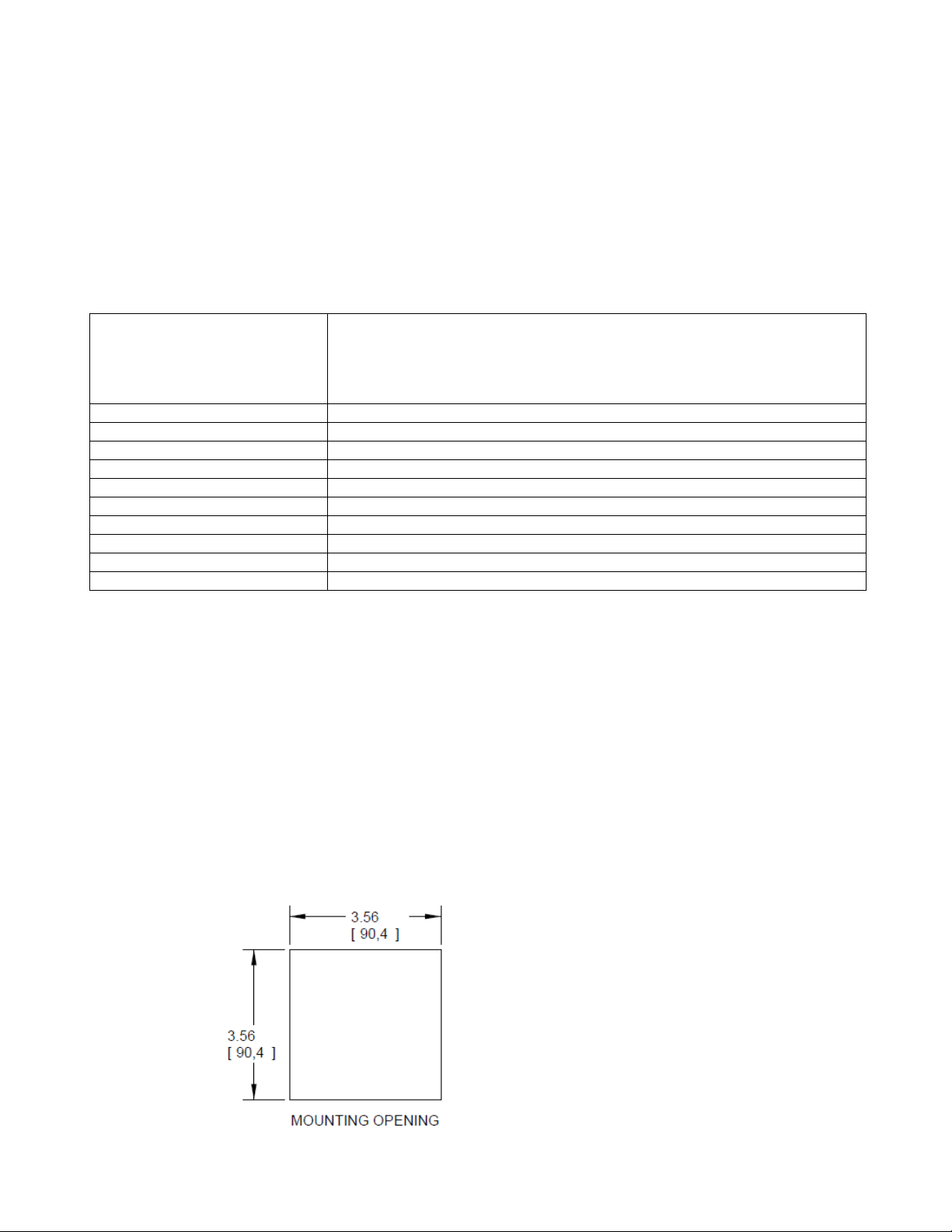
The UM-600 monitor is a standard ¼ DIN package, designed to be panel mounted. The
cutout dimensions are shown below.
3
Page 5
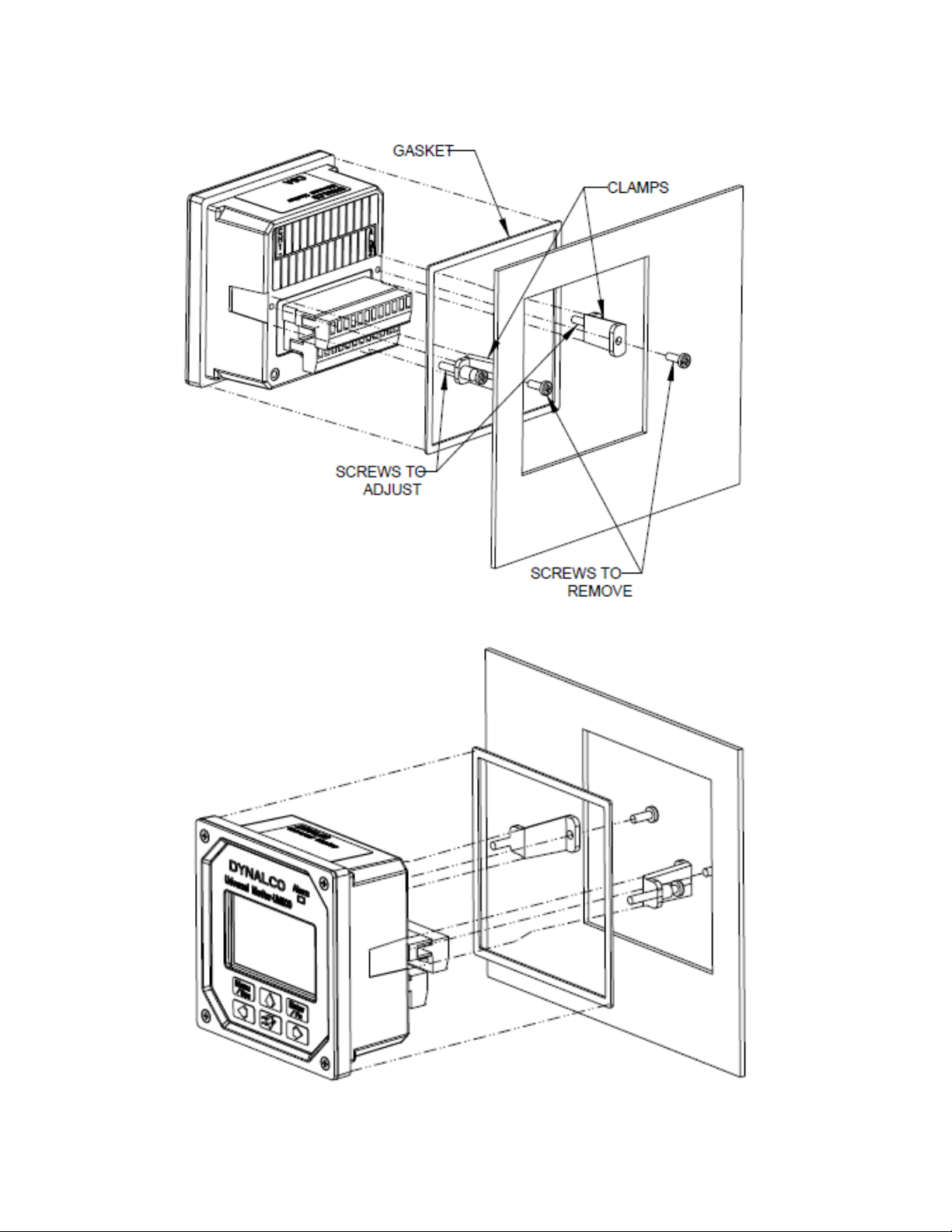
The UM-600 has integral mounting clips for securing into the panel. The following drawings
illustrate the mounting procedure.
4
Page 6
Terminal Connections
PIN
Description
PIN
Description
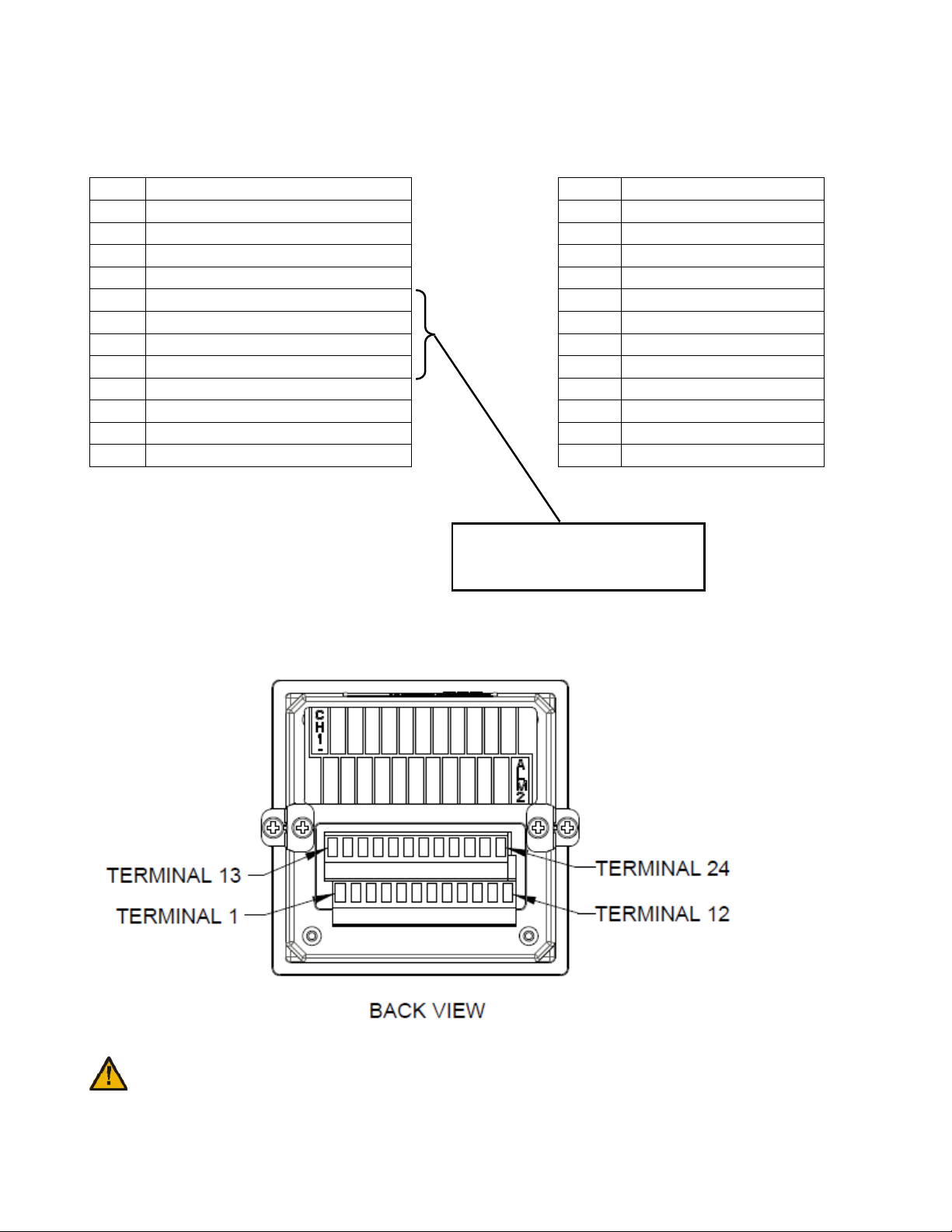
All connections are made via the removable connectors on the back of the unit.
1 GND (Power Gnd) 13 Channel 1 (-)
2 VIN (10 – 36 VDC input) 14 Channel 1 (+)
3 GND (mag pickup input) 15 Channel 2 (-)
4 RPM + (mag pickup input) 16 Channel 2 (+)
5 Receive Data (-) 17 Channel 3 (-)
6 Receive Data (+) 18 Channel 3 (+)
7 Transmit Data (-) 19 Channel 4 (-)
8 Transmit Data (+) 20 Channel 4 (+)
9 Alarm 1 21 Channel 5 (-)
10 Alarm 1 22 Channel 5 (+)
11 Alarm 2 23 Channel 6 (-)
12 Alarm 2 24 Channel 6 (+)
Also used for USB download
cable assembly p/n 270A-13020
(see page 15)
See page 21 for complete wiring information.
Terminal screws to be tightened to 4 inch-pounds torque.
5
Page 7
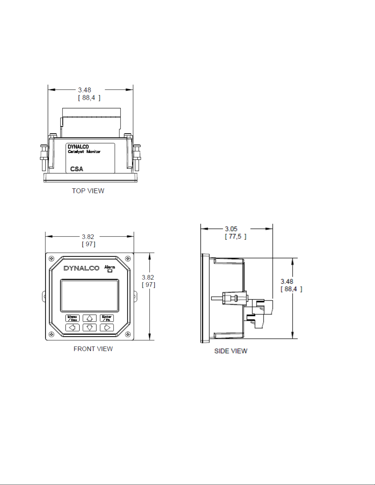
Outline Dimensions
6
Page 8

Programming Overview
All programming is accomplished through the front keypad. Below is a brief description of
each key.
Press to enter or exit the configuration screens
Press to enter or accept values
Select up
Select down
Go back one screen
Select and advance to next screen
Configuration consists of the following steps:
1) Setting current date / time
2) Enabling each input
3) Defining each input type
4) Defining min. & max. display values for any current or voltage inputs
5) Defining measurement display units (PSI, mV, F, C, H20, etc)
6) Setting over / under setpoint trips
7) Selecting either output 1 or output 2 (or both) for alarm trips
8) Setting either latching or non-latching for output trips
9) Defining data logging events
7
Page 9

Programming Instructions
Important: The UM-600 universal monitor must first be programmed prior to operation.
When first powering up the unit, the display will first indicate the firmware version and then go
to the operational mode. It may also display a screen warning that the time & date need to be
entered. This will be explained below.
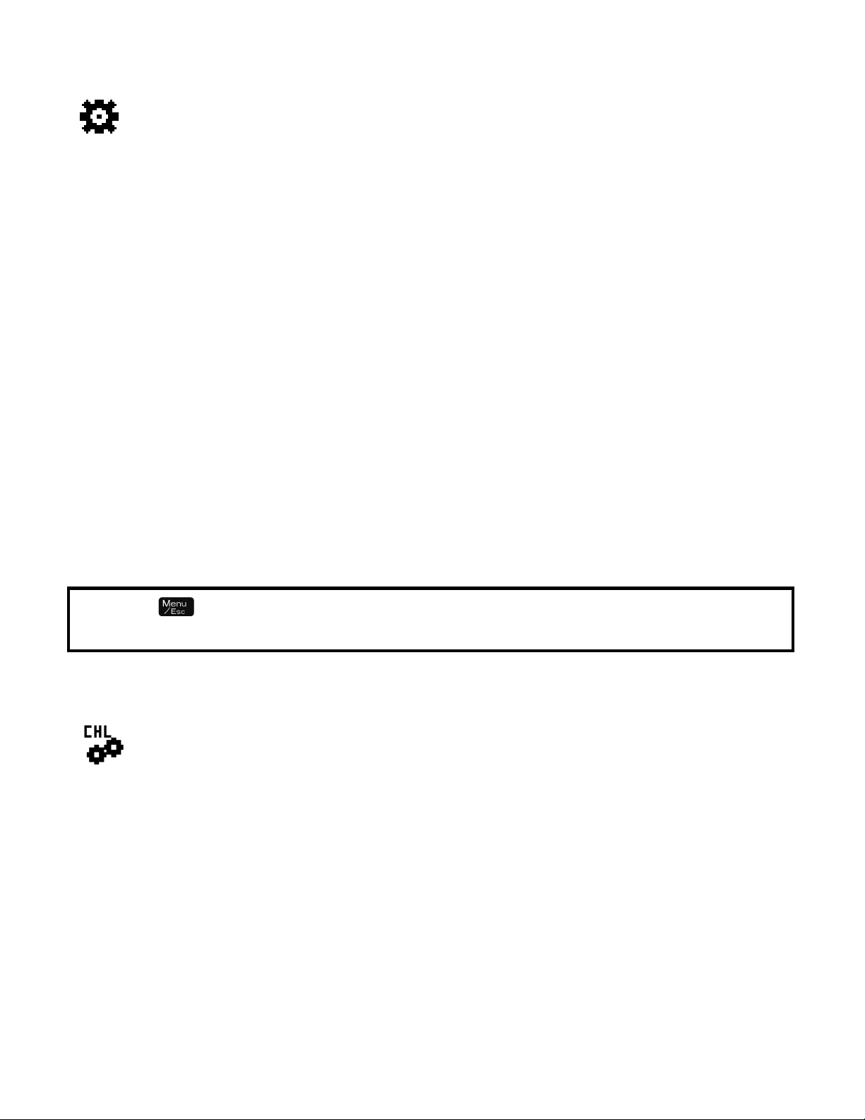
To configure the UM-600 Monitor, first go to the main programming screen by pressing the
Menu / Escape key:
The following menu icons will appear from left to right:
Run Signal - defines run status input type (if any)
Channel - enables each channel type and alarm thresholds
Calibration - defines zero & span values for DCV & mA inputs
Alarm Settings - for setting high /low alarm thresholds
Alarm Logs - allows the user to view alarm status
Communication - Log Reader / Modbus setup
Data Logging - allows configuration of up to (10) different logging events
System - allows display customization & current date / time input
8
Page 10
A description of each menu item follows:
“Run Signal”
There are (3) run types available. The definitions are as follows:
None: No run indication required. Monitoring is always active.
RPM: Monitoring is active when signal received from magnetic pickup.
Digital: Monitoring is active when contact closure (connection to ground) is sensed.
To select run signal type, use the up / down arrows to select, then press the right arrow to
accept and advance to the next screen.
If “None” is selected, there is no other action required other than to select “escape.” After
selecting escape, you will be asked to select “yes” to save.
If “RPM” is selected, you will need to set the # gear teeth, RPM threshold and startup delay.
The RPM threshold is the speed above which monitoring will be active. The startup delay can
be configured to delay monitoring if desired, allowing time for all inputs to be at normal levels.
If no delay is required, set to 0 seconds. The magnetic pickup input terminals are indicated on
page 5.
If “Digital” is selected, you will only need to set the startup delay (if applicable). In this mode,
a run signal will be sensed with a contact closure (or short) between the magnetic pickup
input terminals indicated on page 5.
Pressing at any time during configuration will prompt you to save the changes.
Select “Yes” to save any changes made. Selecting “No” will not save changes.
“Channel”
Select the channel number to configure by pressing the up / down arrows, then pressing the
right arrow to navigate and select the following:
Enable Channel Yes / No
Channel Type 0-1 V, 0-5 V, 0-10 V, 4-20 mA, J Type, K Type
Description name input with up to 20 characters
Engineering Units up to 3 characters, for example: PSI, mV, F, C etc…
Note: For thermocouple inputs, you must enter either “F” or “C”
Differential calculations between channels 1&2, 3&4, 5&6 are also enabled by selecting the
“Channel” icon. Enable “Differential 1” for channels 1&2, “Differential 2” for channels 3&4 and
“Differential 3” for channels 5&6.
9
Page 11

10
”Calibration”
Select the channel number to configure by pressing the up / down arrows and
pressing the right arrow to select and continue.
The screens allow you to define the “Cal Zero” and “Cal Span” values for any channels that
are configured for 0-1 V, 0-5 V, 0-10 V or 4-20 mA inputs.
Example
A pressure transmitter is connected to channel # 1. The transmitter has a 4-20 mA
output representing a pressure input of 0 - 500 PSI. The “Cal Zero” and “Cal Span”
values would be defined as:
Cal Zero = 0
Cal Span = 500
Note that the “Engineering Units” would be input as PSI in “Channel” configuration
above.
“Alarm Settings”
Select the channel number to configure by pressing the up / down arrows, then pressing the
right arrow to navigate and select the following:
Enable alarms Yes / No
Alarm Type Latching / Non-Latching
Alarm Output None / Output 1 / Output 2 / Output 1 and 2
Alarm Low threshold for under-trip
Alarm High threshold for over-trip
Alarm Reset Points Set Defaults / Set Manually
If “Set Manually” is selected, 2 more screens follow:
Alarm Reset Low manually set reset hysteresis for low trip
Alarm Reset High manually set reset hysteresis for high trip
“Alarm Logs”
Selecting the “Alarm Logs” icon will allow you to view any active alarms as well as the history
log for each channel. Select any channel number by pressing the up / down arrows. Then
press the right arrow to view any active or logged alarms. Once an active alarm is
acknowledged, it will be placed into the history log. The history log will continuously store the
last 10 alarms for each channel as well as the time & date of each alarm occurrence.
“Communication”
This allows configuration for downloading data and Modbus communications.
Page 12

11
”Data Logging”
The UM-600 can be configured to log any of the parameters being monitored, at user defined
time intervals. The values are saved to an internal flash memory with sufficient memory to
hold up to 500,000 data values with date / time stamps. These values can be downloaded at
any time to a PC using Dynalco’s “Log Reader” software.
The logging of any parameter is configured as an event. The UM-600 will allow up to (10)
individual events to be defined.
Example # 1:
To configure data logging of an input value every 5 minutes:
Using the arrows on the keypad, select the “Data Logging” icon.
Next, select “Setup Log Events” and press the arrow.
The next screen will display a list of (10) events that can be configured. If this is the first event
to be programmed, select “Event 1” and press the arrow.
Next select “Enable” and press the arrow.
The next screen allows you to define an “On” condition. In most cases this will not be needed
since the “On” condition is normally defined by an “engine run” signal. See above (page 9) for
the procedure for configuring the “run” signal. In this example, select “No” and press the
arrow.
The next screen named “Input To Log” allows the user to select which parameter to log.
Using the up / down arrows, select the input channel that is to be logged. Press arrow.
The next screen named “Log Frequency” allows the configuration of how often (in minutes)
the value is to be logged. Press enter and edit for 5 minutes. Selecting escape will return
to the “Log Frequency” screen. Press the arrow and then select “Yes” to save the
changes. Pressing the escape key two times will escape to the normal monitoring mode.
Page 13

12
Example # 2:
To configure data logging of an input value following engine warm up:
(Note that this configuration will require an input signal from a magnetic pickup to indicate
engine running.)
Using the arrows on the keypad, select the “Data Logging” icon.
Next, select “Setup Log Events” and press the arrow.
The next screen will display a list of (10) events that can be configured. If this is the second
event to be programmed, select “Event 2” and press the arrow.
Next select “Enable” and press the arrow.
The next screen allows you to define an “On” condition. The configuration for logging this
value will require an “On” condition defined by an “engine run” signal. See above (page 9) for
the procedure for configuring the “run” signal. In this case, select “Yes” and press the
arrow.
Select “Edit Compare” on the next screen and press the arrow.
Select “Compare 1” on the next screen and press the arrow.
Select “RPM” on the next screen and press the arrow.
Select “Greater Than” on the next screen and press the arrow.
Select “A Value” on the next screen and press the arrow.
On the following screen, select an RPM value that will indicate engine running. This value
should be lower than the normal engine running speed and higher than the RPM defined as
the “run” signal in page 9.
The next screen will ask if you want to “Edit Another?” Select “no” and press the arrow.
Press the arrow (3) more times until the screen appears as “Enter ON Delay.” Enter this
number as the time delay (in seconds) following engine start when you would like to log the
input value. The maximum value configurable is 3600 seconds (60 minutes.) After entering
the time delay, press arrow.
The next screen allows you to define an “Off” condition. In this case, select “No” and press
the arrow.
The next screen named “Input To Log” allows the user to select which parameter to log.
Using the up / down arrows, select the input to log and press arrow.
The next screen named “Log Frequency” allows the configuration of how often (in minutes)
the value is to be logged. Entering 0 minutes will allow only (1) data log event following the
Page 14

13
start delay. If you wanted to continuously log the value, you would select the frequency in
minutes between data logs. Selecting escape will return to the “Log Frequency” screen.
Press the arrow and then select “Yes” to save the changes.
Pressing the escape key two times will escape to the normal monitoring mode.
“System”
“Display defaults” allows the selection of either single channel (absolute) or differential value
display. Note that regardless of this setting, pressing the right or left arrow during normal
operation will display the alternate display type.
“Digital output” allows the configuration of the solid state relay alarm outputs as either
“Normally Open” or “Normally Closed”
“Set date and time” is self-explanatory but is important for proper date / time stamps for both
alarm logs and data logging.
IMPORTANT NOTICE REGARDING CORRECT DATE / TIME SETTING:
The correct date / time is imperative for proper data logging.
Please note that the date and time may need to be re-programmed if the UM-600 Monitor
loses input power for over 1 week. This will be indicated by a warning upon powering up the
unit.
Note that only the date / time may be affected by extended loss of power. Any data logged to
the internal flash memory will be held indefinitely.
Page 15
14
Alarm Outputs
The UM-600 will alarm when channel values or differential values are above or below limits
as specified. Alarms can be configured as either latching or non-latching. If an alarm
condition is met, the red LED on the front panel will blink and the digital output(s) will trip. The
alarm point name (ch1, ch2, df1, df2) that caused the alarm will be stored in memory with
date/time stamp info. Non-latching alarms will reset the alarm if its value returns to normal.
Latching alarms require manual resetting via the front keypad.
WARNING:
The alarm / shutdown output should be tested monthly for proper operation, especially
if being used for engine overspeed shutdown or other critical function.
IMPORTANT NOTICE REGARDING POWER INTERRUPTION:
If input power to the UM-600 Monitor is disconnected or lost during a data log operation,
there is the possibility of losing data (see page 2).
To prevent this, it is important to turn off the data logging prior to power disconnect. This is
accomplished through the “Data Logging” icon on the main menu. When this is selected, the
first screen will allow you to select “Stop Logging.” Pressing the
arrow will provide
instructions for a safe power down.
The data logging will be enabled automatically when power is re-applied.
Page 16

15
Downloading logged values to PC:
The hardware connection from the UM-600 Monitor to a PC is via a USB cable assembly,
Dynalco p/n 270A-13020. The 6 ft cable length allows easy connection via a 4 pin Phoenix
plug to the lower connector (terminals 5, 6, 7, 8) on the back of the UM-600 Monitor. When
initially plugging the download cable into the PC’s USB port, the new device should be
recognized and the driver installed automatically.
Please call (954) 739-4300 if the driver is not installed properly or assistance is required.
The Dynalco host software “LogReader” is available as a free download from our website:
www.dynalco.com/downloads
There are (2) versions available:
LogReader Ver. 1 Use for Version 1 UM-600
LogReader ver. 2 Use for Version 2 UM-600
Following installation, you may click on the icon to open the application. This software will
allow date selectable log values to be downloaded to an excel spread sheet on the PC.
Page 17

16
Modbus Communication
PIN
Description
The unit also provides access to the internal registered values using the Modbus Protocol.
The diagram below shows the recommended connections to the removable connectors on
the back of the unit for either half-duplex or full-duplex (RS485).
Wiring is as follows:
5 TD(A) **
6 TD(B) **
7 Jumper to PIN 5
8 Jumper to PIN 6
** A 120 ohm termination resistor may need to be installed across pins 5 & 6.
Page 18

17
Modbus Address Registers:
Modicon
Modbus
Description
Min Value
Max
Data type
300001
0
Status Register, 0=not running,
0 1 16 bit signed integer
300002
1
Reserved
-32768
32768
16 bit signed integer
300003
2
Alarms
Bit mask
Bit 0
- Channel 1 Alarm
0 1
0001h
Bit 1
- Channel 2 Alarm
0 1
0002h
Bit 2
- Channel 3 Alarm
0 1
0004h
Bit 3
- Channel 4 Alarm
0 1
0008h
Bit 4
- Channel 5 Alarm
0 1
0010h
Bit 5
- Channel 6 Alarm
0 1
0020h
Bit 6
- Channel 1
-
2 Differential
0 1 0040h
Bit 7
- Channel 3
-
4 Differential
0 1 0080h
Bit 8
- Channel 5
-
6 Differential
0 1 0100h
Bit 9
- reserved
0 1
0200h
Bit 10
- reserved
0 1
0400h
Bit 11
- reserved
0 1
0800h
Bit 12
- reserved
0 1
1000h
Bit 13
– reserved
0 1
2000h
Bit 14
– reserved
0 1 4000h
Bit 14
– reserved
0 1
8000h
300004
3
Channel 1 Value
-32768
32767
16 bit signed integer
300005
4
Channel 2 Value
-32768
32767
16 bit signed integer
300006
5
Channel 3 Value
-32768
32767
16 bit signed integer
300007
6
Channel 4 Value
-32768
32767
16 bit signed integer
300008
7
Channel 5 Value
-32768
32767
16 bit signed integer
300009
8
Channel 6 Value
-32768
32767
16 bit signed integer
300010
9
Channel 1 and 2 Differential Value
-32768
32767
16 bit signed integer
300011
10
Channel 3 and 4 Di
fferential Value
-32768
32767
16 bit signed integer
300012
11
Channel 5 and 6 Differential Value
-32768
32767
16 bit signed integer
300013
12
Channel 1 High Alarm Limit
-32768
32767
16 bit signed integer
300014
13
Channel 2 High Alarm Limit
-32768
32767
16 bit signed integer
300015
14
Channel 3 High Alarm Limit
-32768
32767
16 bit signed integer
330016
15
Channel 4 High Alarm Limit
-32768
32767
16 bit signed integer
The Modbus address registers are defined in the tables below.
Input Register Table (table 1)
Address
Offset
Value
1=running.
Alarm
Alarm
Alarm
Page 19

18
300017
16
Channel 5 High Alarm Limit
-32768
32767
16 bit signed integer
300018
17
Cha
nnel 6 High Alarm Limit
-32768
32767
16 bit signed integer
330019
18
Channel 1 and 2 Differential High
Alarm Limit
-
32768
32767
16 bit signed integer
300020
19
Channel 3 and 4 Differential High
-
32768
32767
16 bit signed integer
300021
20 Channel 5 and 6 Differential High
-
32768
32767
16 bit signed integer
300022
21
Channel 1 Low Alarm Limit
-32768
32767
16 bit signed integer
300023
22
Channel 2 Low Alarm Limit
-32768
32767
16 bit signed integer
300024
23
Channel 3 Low Alarm Li
mit -
32768
32767
16 bit signed integer
300025
24
Channel 4 Low Alarm Limit
-32768
32767
16 bit signed integer
300026
25
Channel 5 Low Alarm Limit
-32768
32767
16 bit signed integer
300027
26
Channel 6 Low Alarm Limit
-32768
32767
16 bit signed integer
300028
27
Channel 1 and 2 Differential Low
-
32768
32767
16 bit signed integer
300029
28
Channel 3 and 4 Differential Low
-
32768
32767
16 bit signed integer
300030
29
Channel 5 and 6 Differential Low
-
32768
32767
16 bit
signed integer
300031
30
RPM
0
65535
16 bit unsigned integer
300032
31
Register Table Version
0
65535
16 bit unsigned integer
301002
-
1001
-
Log Buffer Entry #1
Custom (See table 4)
301006
-
1005
-
Log Buffer Entry #2
Custom (
See table 4)
301010
-
1009
-
Log Buffer Entry #3
Custom (See table 4)
301014
-
1013
-
Log Buffer Entry #4
Custom (See table 4)
301018
-
1017
-
Log Buffer Entry #5
Custom (See table 4)
301022
-
1021
-
Log Buff
er Entry #6
Custom (See table 4)
301026
-
1025
-
Log Buffer Entry #7
Custom (See table 4)
301030
-
1029
-
Log Buffer Entry #8
Custom (See table 4)
301034
-
1033
-
Log Buffer Entry #9
Custom (See table 4)
301038
-
1037
-
Log Buffer Entry #10
Custom (See table 4)
301042
-
1041
-
Log Buffer Entry #11
Custom (See table 4)
Alarm Limit
Alarm Limit
Alarm Limit
Alarm Limit
Alarm Limit
301005
301009
301013
301017
301021
301025
301029
301033
301037
301041
1004
1008
1012
1016
1020
1024
1028
1032
1036
1040
301045
1044
Page 20

19
301046
-
301049
1045
-
Log Buffer Entry #12
Custom (See table 4)
301050
-
1049
-
Log Buffer Entry #13
Custom (See table 4)
301054
-
1053
-
Log Buffer Entry #14
Custom (See table 4)
301058
-
1057
-
Log Buffer Entry #15
Custom (See table 4)
301062
-
1061
-
Log Buffer Entry #16
Custom (See table 4)
301066
-
1065
-
Log Buffer Entry #17
Custom (See table 4)
301070
-
1069
-
Log Buffer Entry #18
Custom (See table 4)
301074
-
1073
-
Log Buffer Entry #19
Custom (See table 4)
301078
-
1077
-
Log Buffer Entry #20
Custom (See table
4)
301082
-
1081
-
Log Buffer Entry #21
Custom (See table 4)
301086
-
1085
-
Log Buffer Entry #22
Custom (See table 4)
301090
-
1089
-
Log Buffer Entry #23
Custom (See table 4)
301094
-
1093
-
Log Buffer Ent
ry #24
Custom (See table 4)
301098
-
1097
-
Log Buffer Entry #25
Custom (See table 4)
301102
-
1101
-
Log Buffer Entry #26
Custom (See table 4)
301106
-
1105
-
Log Buffer Entry #27
Custom (See table 4)
301110
-
1109
-
Log Buffer Entry #28
Custom (See table 4)
301114
-
1113
-
Log Buffer Entry #29
Custom (See table 4)
301118
-
1117
-
Log Buffer Entry #30
Custom (See table 4)
302002
-
2001
-
Channel 1 Float Value
-9999.0
99999.0
32 bit Float(IEEE 754)
302004
-
2003
-
Channel 2 Float Value
-9999.0
99999.0
32 bit Float(IEEE 754)
1048
301053
301057
301061
301065
301069
301073
301077
301081
301085
301089
1052
1056
1060
1064
1068
1072
1076
1080
1084
1088
301093
301097
301101
301105
301109
301113
301117
301121
302003
302005
1092
1096
1100
1104
1108
1112
1116
1120
2002
2004
Page 21

20
302006
-
302007
2005
-
Channel 3 Float Value
-9999.0
99999.0
32 bit Float(IEEE 754)
302008
-
2007
-
Channel 4 Float Value
-9999
.0 99999.0
32 bit Float(IEEE 754)
302010
-
2009
-
Channel 5 Float Value
-9999.0
99999.0
32 bit Float(IEEE 754)
302012
-
2011
-
Channel 6 Float Value
-9999.0
99999.0
32 bit Float(IEEE 754)
302014
-
2013
-
Channel 1 and 2 Different
ial Value
-9999.0
99999.0
32 bit Float(IEEE 754)
302016
-
2015
-
Channel 3 and 4 Differential Value
-9999.0
99999.0
32 bit Float(IEEE 754)
302018
-
2017
-
Channel 5 and 6 Differential Value
-9999.0
99999.0
32 bit Float(IEEE 754)
302020
-
2019
-
Channel 1 High Alarm Limit
-9999.0
99999.0
32 bit Float(IEEE 754)
302022
-
2021
-
Channel 2 High Alarm Limit
-9999.0
99999.0
32 bit Float(IEEE 754)
302024
-
2023
-
Channel 3 High Alarm Limit
-9999.0
99999.0
32 bit Float(IE
EE 754)
302026
-
2025
-
Channel 4 High Alarm Limit
-9999.0
99999.0
32 bit Float(IEEE 754)
302028
-
2027
-
Channel 5 High Alarm Limit
-9999.0
99999.0
32 bit Float(IEEE 754)
302030
-
2029
-
Channel 6 High Alarm Limit
-9999.0
99999.
0 32 bit Float(IEEE 754)
302032
-
2031
-
Channel 1 and 2 Differential High
-
9999.0
99999.0
32 bit Float(IEEE 754)
302034
-
2033
-
Channel 3 and 4 Differential High
-
9999.0
99999.0
32 bit Float(IEEE 754)
302036
-
2035
-
Channel 5 and 6 Differential High
-
9999.0
99999.0
32 bit Float(IEEE 754)
302038
-
2037
-
Channel 1 High Low Limit
-9999.0
99999.0
32 bit Float(IEEE 754)
302040
-
2039
-
Channel 2 High Low Limit
-9999.0
99999.0
32
bit Float(IEEE 754)
302042
-
2041
-
Channel 3 High Low Limit
-9999.0
99999.0
32 bit Float(IEEE 754)
302044
-
2043
-
Channel 4 High Low Limit
-9999.0
99999.0
32 bit Float(IEEE 754)
302046
-
2045
-
Channel 5 High Low Limit
-9999.0
99999.0
32 bit Float(IEEE 754)
2006
302009
302011
302013
302015
302017
302019
302021
302023
302025
302027
2008
2010
2012
2014
2016
2018
2020
2022
2024
2026
302029
302031
302033
302035
302037
302039
302041
302043
302045
302047
2028
2030
2032
2034
2036
2038
2040
2042
2044
2046
Alarm Limit
Alarm Limit
Alarm Limit
Page 22

21
302048
-
302049
2047
-
Channel 6 High Low Limit
-9999.0
99999.0
32 bit Float(IEEE 754)
302050
-
2049
-
Channel 1 and 2 Differential Low
-
9999.0
99999.0
32 bit Float(IEEE 754)
302052
-
2051
-
C
hannel 3 and 4 Differential Low
-
9999.0
99999.0
32 bit Float(IEEE 754)
302054
-
2053
-
Channel 5 and 6 Differential Low
-
9999.0
99999.0
32 bit Float(IEEE 754)
302056
-
2055
-
RPM
0
99999.0
32 bit unsigned integer
302058
-
2057
-
Hourmeter
0
99999.0
32 bit unsigned integer
Modicon
Modbus
Description
Min
Max
Data type
401001
-
1000
-
1001
Log start date (upper 16 bits
Custom (See table 3)
32 bit Float(IEEE 754)
2048
302051
302053
302055
302057
302059
Holding Register Table (table 2)
Address
2050
2052
2054
2056
2058
Offset
Alarm Limit
Alarm Limit
Alarm Limit
Value
Value
401002
Date Format Table (table 3)
Second(MSB) Minute Hour
6
Bits
Value
range
0-59
Log Buffer Entry (table 4)
Length
Value
range
Datetime
32 bit unsigned
integer
See table 3
and lower 16 bits
respectively)
6
0-59
5
0-23
Event ID
16 bit unsigned
integer
1-10
Day
5
1-31
Value
-9999.0 – 99999.0
Month
4
1-12
Year(LSB)
6
0-63(relative to year
2000)
Page 23

22
 Loading...