


AF900PC
Air/Fuel Ratio Control System
Installation and Operating Guide
(c) Copyright 2003, Dynalco Controls
All Rights Reserved.
Revision E 01/30/2012
Specifications and information herin are subject to change without notice. Dynalco reserves the right to make changes to the equipment described herin to improve function or design. Although the information contained in this manual has been carefully reviewed and is believed to be reliable, Dynalco does not assume any liability for special, indirect, incidental, or consequential damages arising out of the application or use of the equipment described herein. Warranty is limited and cannot exceed the price paid for the product upon which the warranty is based.
Trademarks
AF900PC, Dynahost, Dynatrend and Dynalink are trademarks of Dynalco. Windows and Windows XP are registered trademarks of Microsoft Corporation.
Dynalco
5450 N.W. 33rd Avenue, Suite 104 Fort Lauderdale, FL 33309 U.S.A. Phone (954) 739-4300
Fax (954) 486-4968 www.dynalco.com
P/N 145F-11993
Rev. E
Dated: January 30, 2012
1
CONTENTS
1. |
Introduction to the AF900PC |
Pg. 3 |
|
2. |
Theory of Operation |
Pg. 3 |
|
3. |
System Diagram |
Pg. 4 |
|
4. |
Specifications |
Pg. 5 |
|
5. |
Components/Installation Summary |
Pg. 6 |
|
|
5.1 |
System Components |
Pg. 6 |
|
5.2 |
Installation Summary |
Pg. 6 |
6. |
Installation Details |
Pg. 7 |
|
|
6.1 |
Mounting the AF900PC Controller |
Pg. 7 |
|
6.2 |
Mounting the Heated Oxygen Sensor(s) |
Pg. 8 |
|
6.3 |
Installation of the K type thermocouple |
Pg. 8 |
|
6.4 |
Installation of M201 Magnetic Pickup for Speed Sensing |
Pg. 8 |
|
6.5 |
Installation of full-authority fuel valves |
Pg. 9 |
7. |
Wiring the AF900PC Controller |
Pg. 9 |
|
8. |
Electrical Connections |
Pg. 9 |
|
9. |
Front Panel Display User Interface |
Pg. 12 |
|
|
9.1 |
Front Panel Configuration Screens |
Pg. 12 |
|
9.2 |
FPD Keypad |
Pg. 13 |
|
9.3 |
FPD Screens |
Pg. 14 |
|
9.4 |
Navigational Map of RUN Screens |
Pg. 15 |
|
9.5 |
Navigational Map of SETUP Mode Screens |
Pg. 16 |
|
9.6 |
FPD SETUP Mode |
Pg. 17 |
10. |
Computer Interface using DynaHost Software |
Pg. 19 |
|
|
10.1 |
Control Panel Specifications |
Pg. 19 |
|
10.2 |
Screen Navigation |
Pg. 20 |
|
10.3 |
Main Screen Specifications |
Pg. 23 |
|
10.4 |
Communication Settings Dialogue |
Pg. 37 |
11. |
Computer Interface using Configuration File |
Pg. 38 |
|
|
11.1 |
Downloading a Configuration File |
Pg. 39 |
|
11.2 |
Uploading Configuration to an .spc file |
Pg. 40 |
12. |
Software Operation |
Pg. 41 |
|
|
12.1 |
AUTO Mode |
Pg. 41 |
|
12.2 |
MANUAL Mode |
Pg. 42 |
13. |
Control Software |
Pg. 42 |
|
14. |
Manifold Air Pressure (MAP) Load Compensation |
Pg. 43 |
|
15. |
Catalytic Converter Delta Temperature |
Pg. 45 |
|
16. |
Data Logging |
Pg. 45 |
|
17. |
Setup |
|
Pg. 46 |
18. |
Transfer |
Pg. 47 |
|
19. |
Start Up Procedure |
Pg. 49 |
|
20. |
Diagnostics |
Pg. 50 |
|
21. |
Appendix A. - Example of a Configuration File |
Pg 52 |
|
22. |
Modbus Addresses |
Pg. 104 |
|
2
1. Introduction to the AF900PC
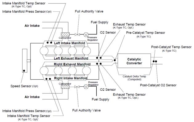
The AF-900PC is a state-of-the-art air/fuel ratio control system for single/dual bank, spark-ignited, natural gas fueled carbureted engines. The AF-900PC incorporates an extensive suite of advanced features that intelligently compensate for real-world sensor and engine conditions.
This sophisticated system maintains the percentage of oxygen (O2) in the engine’s exhaust gas stream by adjusting the amount of fuel to the carburetor(s). Fuel valves mounted between the regulator and carburetor adjust the fuel pressure applied to the carburetor to maintain the desired air/fuel ratio. The AF900PC is designed to work with rich-burn engine systems using 3-way or NSCR type catalytic converters.
In these applications it is very important to maintain air/fuel ratio to avoid damage to the converter, prevent engine damage when fuel BTU content variations cause the engine to run very rich or lean, and ultimately enable the engine to reduce emissions.
2. Theory of Operation
Utilizing heated O2 sensor(s) in the exhaust stream (one per bank), the AF-900PC provides PWM outputs to full-authority fuel valves in order to accurately control air/fuel ratio over a wide load range. The O2 sensor operates best slightly rich or lean of a point called stoichiometric, which is an A/F ratio of 16.09:1 for natural gas.
Engines with catalytic converters should be run slightly rich of stoichiometric for lowest emissions.
The AF900PC implements compensation through an intelligent closed-loop algorithm which provides smooth control behavior that is adaptable to changing engine load, speed, fuel quality, ambient temperature and catalytic converter conditions.
In addition, the AF900PC offers optional intake manifold pressure sensor(s) capability for further adjustment of the post-catalytic setpoints, allowing the catalytic converter to maintain emissions over an even wider range of engine loads and operating conditions.
The AF900PC system monitors the proper operation of all sensor inputs and controller outputs, flagging errors and changing its operating mode when a fault is detected.
Equipped with a powerful onboard data logging feature and real-time clock, the AF900PC has the ability to log controller conditions at either pre-determined times of day or on a time interval basis. This allows users to automatically capture and store diagnostic errors and overall system performance internally over any given period of time. It also aids in troubleshooting hard to catch intermittent system problems.
The MODBUS communications capability allows remote monitoring of system performance and status.
3. System Diagram
AF900PC
Engine Diagram
4
4. Specifications
Inputs |
Left Bank O2 Sensor (heated) |
|
Right Bank O2 Sensor (heated) |
|
RPM Input (Magnetic Pickup) |
|
RPM Status (Contact Closure) |
Controller |
Left Bank Output (PWM) |
Outputs |
Right Bank Output (PWM) |
Relay |
3 Relays, SPDT, rated @ 5A/24VDC, 1A/120VAC, and |
Outputs |
0.5A/220VAC |
Input Power |
10 – 30 VDC @ 70 Watts Input Power to AF900PC controller |
|
|
Sensor Power Out |
+ 8 VDC Active Magnetic Pickup Sensor Power |
|
|
Display |
Backlit, 4 Line x 20 Character Alphanumeric Display with large |
|
0.36” Characters |
|
|
Data Logging |
Internal 64M Flash Memory and Windows Based DynaTrend |
|
Software to transfer the data to a laptop for viewing and graphing |
Communications |
Hardware: RS-232 / RS-485 |
|
Software: DynaHost Laptop Configuration |
|
Modbus |
Connections |
All Two-Part Terminal Blocks |
Operating Temperature |
- 30 to + 80 Deg C |
Range |
|
Certification |
CSA Class I, Division 2, Groups A, B, C, D |
|
|
5

5. Components/Installation Summary
5.1 System Components
Included |
|
Single Bank |
Dual Bank |
|
|
||
AF-900PC-3F |
Air/Fuel Ratio Controller |
(1) |
(1) |
400A-12959 |
Pre-Cat O2 Sensor Cable Ass’y (50 ft) |
(1) |
(2) |
400A-12064 |
Post-Cat O2 Sensor Cable Ass’y (100 ft) |
(1) |
(1) |
External Components (purchase separately) |
|
|
|
Heated Pre-Cat Oxygen Sensor (Bosch p/n 15718) |
(1) |
(2) |
|
Full-Authority Fuel Valve |
(1) |
(2) |
|
Optional External Components (purchase separately) |
|
|
|
M201 |
Magnetic Pickup for speed sensing |
(1) |
(1) |
C101-XX |
Pickup Cable for M201 |
(1) |
(1) |
Heated Post-Cat Oxygen Sensor (Bosch p/n 15718) |
(1) |
(1) |
|
K type thermocouples (ungrounded) |
(2) |
(2) |
|
5.2 Installation Summary
1.Mount AF900PC Controller
2.Install Oxygen Sensor(s) in each engine exhaust bank
3.Run cables for Oxygen Sensors to controller (conduit must be used for Division 2 certification).
4.Install full-authority fuel valve(s)
5.Wire power to controller (10-30 VDC)
6.Install pickup for engine run signal and wire to controller. (Note: A contact closure run signal may be used instead of the magnetic pickup).
7.Wire controller Alarm, Shutdown, and Auxiliary relay outputs to engine panel shutdown and warning devices as required.
6
6. Installation Details
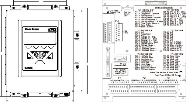
6.1 Mounting the AF900PC Controller
The AF900PC Controller (Fig. 1) should be mounted at “eye level” in an accessible location for easy display and keypad interface. The controller must be mounted in surroundings where vibration is minimal and the ambient temperature does not exceed 80 Deg C. A typical mounting location is on the side of the engine control panel. A shock mount kit should always be used while mounting. All wiring enters the controller through the bottom of the enclosure. There are three holes for ½” conduit entry. All wiring is connected to the main board using removable terminal blocks for ease of wiring and controller replacement.
NOTE: Installation requires four mounting holes.
8.0 |
13.5 |
12.25 |
12.8
10.25 |
Front View |
Inside View |
AF900PC
Air/Fuel Ratio Control System
Fig. 1
7
6.2 Mounting the Heated Oxygen Sensor(s)
The heated oxygen sensor(s) should be mounted in the exhaust pipe as close to the engine exhaust manifold as possible. A single bank engine requires only one sensor. For dual bank “V” engines, the left and right bank sensors should be mounted as close to the engine exhaust manifold as possible to eliminate cross talk between the two banks.
CAUTION: The sensor(s) must be mounted where the temperature on the outer shell does not exceed 400O F (204O C).
Above 400oF, sensor life will deteriorate rapidly and output voltage will be affected. The sensor(s) should be mounted on a horizontal plane or above horizontal to keep water from accumulating on the sensor tip. The sensor(s) should also be mounted where they are accessible as sensor replacement is recommended every 2000 hours. It is recommended a fitting with 18mm x 1 ½ internal threads be welded into the exhaust pipe for each sensor to be mounted. This will provide a flat mounting surface for the sensor to avoid exhaust leaks. Sensors should be mounted with an anti-seize compound on the threads.
NOTE: Recommended torque for mounting the sensors is 28 – 38 ft-lbs.
The conduit for the oxygen sensor should be routed to avoid close proximity to high tensions ignition cables and coils to minimize potential EMI interference. Ignition, flow control valve, and power wiring must not be placed in the same conduit with oxygen sensor wiring. The conduit should also be routed where temperature does not exceed 200oF.
6.3 Mounting the K type thermocouples (ungrounded must be used)
Optional thermocouples may be installed in the exhaust pipe to monitor pre and post catalyst temperatures. The AF900PC will also calculate the differential (or delta) temperature to help ensure proper catalyst operation. An NPT tap should be used to tap the hole for the thermocouple. An adjustable fitting on most thermocouple probes will allow proper insertion depth into the exhaust stream. The thermocouples should be connected to the AF900PC terminal block using thermocouple extension wire to eliminate erroneous readings.
6.4 Installation of M-201 Magnetic Pickup for Speed Sensing
The M201 magnetic pickup detects engine speed by sensing flywheel gear teeth as they pass by. The pickup must be mounted on a bracket or flywheel cover so that it is perpendicular to the face of the flywheel teeth it is sensing. The M201 requires a
5/8-18 UNF thread for mounting. The gap between the pickup pole piece and the gear teeth should be set to 0.020” to 0.030”. Once the gap has been set, the pickup should be secured with the lock nut. The M201 should be connected to the
AF900PC with a C101 pickup cable/connector.
8
6.5 Installation of the full-authority fuel valves (one per bank)
The full-authority fuel valves are to be mounted between the fuel regulator and carburetor fuel inlet, as close to the carburetor inlet as possible.
7. Wiring the AF900PC Controller
All wiring to the AF900PC enters the controller through three (3) conduit openings in the bottom and connects to three (3) double row terminal strips on the bottom of the controller main board. The terminal strips unplug from the main board for ease of controller wiring and replacement. The main board cover plate shows the location of the terminal strips.
Wiring for terminal strip TS1 should enter through the left conduit opening.
Wiring for terminal strip TS2 should enter through the center conduit opening.
Wiring for terminal strip TS3 should enter through the right conduit opening. This will separate the millivolt signal levels on TS1 and TS2 from the power, output, and relay wiring on TS3.
8. Electrical Connections
The Fuel Valves must be configured for single demand, PWM control, and low side drive.
Terminal Strip |
Description |
TS1 |
|
Bottom Row |
|
TS1-1 |
Left Bank Oxygen Sensor Output + |
TS1-2 |
Left O2 Sensor Cable - (Black and Shield) |
TS1-3 |
Right Bank Oxygen Sensor Output + |
TS1-4 |
Right O2 Sensor Cable - (Black and Shield) (DB only) |
TS1-5 |
Post-Catalyst Sensor Cable + (White) |
TS1-6 |
Post-Catalyst Sensor Cable – [Black (paired with white) and shield] |
TS1-7 |
Speed Contact Closure + (Required if speed magnetic pickup is not used) |
TS1-8 |
Speed Magnetic Pickup + |
TS1-9 |
Speed Magnetic Pickup - and shield (for speed contact closure if used) |
9
Terminal Strip |
Description |
TS1 |
|
Top Row |
|
TS1-10 |
Pre-Catalyst Thermocouple + (Yellow) |
TS1-11 |
Pre-Catalyst Thermocouple - (Red) |
TS1-12 |
Post-Catalyst Thermocouple + (Yellow) |
TS1-13 |
Post-Catalyst Thermocouple - (Red) |
TS1-14 |
Left Exhaust Thermocouple + (Yellow) |
TS1-15 |
Left Exhaust Thermocouple - (Red) |
TS1-16 |
Right Exhaust Thermocouple + (Yellow) (DB only) |
TS1-17 |
Right Exhaust Thermocouple - (Red) (DB only) |
TS1-18 |
Not Used |
Terminal Strip |
Description |
TS2 |
|
Bottom Row |
|
TS2-1 |
Not Used |
TS2-2 |
+8 VDC Pickup Power for Active Speed Pickup (Optional) |
TS2-3 |
Left & Right Bank Valve Power Common |
TS2-4 |
Left Manifold Air Temperature (MAT) Thermocouple + (Yellow) (Optional) |
TS2-5 |
Left Manifold Air Temperature (MAT) Thermocouple - (Red) (Optional) |
TS2-6 |
Right Manifold Air Temperature (MAT) Thermocouple + (Yellow) (Optional) |
TS2-7 |
Right Manifold Air Temperature (MAT) Thermocouple - (Red) (Optional) |
TS2-8 |
Left Manifold Air Pressure (MAP) Sensor Input (+) |
TS2-9 |
Left Manifold Air Pressure (MAP) Sensor Input (-) |
TS2-10 |
DC Power for Left and Right Manifold Air Pressure (MAP) Sensors |
|
(Factory set to Input Supply Voltage but jumper selectable to 5.0 VDC) |
TS2-11 |
Right Manifold Air Pressure (MAP) Sensor Input (+) |
TS2-12 |
Right Manifold Air Pressure (MAP) Sensor Input (-) |
Terminal Strip TS2, Top Row
No Connections Currently Used
Terminal Strip |
Description |
TS3 |
|
Bottom Row |
|
TS3-1 |
Left Bank + PWM Valve Position Control |
TS3-2 |
Left Bank Valve +12/24 DC Power |
TS3-3 |
Right Bank + PWM Valve Position Control |
TS3-4 |
Right Bank Valve +12/24 DC Power / Right Bank Oxygen Sensor Heater - |
TS3-5 |
Left & Right Bank Oxygen Sensor Heater - |
TS3-6 |
Left & Right Bank Oxygen Sensor Heater + |
TS3-7 |
Not Used |
TS3-8 |
+10 to 30 VDC System Power In @ 70 Watts (#16 AWG wire required) |
TS3-9 |
DC Power Common (#16 AWG wire required) |
10

Terminal Strip |
|
Description |
TS3 |
|
|
Top Row |
NOTE: Relay contacts are shown in the de-energized state. |
|
TS3-10 |
Alarm Relay |
Common |
TS3-11 |
Alarm Relay |
Normally Closed |
TS3-12 |
Alarm Relay |
Normally Open |
TS3-13 |
Shutdown Relay |
Common |
TS3-14 |
Shutdown Relay |
Normally Closed |
TS3-15 |
Shutdown Relay |
Normally Open |
TS3-16 |
Auxiliary Relay |
Common |
TS3-17 |
Auxiliary Relay |
Normally Closed |
TS3-18 |
Auxiliary Relay |
Normally Open |
This terminal strip contains the contacts for the alarm, shutdown, and auxiliary relays. These contacts are isolated and may be connected to engine shutdown devices (such as the panel annunciator) or warning devices as required. Any of the
AF900PC thirty-nine trip channels may be programmed to energize one of the three relays. The SPDT relay contacts are rated @ 5A/24VDC, 1A/120VAC, and
0.5A/220VAC.
11

9. Front Panel Display User Interface
The AF900PC requires the user to configure a variety of parameters. By performing one of three procedures below, parameters may be configured.
1)Using interface via the SETUP key (password required), keypad, and a 4x20 display.
NOTE: A limited number of parameters are available in the setup screens of the AF900PC. Using a laptop to configure the AF900PC is recommended.
2)Using DynaHost multiple laptop configuration screens via a laptop or PC.
3)Using DynaHost, a text editor (Windows Wordpad) and editing the downloaded file (AF900PC.SPC) via a laptop or PC.
9.1 Front Panel Configuration Screens
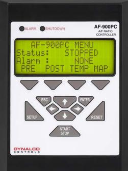
The AF900PC Front Panel Display (FPD) user-interface consists of a 4-row by 20column LCD display (LCD); a 13-key custom keypad; and two LEDs to indicate ALARM and SHUTDOWN.
12
9.2 FPD Keypad
The custom keypad consists of the following keys:
Four screen-specific Soft Keys are located directly under the LCD. These keys navigate to other screens or perform specific actions as indicated in the last line of the LCD.
SETUP Key enters SETUP Mode.
ESC Key navigates up one menu-level; exits SETUP Mode; returns to the Main Title Screen; or cancels certain actions. (Note: To exit SETUP Mode or return to Title Screen, the customer must press and hold the ESC Key for three or more seconds.)
UP, DOWN, LEFT, and RIGHT Keys select or modify values in SETUP Mode.
ENTER Key accepts modified values changed in
SETUP Mode.
RESET Key resets AF900PC fault conditions.
13
9.3 FPD Screens
The LCD displays information to the user, grouping the information into screens. Each screen displays a specific set of information to the user. To change screens, the user must navigate to the desired screen using the indicated Soft Keys.
The AF900PC will display a title screen upon power up.
DYNALCO CONTROLS
AF900PC
V x.yy
The title screen displays a banner and indicates the current software version for five seconds before displaying a main status screen. To return to the title screen, the user must press and hold the ESC key for three seconds.
The main user screens are the Main Status Screen, Pre-Cat Status Screens, PostCat Status Screens, Temperature Screens, and MAP Screen. The main status screen displays the current engine/air-fuel control status (STOPPED, START, MANUAL, AUTO, etc.) and any current ALARM or SHUTDOWN fault conditions.
The pre-cat status screens display the current pre-cat status and fuel valve opening percentage. The post-cat status screen displays the current post-cat status. The temperature screens display all measured engine temperatures. The MAP screen displays the manifold air pressure(s) and engine RPM.
The SETUP mode screens allow authorized operators to view and/or adjust software setpoints.
NOTE: Title Screen is not accessible in SETUP Mode.
A navigational screen map layout for the user RUN screens is shown on page 14.
A navigational screen map layout for the SETUP mode screens is shown on page 15.
14
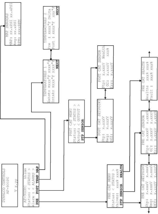
9.4 Navigational Map of RUN Screens
15

9.5 Navigational Map of SETUP Mode Screens
16
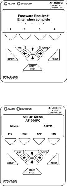
9.6 FPD SETUP Mode
1)To enter SETUP mode, press the SETUP key on the FPD.
2)Enter current SETUP password.
NOTE: A four character default password “1 2 3 4” is pre-assigned prior to shipping. This password may be changed using the DynaHost software to change parameter 6112.0, if desired. Passwords may be up to eight characters in length using the digits 1, 2, 3, or 4 only.
3)Enter password using the Soft Keys labeled “1 2 3 4”. A solid asterisk (*) will appear for each entered character, while a blinking asterisk (*) indicates additional characters may be entered.
4) Press ENTER for SETUP Mode.
17
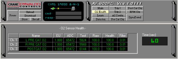
From the SETUP menu the user may navigate to setpoint screens (screens that allow you to change values) by using the Soft Keys. The user may view and/or modify setpoint values as follows:
1.Navigate to the desired setpoint screen.
2.Press the ENTER key to enter setpoint select mode. The first setpoint on the screen is now enclosed in angle brackets, i.e. >SETPOINT<.
3.Press the UP/DOWN keys to select the setpoint to modify. The angle brackets will move from one setpoint to the next for each UP/DOWN key press.
4.Press the ENTER key to enter setpoint modify mode. The bracketed setpoint will blink indicating that the operator may now modify its value.
5.Press the UP/DOWN keys to increment or decrement the setpoint value.
The increment/decrement rate may be changed by selecting the desired rate displayed above the appropriate Soft Key.
6.Press the ENTER key to save the modified setpoint value; press the ESC key to cancel the modified setpoint value and restore the original value.
7.Press the ESC key to exit setpoint select mode and return to SETUP mode screen navigation.
To exit SETUP mode, user must press and hold the ESC key for three seconds. All modified setpoint values will be stored to memory while display shows the following:
CONFIGURATION
PARAMETER STORE
IN PROGRESS
Once the SETUP configuration is stored to memory, the AF900PC returns to the operator screens.
CAUTION: Power must remain normal during the storing process. A failure of power during “In Process” memory storing will result in the loss of all data storage and will bring the AF900PC back to factory defaults.
18

10. Computer Interface using DynaHost Software
DynaHost software provides serial communication between a PC or laptop and the AF900PC. DynaHost will run on a PC with 133MHz Intel Pentium processor, 32
MB of RAM, and a minimum of 100MB of hard disk space. DynaHost is compatible with Windows 95/NT/98/2000/XP.
The AF900PC must be connected via a standard RS-232, 9-pin, male-female, serial communication cable. The HOST software communicates to the AF900PC via Dynalink, Dynalco Control’s ASCII-based serial communication protocol.
When the program is running there are two major sections: the Control Panel and the Current Screen.
10.1 Control Panel Specifications
The Control Panel is located at the top of the application screen on the laptop or PC and allows the user to view the status of the host application, showing the communication settings and status.
Control Panel (Connected)
Figure 1A
The Control Panel above (Fig. 1A) shows an active communication which allows the user to navigate through the multiple screens (Main, O2 Health, Learn, Data log, Trip 1, Trip 2, AI Config, Pre-Cat Cfg, Post-Cat Cfg, RPM Cfg and DynaTrend).
The Control Panel also contains the basic commands:
•Power: Closes the host application.
•Upload: Uploads the current configuration of the AF900PC to a configuration file (.spc).
•Download: Downloads a configuration file (.spc) to the AF900PC.
•Store: Stores the current configuration.
•Recall: Recalls the last configuration stored.
•Cmd: Sends a command to the AF900PC.
•Resp: Shows the response to a command sent to the AF900PC.
•Screen Buttons: Show the current screen being displayed and allows you to switch to other screens.
19
The Control Panel in Fig. B shows an inactive communication by displaying a red
“X” across the communication line.
Control Panel (Disconnected)
Figure 1B
10.2 Screen Description
A yellow highlighted button, as shown in Fig. 1B, displays the current screen you are in. Within each screen you can display information by using the following controls:
Toggle Button: Represents 2-state parameters. Place the mouse over the button to the left of text (Figure 2) to see the current state and click on the button to toggle the state. The button will be green when enabled, black when disabled.
NOTE: The parameter number is displayed when you place the mouse over the label.
(Disabled) (Enabled)
Toggle Button
Figure 2
Read/Write Green Display: A parameter (Figure 3) which may be modified by typing a value and pressing ENTER.
NOTE: The parameter number is displayed when you place the mouse over the label.
Type in value and press <enter>.
Green Display
Figure 3
20

Read Only Blue Display: A parameter (Fig. 4) that can only be read.
Blue Display
Figure 4
Combo Box Display: A parameter (Figure 5) modified by selecting one of the options displayed when you click on the drop-down button.
NOTE: The parameter number is displayed when you place the mouse over the label.
Combo Box Display
Figure 5
Grid Display: A matrix of green displays (Fig. 6). Some parameters may be modified by typing in the value and pressing ENTER (press backspace to delete the current value).
Grid Display
Figure 6
21

Scope: Traces the value of up to two numeric parameters in real time domain. The user may select parameters to trace by dragging the probe (Figure 7) and dropping it in the display (blue or green). Minimum and maximum ranges and the time/division may also be changed. The scope may be enlarged to occupy the entire screen by clicking on the zoom in button on the scope. The scope will update much faster when zoomed in because the communications link will request only the two parameters displayed on the scope.
Take the probe and Drag and Dropt it on a display…
Scope
Figure 7
22

10.3 Main Screen Specifications
MAIN SCREEN
Shows the system and alarm status, the current speed and the main parameters of the pre-catalyst (left and right banks) and post-catalyst
(Fig. 8). There are also two scopes to plot up to 4 parameters in real time.
In addition, the following parameters may also be changed from the main screen:
Mode: The controller may be changed between AUTO and MANUAL mode by clicking on the drop down MODE menu and selecting the desired operating mode.
Left and Right Bank O2 Setpoint Req. (V): The pre-catalyst O2 initial setpoint request voltage may be changed by clicking into the value, deleting the old value, and entering the new value. Typical operating range is 0.700 to 0.900V.
Post-Catalyst O2 Setpoint Req. (V): The post-catalyst O2 initial setpoint request voltage may be changed by clicking into the value, deleting the old value, and entering the new value. Typical operating range is 0.650 to 0.850V
Left Bank, Right Bank, and Post-Catalyst Enable: Left bank, right bank, and post-catalyst control may be enabled or disabled by clicking the ENABLE button. If the button is green, the control is enabled.
Main Screen
Figure 8
23
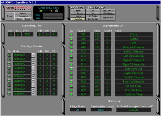
OXYGEN SENSOR HEALTH SCREEN
The O2 Health Screen (Fig. 9) shows parameters related to sensor health measurement.
Descriptions of the parameters are as follows:
EU: Displays the current voltage input from each O2 sensor.
ADC: Displays the A/D converter counts from the last sensor input measurement. Test: Displays the A/D converter counts from the last sensor test measurement. Raw: Displays the last calculated sensor health for each sensor.
Health: Displays the filtered sensor health for each sensor.
Filter: Programmable parameter sets the filter time constant for the sensor health.
With the maximum value of 1.0, there is no filtering and each sensor test becomes the new Health value. With the default filter value of 0.01, each new sensor reading becomes 1/100th of the Health value. In other words, a smaller filter value means more filtering.
Time (sec): Determines time interval (in seconds) at which sensor health test will be performed. Sensor Health test is performed every 60 seconds with the default value of 60.
Oxygen Sensor Health Screen
Figure 9
24

LEARN SCREEN
The Learn Screen (Fig. 10) displays the post-catalyst offset and valve learn tables created during the MAP programming procedure. MAP pressure and post-catalyst setpoint values are also shown on this screen. MAP programming may only be initiated from the AF900PC front panel and will be discussed later in the manual.
Each new point programmed will be entered into the proper place on the table according to the MAP pressure. The PC offset and valve pos % will change linearly between points on the table. A point may be deleted from the table by clicking into the En for that point, deleting the En with the backspace key, and entering DIS. The PC offset and valve pos % for any point may be changed by deleting the old value and entering a new value. The MAP values in the tables cannot be altered.
Learn Screen
Figure 10
25
DATA LOG SCREEN
This screen (Fig. 11) sets up the data log system and current date/time.
Data log parameters may be modified as follows:
Current Date/Time: The time and date may be changed by deleting the old value and entering a new value as required.
Data Log Schedule: Up to ten (10) daily data log times or a periodic data log interval may be used. The unit may also be set up for one (1) periodic interval time and up to nine (9) daily log times.
To enable periodic mode data logging:
1.Enter the desired data log interval.
2.Select PERIODIC mode from the drop down menu.
3.Click the EN button for that channel.
To enable daily data logging:
1.Enter the desired data log time.
2.Select DAILY mode from the drop down menu.
3.Click the En button on that channel.
NOTE: Data Log may occur as often as once per second.
Data Log Screen
Figure 11
26
Log Parameter List: The Log Parameter List (Fig. 11) shows the most important controller parameters being data logged. Disable by clicking the En buttons for any parameters you do not wish to data log. Enter “0” for the Chart # for any parameters where an excel chart is not required.
NOTE: Parameters having no numerical value (such as Status) must be assigned to chart # 0.
NAME shows the parameter name as it appears on the header on the excel spreadsheet and on the excel charts. The names may be edited if desired.
If you wish to log a parameter not shown:
1.Enter the parameter number and index.
2.Enter the parameter chart #.
3.Enter the parameter name.
The parameter number and index may be found by placing the cursor over the name of the parameter. The index is the decimal value of the parameter.
NOTE: Enter 255 for the index if the parameter does not have a decimal value.
Flash Memory: This section, shown at the bottom of Fig. 11 of the data log screen, shows the status of the Onboard Flash Memory. “# Logs Stored” indicates the number of data logs which have occurred since the last memory reset. “Capacity” shows the maximum number of data logs required to fill the memory. To “reset” memory, type “new card” in the Reset box and press enter. The flash memory will be reset when the next data log occurs. All previously recorded data on the flash memory will be lost upon reset.
27
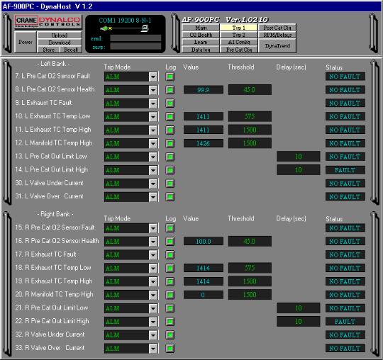
NOTE: The following descriptions apply to the Trip 1 and Trip 2 Screens
TRIP SCREEN 1
A screen (Fig. 12) used to setup the trip action for pre-catalyst system faults. The screen shows all faults set to Alarm and Data Log.
Trip Mode: Selects the action, from the drop down menu, which will be taken by the controller when the fault occurs. To make best use of the system diagnostics, it is recommended that all trips be programmed to Alarm or Shutdown so the operator will be alerted if a fault occurs. Faults that are critical to the engines health, such as high catalyst temperature, should be configured to Shutdown so the shutdown relay contacts may be used to trip the panel annunciator.
Disabled (DIS): The trip is disabled and no action will be taken.
Alarm (ALM): Trips the Alarm Relay, flashes the Alarm LED, and shows the fault on the LCD display.
Trip Screen 1
Figure 12
Shutdown (SD): Trips the shutdown relay, flashes the shutdown LED, and shows the fault on the LCD display.
Auxiliary (AUX): Trips the auxiliary alarm when fault occurs.
28
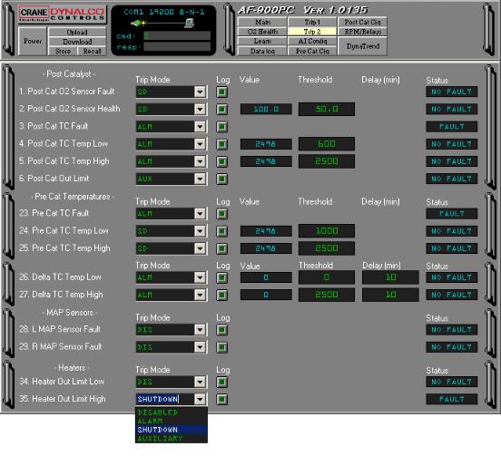
Log: Click the Log button “ON” to force a data log to internal flash memory when the fault occurs.
Value: This column displays the current value of all trips that have a numeric value.
The value displayed is after the appropriate filters have been applied.
Threshold: This column displays the trip threshold value for all trips that have a numeric value. To change a threshold value, click into the parameter and edit it.
Delay: This column indicates the delay time in seconds or minutes between the fault occurring and the trip being actuated. All delay times may be edited and have a range of 0 to 240.
Status: Indicates whether each trip is in the “Fault “ or “No Fault” condition.
TRIP SCREEN 2
This screen (Fig. 13) is used to setup the trip action for post-catalyst and catalytic converter system faults.
Trip Screen 2
Figure 13
29
 Loading...