

Page 1
5450 NW 33rd Ave, Suite 104
Fort Lauderdale, FL 33309
3211 Fruitland Ave
Los Angeles, CA 90058
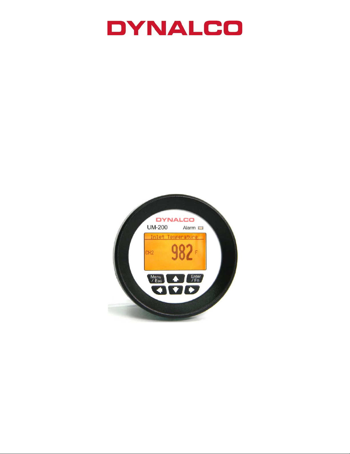
UM-200
2-Channel Monitor
Installation and Operation Manual
Rev. C
P/N145F-13019
(c) Copyright 2013, Dynalco Controls
All Rights Reserved
Published: March 28, 2013
Page 2

IMPORTANT - PLEASE READ BEFORE PROCEEDING!
The Dynalco model UM-200 is designed for reliable and rugged operation on engines,
turbines, pumps, compressors and other machinery for accurate process
measurement and protection. This product has been designed and tested to meet the
demands required in many industrial and hazardous locations meeting critical CSA
standards. The performance is directly related to the quality of the installation and
knowledge of the user in operating and maintaining the instrument. To ensure
continued operation to the design specifications, personnel should read this manual
thoroughly before proceeding with installation, operation and maintenance of this
instrument. If this product is used in a manner not specified by Dynalco, the protection
provided by it against hazards may be impaired.
WARNING
• Failure to follow proper instructions may cause any one of the following
situations to occur: Loss of life; personal injury; property damage; damage to
this instrument; and warranty invalidation.
• For clarification of instructions in this manual or assistance with your
application, contact Dynalco at (800) 368-6666 or (954) 739-4300 or send email to
customerservice@dynalco.com
•
Additional manuals and CSA certificates are available at www.dynalco.com
• Follow all warnings, cautions, and instructions marked on and supplied with the
product.
• Use only qualified personnel to install, operate, program and maintain the
product.
• Educate your personnel in the proper installation, operation, and maintenance of
the product.
• Install equipment as specified in the installation section of this manual. Follow
appropriate local and national codes. Only connect the product to power
sources and end devices specified in this manual.
• Any repair is only to be performed by Dynalco using factory documented
components. Tampering or unauthorized substitution of parts and procedures
can affect the performance and cause unsafe operation of your process.
• All equipment doors must be closed and protective covers must be in place
unless qualified personnel are performing maintenance.
•
Shutdown / alarms should be tested monthly for proper operation (see page 9)
•
Please see page 10 for CSA specific installation instructions.
1
Page 3

System Overview
The Dynalco UM-200 is capable of reading up to 2 input channels, calculating differential
value and providing an alarm / shutdown output.
Basic operation:
The UM-200 will be in “stopped” mode until a run indication is sensed. This is selectable as
either a contact closure or magnetic pickup input. Once “running” mode is sensed, the UM200 will read both inputs at a rate of 100 msec per channel. If any input crosses either an
over or under threshold, the unit will invoke a flashing red LED on the front panel as well as
an output trip (solid-state relay) that can be used for alarm or shutdown.
Additional Features
• 5 - Digit Hourmeter Function (non-resettable)
• Engine RPM Display
• Fully programmable from front keypad
• Standard SAE case size fits panels with 3-3/8 inch (86 mm) opening
Specifications
Input Types J or K type thermocouple (ungrounded) accurate to +/- 0.2 %
4 - 20 mA
0 – 1 VDC
0 - 5 VDC
0 – 10 VDC
Digital Input Clo sure to ground in dicates run condition (or use pulsed input)
Pulsed Input Magnetic pickup input for RPM display & to indicate run condition
Relay Output Digital Output rated @ 0.15 A / 48 VDC
Input Power 10 – 36 VDC
Display Backlit Graphic Display
Connections Screw Terminals
Operating Temperature Range - 40 to + 70 Deg C
Certification CSA Class I, Division 2, Groups A, B, C, D
User Interface
The UM-200 is configured via the keypad on the front panel which includes a graphical backlit
LCD display capable of displaying alpha numeric values and custom engineering units of
measure. The keypad implements a menu system, which is navigated using the up, down,
left, right, enter and escape buttons. The backlight will turn off after five minutes of inactivity
and will turn on when any of the keys are pressed.
2
Page 4
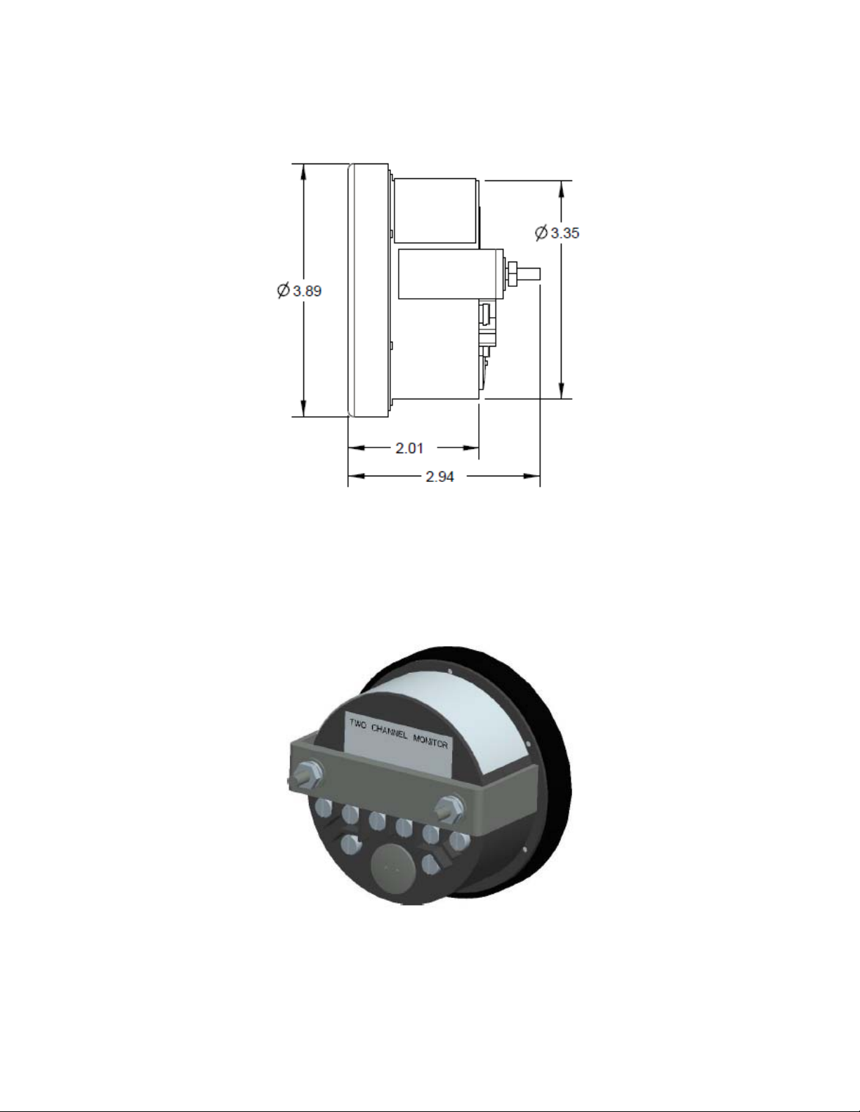
Installation
The UM-200 is designed to be panel mounted. The dimensions are shown below.
The UM-200 has a bracket for securing into the panel.
3
Page 5

Terminal Connections
All connections are made to terminals on the back of the unit.
Terminal screws to be tightened to 8 inch-pounds torque.
See page 10 for complete wiring information.
4
Page 6

Programming Overview
All programming is accomplished through the front keypad. Below is a brief description of
each key.
Press to enter or exit the configuration screens
Press to enter or accept values
Select up
Select down
Go back one screen
Select and advance to next screen
5
Page 7

Initial configuration consists of the following steps:
1) Enabling each input
2) Defining each input type
3) Defining min. & max. display values for any current or voltage inputs
4) Defining measurement display units (PSI, mV, F, C, H20, etc)
5) Setting over / under setpoint trips
6) Setting either latching or non-latching for output trip
Programming Instructions
Important: The UM-200 must first be programmed prior to operation.
When first powering up the unit, the display will first indicate the firmware version and then go
to the operational mode.
To configure each input, first go to the main programming screen by pressing the Menu /
Escape key:
The main configuration screen shows the following icons:
Run Signal – defines run status input type (if any)
Channel - enables each channel type and alarm thresholds
Calibration - defines zero & span values for DCV & mA inputs
System - allows display customization
6
Page 8

Configuration of “Run Signal”
Using the arrows on the keypad, select the “Run Signal” icon.
There are (3) run types available. The definitions are as follows:
None: No run indication required. Monitoring is always active.
RPM: Monitoring is active when signal received from magnetic pickup.
Digital: Monitoring is active when contact closure (connection to ground) is sensed.
To select run signal type, use the up / down arrows to select, then press enter.
If “None” is selected, there is no other action required other than to select “escape.” After
selecting escape, you will be asked to select “yes” to save.
If “RPM” is selected, you will need to set the # gear teeth, RPM threshold and startup delay.
The RPM threshold is the speed above which monitoring will be active. The startup delay
allows you to delay monitoring for as many as 300 seconds (5 minutes) to allow time for all
inputs to be at normal levels. If no delay is required, set to 0 seconds. The magnetic pickup
input terminals are indicated on page 3.
If “Digital” is selected, you will only need to set the startup delay (if applicable). In this mode,
a run signal will be sensed with a contact closure (or short) between the magnetic pickup
input terminals indicated on page 3.
Pressing at any time during configuration will prompt you to save the changes.
Select “Yes” to save any changes made. Selecting “No” will not save changes.
Configuration of each “Channel”
Using the arrows on the keypad, select the “Channel” icon.
Next, select the channel number to configure by pressing the up / down arrows and pressing
enter. Use the right
arrow to navigate and select the following:
Enable Channel Yes / No
Channel Type (0-1 V, 0-5 V, 0-10 V, 4-20 mA, J Type, K Type)
Description (name input with up to 20 characters)
Engineering Units (up to 3 characters for PSI, F, C etc…)
Note: For thermocouple inputs, you must enter either “F” or “C”
Enable alarms (read only or alarm?)
Alarm Type (latching or non-latching)
Alarm Output (select to enable output trip)
Alarm Low (select threshold for under-trip)
Alarm High (select threshold for over-trip)
Alarm Reset Points (select either the default reset value or manually set)
Alarm Reset Low (manually set reset hysteresis for low trip)
Alarm Reset High (manually set reset hysteresis for high trip)
7
Page 9

Differential calculations between channels 1 & 2 are also enabled by selecting the
“Channel” icon.
Configuration of “Calibration”
Using the arrows on the keypad, select the “Calibration” icon.
Next, select the channel number to configure by pressing the up / down arrows and pressing
enter.
The screens allow you to define the “Cal Zero” and “Cal Span” values for a channel that is
configured for 0-1 V, 0-5 V, 0-10 V or 4-20 mA input.
Example 1:
A pressure transmitter is connected to channel # 1. The transmitter has a 4-20 mA
output representing a pressure input of 0 - 500 PSI. The “Cal Zero” and “Cal Span”
values would be defined as:
Cal Zero = 0
Cal Span = 500
Note that the “Engineering Units” would be input as PSI in “Channel” configuration
above.
Example 2:
An oxygen sensor is connected to channel # 2. The output of the oxygen sensor is 0-1
VDC (0-1000 mV). The “Cal Zero” and “Cal Span” values would be defined as:
Cal Zero = 0
Cal Span = 1000
Note that the “Engineering Units” would be input as mV in “Channel” configuration
above.
System
Using the arrows on the keypad, select the “System” icon.
There are (2) display layouts available. Selecting layout A or B or will define the preferred
display type as follows:
Layout A: Displays both input channels plus differential
Also displays RPM & Hours if “Run Signal” configured for “RPM” input
Layout B: Displays each individual channel in large format
8
Page 10

Note that you are selecting the default layout type. You will be able to change the layout
during normal operation by pressing the left / right arrows.
Operation
Once programmed, the UM-200 will begin scanning the enabled channel inputs and will
initiate alarms based on over / under threshold values configured for each channel. It is not
necessary to define alarm threshold values for both channels as they may be for monitoring
only.
Alarm / Shutdown Output
The UM-200 will alarm when either channel value or differential value is above or below limits
as specified. Alarms can be configured as either latching or non-latching. If an alarm
condition is met, the red LED on the front panel will blink and the digital output (if enabled)
will trip. Non-latching alarms will reset the alarm if its value returns to normal. Latching alarms
require manual resetting via the front keypad.
WARNING:
Terminal connection screws to be tightened to 8 inch-pounds torque.
The alarm / shutdown output should be tested monthly for proper operation, especially
if being used for over / under pressure, over / under temperature shutdown or other
critical function.
Additional instructions for current users of Dynalco models TID-110 or STM-110 series
temperature monitors
The following products may be upgraded to the model UM-200 monitor:
TID110-11 J type thermocouple (displays in DegF)
TID110-12 J type thermocouple (displays in DegC)
TID110-13 K type thermocouple (displays in DegF)
TID110-14 K type thermocouple (displays in DegC)
STM110-11 J type thermocouple (displays in DegF)
STM110-12 J type thermocouple (displays in DegC)
STM110-13 K type thermocouple (displays in DegF)
STM110-14 K type thermocouple (displays in DegC)
Please see the programming steps in this manual for configuring the proper thermocouple
type and display in either DegF or DegC. Replacing the STM-110 series will also require
setting up the over temp alarm.
9
Page 11

10
 Loading...