

Page 1
SWTD-1000
Speed Switch / Transmitter
Operating Manual
3690 NW 53rd Street • Fort Lauderdale, FL 33309 • Ph 954-739-4300 • Fax 954-486-4968 • www.dynalco.com
Page 2

TABLE OF CONTENTS
1. Safety Instructions 1
2. Product Features 1
3. Specifications 2
3.1 General 2
3.2 Inputs 3
3.2.1 Analog Sensor Connection (Sign) 3
3.2.2 Digital Sensor Connection (IQ) 4
3.2.3 Sensor Supply 4
3.2.4 Binary Input 5
3.3 Outputs 5
3.3.1 Analog Output 5
3.3.2 Relay 6
3.3.3 Open Collector Output 6
3.4 Data Communication 6
3.4.1 Serial Interface (RS 232) 6
3.5 Environment 6
3.5.1 Climatic Conditions 6
4. Principle of Operation 7
4.1 General 7
4.2 Machine Factor 8
4.2.1 Displaying other Physical Values 8
5. Installation 9
6. Connections 9
6.1 Front View 9
6.2 Terminals 10
7. Hardware Configuration 11
7.1 Analog Sensor Input (Sign) 11
7.2 Digital Sensor Input (IQ) 11
8. Configuration with PC Software 12
8.1 Software Concept 12
8.2 PC Communications 12
8.3 PC Software Settings 12
8.3.1 Interface (Settings Æ Interface) 12
8.3.2 Display Interval (Settings Æ Display Interval) 12
8.4 Param eter List and Ranges 13
8.5 Parameters 14
8.5.1 System Parameters (Configuration Æ System) 14
8.5.2 Sensor Parameter (Configuration Æ Sensor) 14
8.5.3 Analog Output (Configuration Æ Analog Output) 15
8.5.4 Limit (Configuration Æ Limit) 15
8.5.5 Relay parameter and selection of Parameter set 16
9. Operating behavior 17
9.1 Power on 17
9.1.1 Analog Output 17
9.1.2 Relay Output 17
9.2 Measurement 17
9.2.1 The adaptive Trigger Level 17
9.2.2 Signal Failure 18
9.3 Functions 18
9.3.1 Limits and Window Function 18
9.3.2 Parameter Set A and B 18
9.3.3 Relay Hold function 18
9.3.4 Push-Button 18
9.3.5 Binary Input 19
9.4 Fault Behavior 19
9.4.1 Sensor Fault (Sensor Monitoring) 19
9.4.2 System alarm 19
9.4.3 Alarm 19
9.5 Power supply interruption 19
10. Mechanical Construction / Housing 20
11. Accessories 20
Page 3

Operating Instructions SWTD-1000 DYNALCO
1. Safety Instructions
SWTD-1000 may only be connected by trained & compete nt per so n ne l.
Before opening the SWTD-1000 (Hardware configuration) the unit must be disconnected
from circuits that may exhibit dangerous potentials.
The instructions in this operating guide m ust be strictly adhered to. Not doin g so may cause harm to
personnel, equipment or plant.
Instruments in a doubtful condition after electrical, climatic or mechanical overload must be immediately
disconnected and returned to the manufacturer for repair.
2. Product Features
The SWTD-1000 measures and monitor fr equencies (speed proportional values) in the range
0 to 35,000 Hz.
The following are available:
• 1 Current output
• 1 Sensor frequency output
• 1 Relay
• 2 Limits
• 2 Parameter sets – selectable via binary input
• Sensor monitoring
• System monitoring
This product is configured via SWTD-1000 PC configuration software.
All settings are in revolutions per minute (RPM).
1//
Page 4
Operating Instructions SWTD-1000 DYNALCO
3. Specifications
3.1 General
SWTD-1000
Lowest measuring range 0 . . . 1.000 Hz
Highest measuring range 0 . . . 35.00 kHz
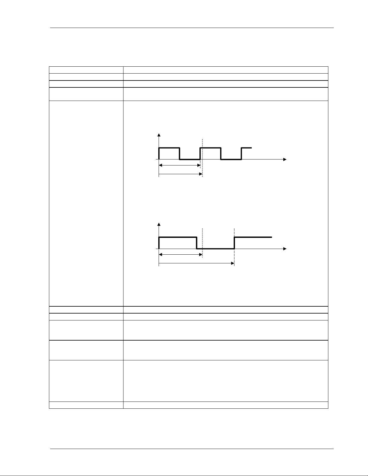
Minimum Measuring time
(Fixtime)
Effective Measuring time Is based on the minimum measuring time (Fixtime) an d the measured
Selectable values: 2 / 5 / 10 / 20 / 50 / 10 0 / 200 / 500ms
1 / 2 / 5 Seconds.
frequency.
• Input frequency period < Fixtime
End of Fixtime
Input
frequency
Input period
Fixtime
typically: t
max: t
= Fixtime
effective
= 2 x Fixtime
max
• Input frequency period > Fixtime
End of Fixtime Ensuing edge
Input
frequency
Fixtime time
Period of input signal
max: t
max
= 2 x input frequency period
• In the event of sensor signal failure:
t
= Fixtime + (2 x last input fre quency period)
effective
Resolution 0.05 %
Power supply range 10...36 VDC
Power consumption 10 V : 2.3 W
24 V : 2.6 W
36 V : 3.0 W
PSU failure bridging 16 V : 4 ms
24 V : 25 ms
36 V : 75 ms
Isolation Galvanic isolation between:
• Power supply,
• Sensor input incl. sensor supply, Binary input, Serial interface
• Analog output
• Relay output
• Open collector output
Isolation voltage 700 VDC / 500VAC
time
2//
Page 5
Operating Instructions SWTD-1000 DYNALCO
3.2 Inputs
3.2.1 Analog Sensor connection (Sign)
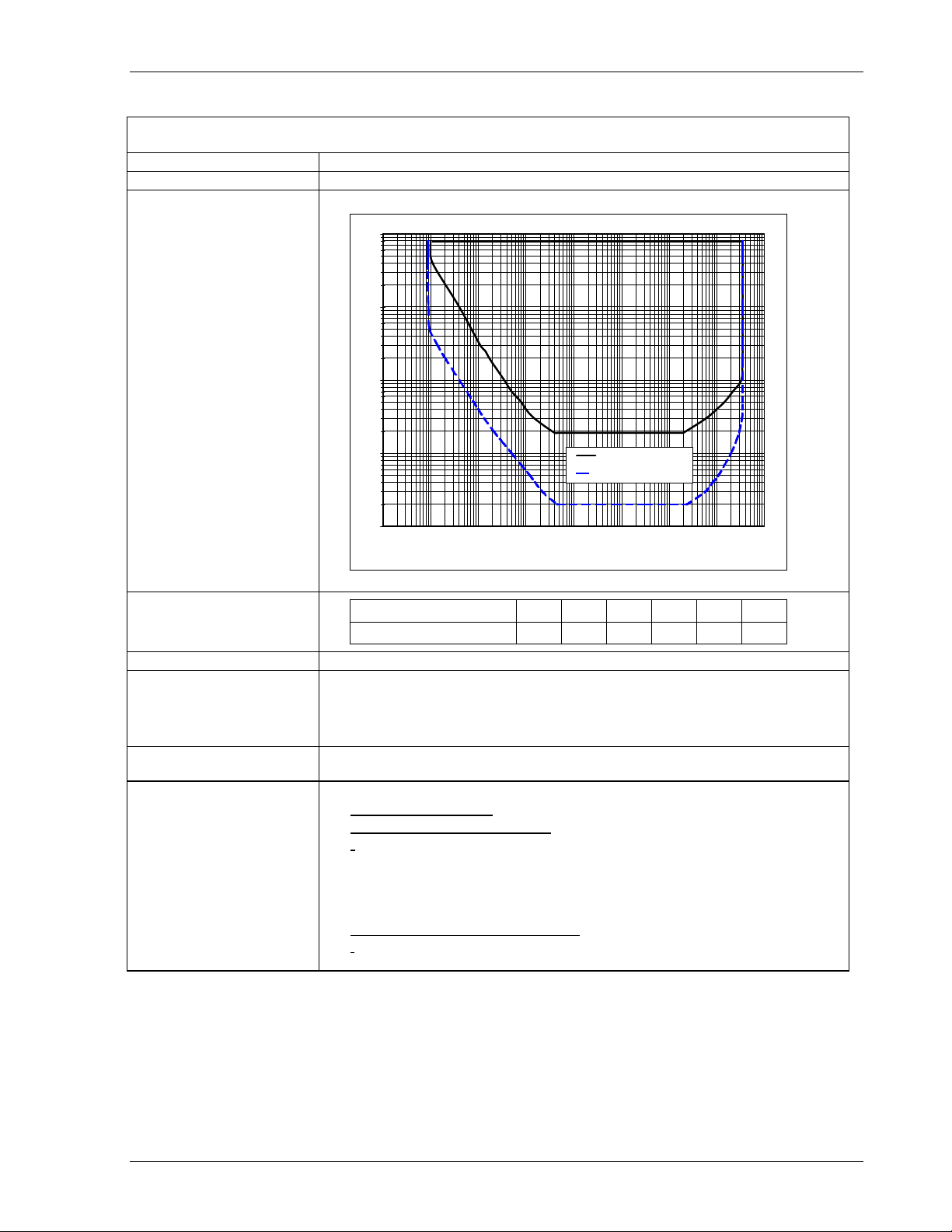
Frequency range (-3dB) 0.01 Hz / 35 kHz
Input impedance 30 K
Input voltage
• Max. 80V
•
100
10
1
Input voltage [Veff]
rms
Max. frequency against input voltage
O.K.
0.001
NOT O.K.
0.01
Trigger: 500mVpp
Trigger: 20mVeff
0.1
1
10
Frequency [Hz]
100
1000
10000
100000
Minimum positive pulse
width - digital signals Input
voltage
0.1
0.01
Signal voltage [Vpp] 0.5 1 2.5 5 10 20
Min. pulse width [µs] 2000 667 333 200 166 125
Integrated pull-up 820 Ohm to +V of the sensor supply (with Ju mp er J1)
Trigger level adaptive Trigger level.
Configurable with Jumper J2:
• 250mV … 6.5V (>500mVpp) [Factory configuration ]
• 28mV … 6.5V (>20mV
rms
)
Screen A terminal is provided for the sensor cable screen. This terminal is connected to
the sensor supply 0V. (0VS)
Sensor monitoring 1 of 3 settings may be configured via software:
• No Sensor Monitoring
• Monitoring of powered sensors
Also for 2 wire sensors supplied via the Pull-up resistor (Jumper J1) ].
[
Æ The sensor is considered to be defective if the sensor current
consumption falls outside of I
= 0.5…25 mA
I
min.
I
= 0.5…25 mA
max.
min
and I
• Monitoring of non powered se nsors
For 2 wire sensors such as electromagnetic sensors.]
[
.
max
Æ The sensor is considered to be defe ctive if the circuit is disconnected.
3//
Page 6

Operating Instructions SWTD-1000 DYNALCO
3.2.2 Digital Sensor Connection (IQ)
Frequency range (-3dB) 0.01 Hz / 35 kHz
Input impedance 46 K
Input voltage Max. ± 36V peek
Minimum pulse width Min. pulse width 1.5 µs
Trigger level
• min.U
• max.U
= 1.6 V
low
high
= 4.5 V
Screen A terminal is provided for the sensor cable screen. This terminal is connected to
the sensor supply 0V. (0VS)
Sensor monitoring 1 of 2 settings may be configured via software:
• No Sensor Monitoring
• Monitoring of powered sensors
[
Also for 2 wire sensors supplied via the Pull-up resistor (Jumper J1) ].
Æ The sensor is considered to be defective if the sensor current
consumption falls outside of I
= 0.5…25mA
I
min.
I
= 0.5…25mA
max.
min
and I
max
.
3.2.3 Sensor Supply
SWTD-1000
+14 V , short circuit proof
+5V , short circuit proof
SWTD-1000 SWTD-1000
Current
[mA]
Voltage
[V]
Voltage
[V]
0 14.29 5.50
1 14.23 5.41
5 14.13 5.30
10 14.04 5.21
15 13.95 5.10
20 13.86 5.03
25 13.79 4.94
30 11.85 4.86
35 10.45 4.78
40 9.32 4.69
45 8.35 4.59
50 7.58 4.20
55 6.98 3.90
60 6.48 3.62
If the current limit activates, the sensor supply must be disconnected to reset
the protection.
4//
Page 7
Operating Instructions SWTD-1000 DYNALCO
3.2.4 Binary Input
Use For external selection of Parameter set A or B.
• Logic 1 = Parameter set A (Relay control A)
• Logic 0 = Parameter set B (Relay control B)
Levels Logic 1 = V > +3.5V
Logic 0 = V < +1.5V
Reference Sensor supply 0V
Max voltage 36V
Input resistance
R
min
= 10KΩ
Circuit Internal pull up resistance to 5V
Shorting the binary input to the sensor 0V
parameter set A B
+Bin
pushbutton
5 volts
SWTD-1000
analysis
creates logic 0.
OVS
3.3 Outputs
3.3.1 Analog Output
Type Current
Load Max. 500 Ohm
Open circuit voltage Max. 12V
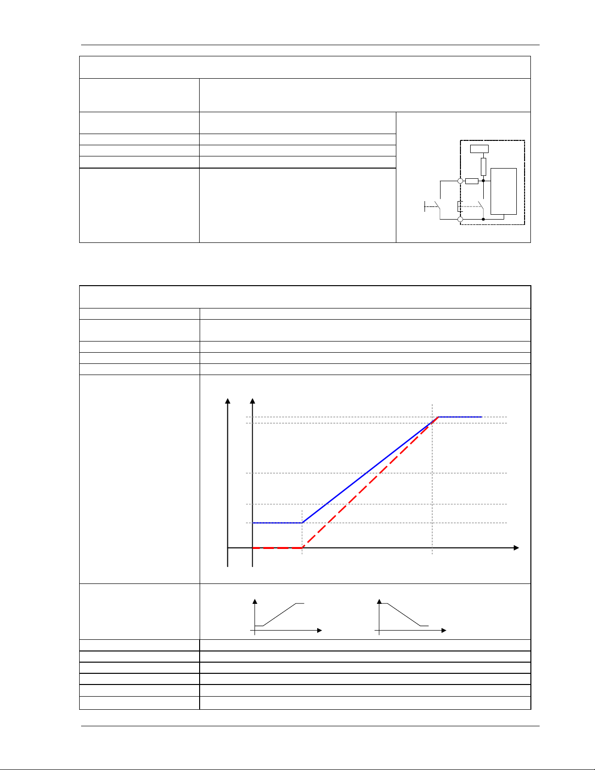
Operating mode
SWTD-1000
0…20 / 4…20 mA
[mA]
21
20
4...20mA mode
12
4
0...20mA mode
0
initial value final value
Transfer functions Normal or Inverse (rising or falling characteristic)
output
„normal“
speed
output
„invers“
Resolution 12 Bit (4096 steps)
Max Linear error 0.1 %
Accuracy 0.5 % of the full range value.
Damping Hardware 11 ms + Software setting (Configuration)
Temperature Drift
Typically ± 100 ppm/K, max. ± 300 ppm/K
Reaction time Effective measuring time + 7.5ms
(minimal measured
speed
value)
speed
[rpm]
5//
Page 8

Operating Instructions SWTD-1000 DYNALCO
3.3.2 Relay
Type Single Pole Double Throw
Limit Hysteresis Programmable – 1 lower and 1 upper set point per limit.
Functions 2 programmable parameter sets selectable via binary input
• Reaction to Alarm, Sensor fault, Limit, always on or off.
• “Normal“ or ”Inverse“ (normally de-enerized or energized)
• With or without ‘Hold function’ (Reset via Binary input)
Accuracy 0.05% of the valu e se t
Temperature tolerance
Reaction time Effective measurement time + 10.5ms
Contact rating AC: max. 250VAC, 1250VA.
Contact isolation 1500 VAC
Max. ± 10 ppm of the value set
DC:
3.3.3 Open Collector Output
Type Opto-coupler (passive)
External Pull-up R = 91 x V (Ic nominal = 11 mA)
Load voltage V = 5 – 30 V
Max load current 25 mA
Isolation 1500 VAC
3.4 Data Communication
3.4.1 Serial Interface (RS 232)
Physical Layer Similar to EIA RS 232 but with +5V CMOS Level
Max cable length 2 m
Transmission rate 2400 Baud
Connection Front panel, 3.5mm jack plug
3.5 Environment
3.5.1 Climatic Conditions
Operating temperature - 20 ... + 70 °C
Storage temperature - 20 ... + 70 °C
Relative humidity 75% averaged over the year; up to 90% for max 30 days.
Condensation to be avoided.
6//
Page 9

Operating Instructions SWTD-1000 DYNALCO
X
4. Principle of Operation
4.1 General
The SWTD-1000 is controlled by a microprocessor. It works according to the period measurement
principle whereby the input period is measured with subsequent computing of the reciprocal value
corresponding to the frequency or speed. The relationship between frequency and speed is established
with the Machine factor.
The current output and relay control are determined from the speed.
The relay function is defined via 2 selectable parameter sets. Each parameter set can access the 2 limit
values, the alarm definition, sensor monitoring and other process values.
The 2 limits each have and upper and lower set point (hysteresis setting)
The selection of the valid parameter set is via the binary input.
The relay status may be held un til reset via the binary input
The system continuously monitors itself. In addition the sensor may be monitored. Dep endent upon the
configuration, these conditions can influence the relay and current output.
The alarm status is indicated via the front panel LED.
The frequency output (open collector output) is not influenced by the machine factor and corresponds to
the input signal frequency.
The input of all parameters is via PC software and the RS232 interface. This may also be used to
interrogate the unit’s settings, measurement and general status.
Parameters are retained in an EEPROM.
binary
input
Analysis of the
binary input
Reset
Choice of the parameter set A/B
Sensor
connection
Sensor supply
Sensor control
Periodic time
measurement
EEPROM
RS 232
Frequency
calculation
Sensor failure
Frequency
System control
Machine
factor
System failure
Speed
Display
Definition Alarm
Definition limit 1
Definition limit 2
Definition current output
Definition
Relay
LED
Relay
Current
output
Open
Collector
7//
Page 10

Operating Instructions SWTD-1000 DYNALCO
4.2 Machine Factor
The machine factor establishes the relationship between sensor frequency (Hz) and corresponding speed
(RPM).
Machine Factor = Frequency
RPM
If the # gear teeth and RPM are known, use the following formula to calculate corresponding frequency:
Signal Frequency (Hz) = (RPM) X (Teeth or Discontinuities)
60
Another way to calculate the machine factor is:
Machine Factor = (Teeth or Discontinuities)
60
Note: The above formulas are based on the gear or target turning at the same speed as the machine being
monitored, ie: no step up or step down gear ratios involved.
4.2.1 Displaying Oother Physical Values
In principle any physical value that can be measured proportional to speed may be dis played.
The formulae above should then be modified accordingly.
8//
Page 11

Operating Instructions SWTD-1000 DYNALCO
5. Installation
The SWTD-1000 may only be installed by trained and competent personnel. An undamaged SWTD-1000,
valid configuration and suitable installation are required. Please note the Safety Instructions in Section 1.
The power to the SWTD-1000 should be capable of being disconnected via a switch or other emergency
means.
Before switching the equipment on the power supply voltage should be verified to be in the permissib le
range.
The sensor cable screen must be connected to the terminal ‘Sh’ so as to minimize the influence of noise.
This terminal is directly connected internally to 0VS.
6. Connnections
6.1 Front View
The SWTD-1000 display along with the RS23 2 interface and the status LED are located a t the front.
Communications via RS232 are described in section 8.2.
9//
Page 12

Operating Instructions SWTD-1000 DYNALCO
6.2 Terminals
SWTD-1000
Sh 0VS Ana.
Sensor connections
SH : Screen – Sensor cable
0VS : Sensor Reference voltage
+VOut : Sensor Supply
Ana. : Sensor signal analog
Dig. : Sensor signal digital
Open Collector output
+PO : Open Collector Output
-PO : Signal reference for the Open
Collector
Relay output
NC : Normally closed
NO : Normally open
Com : Common
+Vout
Dig. +Bin +PO -PO NC NO Com +AO -AO
Analog output
+AO : current positive
- AO : current negative
Supply
+24V : Power (10 ... 36 V)
Gnd : Power reference
: Earth
Gnd +24V
10//
Page 13

Operating Instructions SWTD-1000 DYNALCO
7. Hardware Configuration
7.1 Analog Sensor Input (Sign)
Jumper position J1: Sensor type J2: Adaptive trigger level range
2 wire sensors
(with 820Ohm Pull Up resistance)
J1
J2
28mV to 6.5V (>20mV
rms
)
3 wire and electromagnetic sensors
(factory setting)
250mV to 6.5V (>500mVpp)
[factory setting]
7.2 Digital Sensor Input (IQ)
No hardware configuration po ssible or necessary.
11//
Page 14

Operating Instructions SWTD-1000 DYNALCO
8. Configuration with PC Software
8.1 Software Concept
All settings are written via PC to the SWTD-1000 using the RS232 interface an d the aid of the user friendly
menu driven SWTD-1000 software.
The parameter file may be stored, opened, printed and exchanged between the SWTD-1000 and a PC.
8.2 PC Communications
Communications with the SWTD-1000 are initiated by the PC via the RS232 interface.
Prior to starting comms, Settings Æ Interface must be set to an appropriate serial interface.
The following settings also apply:
Transmission rate: 2400 Baud
Parity Bit: none
Data Bits: 8
Stop Bits: 2
Connector: 3.5mm jack plug
5 1
female
2
3
5
TXD
RXD
GND
TXD RXDGND
9
6
The diagram shows the stereo jack plug to D9 connections.
The tachometer RXD must be connected to the PC’s TXD and vice versa.
The SWTD-1000 does not use a standard RS232 signal (-5V…+5V) but operates at 5V CMOS levels,
compatible with most PC’s as long as the cable is not longer than 2m.
A suitable cable may be ordered from DYNALCO – see section 11.
8.3 PC Software Settings
8.3.1 Interface (Settings Æ Interface)
In this menu the serial interface for communication with the SWTD-1000 is defined.
8.3.2 Display Interval (Settings Æ Display Interval)
The SWTD-1000 measurement status may be interrogated and display ed on the PC via SWTD-1000 Æ
Start – Reading Measure Data.
The display update time may be set at intervals of ¼ to 10 seconds.
12//
Page 15

Operating Instructions SWTD-1000 DYNALCO
8.4 Parameter List and Ranges
If you already have a configuration file you can open and view it using the SWTD-1000 Windows
Software menu
File Æ Open
You can also connect the SWTD-1000 to a PC (see section 8.2) and read back the parameters,
SWTD-1000 Æ Read parameters
Once loaded into the software the parameter set may be printed via File Æ Print
Normal Windows file handling rules apply.
Parameter list and ranges. Factory settings are shown in bold.
Configuration < System >
Machine factor 1.0000E-07 ... 1.0000 ... 9.9999E+07
Minimum Measuring time
Min displayed measured value
Alarm definition
Configuration < Sensor >
Sensor Type Active / Passive
Sensor input
Sensor current minimum
Sensor current maximum
Configuration < Analog output >
Measuring range start value
Measuring range end value
Output range 0 ... 20mA / 4 ... 20mA
Time constant (Damping)
Configuration < Limits >
Status Limit 1
Status Limit 2
Mode Limit 1
Mode Limit 2 Normal / Inverse
Lower Set point Limit 1
Upper Set point Limit 1
Lower Set point Limit 2
Upper Set point Limit 2
Configuration < Relay control >
Switching of control A/B
Selection of actuator
Delay time
Relay Assignment
Control A
Acknowledge A
Acknowldge B
Acknowldge B
2 / 5 / 10 / 20 / 50/ 100 / 200 / 500 ms / 1/ 2 / 5 Seconds
1.0000E-12 ... 1 ... 1.0000E+12
Only System error System error OR Sensor Monitoring
Analog (Sign) / Digital (IQ)
0.5 ... 1.5 ... 25.0mA
0.5 ... 25.0mA
0.0000 ... 90% of the end value
1Hz … 2000.0 … 500000
0.0 ... 9.9s
On / Off
On / Off
Normal / Inverse
0.1 … 200.00 … 500000
0.1 … 300.00 … 500000
0.1 … 400.00 … 500000
0.1 … 500.00 … 500000
None (always control A) / Binary Input B1
0 ... 2.000 s
Alarm / Sensor monitor / Limit 1 / Limit 2 / Window / On / Off
Without acknowledge (no hold function) /
Relay held when control active /
Relay held when control inactive
Alarm / Sensor monitor / Limit 1 / Limit 2 / Window / On / Off
Without acknowledge (no hold function) /
Relay held when control active /
Relay held when control inactive
13//
Page 16

Operating Instructions SWTD-1000 DYNALCO
8.5 Parameters
Parameters are changed in the sub menus from the drop down menu “Configuration“.
Warning:
New configurations only become ac tive after being downloaded into the SWTD-1000 via:
SWTD-1000 Æ Write Parameters
8.5.1 System Parameters (Configuration Æ System)
Machine Factor
The machine factor establishes the relationship between sensor frequency and assoc iated speed.
Machine Factor = Frequency
RPM
See section
4.2 Machine Factor.
Once the correct machine factor is entered, all other settings e.g limits are made in RPM.
Minimum Measuring Time
The minimum measuring time determines the time during which the input frequency is measured. Once
this time has lapsed, the calculation is made following the end of the running signal period. The
minimum measuring time may be increased to filter ou t fr equency jitter so as to display a stable reading
but at the cost of increased reaction time.
Minimum Displayed Value
The minimum displayed value is a measured value under which “ 000 0” is displayed.
Alarm Definition
This function defines the alarm. It may be only system error or a logical OR combination of system error
OR sensor monitoring. During an al arm the LED is off. In addition, the relay is deactivated and the
analog output goes to 0mA irrespective of the output range.
8.5.2 Sensor Parameter (Configuration Æ Sensor)
Sensor Type
The type of sensor to be used is defined here.
<Sensor active>
the internal pull up resistor. (Jumper J1).
<Sensor passive>
See also section 0 9.4.1 Sensor Fault (Sensor Moni to ring ) .
Sensor Iinput
The sensor input “analog” (Sign) or “digital” (IQ) is defined here.
Sensor Current Minimum
As long as the sensor current consumption lies above the value <Current Minimum>, the sensor is
considered to be functioning correctly.
Sensor Current Maximum
As long as the sensor current consumption lies below the value <Current Maximum>, the sensor is
considered to be functioning correctly.
14//
is for monitoring sensors powered by SWTD-100 0 including 2 wire sensors supplied via
is for monitoring non powered sensors e.g. 2 wire VR (passive) sensors.
Page 17

Operating Instructions SWTD-1000 DYNALCO
8.5.3 Analog Output (Configuration Æ Analog Output)
[mA]
21
20
4...20mA mode
12
(minimal measured
value)
4
0...20mA mode
0
initial value final value
Measuring range – start value
Analog output start value 0 or 4mA
Measuring range – end value
Analog output end value 20mA
In the case of a negative tr ansfer function the end value must be set smaller than the start value.
Output range
0…20mA or 4…20mA
Output time constant
The analog output signal may be smoothed by applying a software time constant. This damping is
deactivated when the time constant is 0.0 seconds.
speed
[RPM]
8.5.4 Limit (Configuration Æ Limit)
The SWTD-1000 series offers 2 independent limits Æ Limit 1 and 2.
Status
Limits are selected her e. If the limit is deac tivated, the other values such as set points and m ode have
no further effect.
Mode
In Normal Mode the limit is active as soon as the High set point is exceeded. In Inverse Mode the limit is
active from the start (zero speed) and deactivates when the set point is reached (Fail Safe operation)
Upper and Lower Set point
lower
limit
activated
deactivated
switching point
As the speed increases, the limit switches when the High set point is reached and remains in that
condition until the spe ed reduces past the Low set point.
15//
upper
switching point
rpm
Page 18

Operating Instructions SWTD-1000 DYNALCO
8.5.5 Relay Parameter and Selection of Parameter Set
(Configuration Æ Relay control)
Parameter set A / B selection
As standard parameter set B may be activated via the binary input <Binary input B1>.
If parameter set B is to be deactivated, this setting should be none (always control A)
Delay time when switching A <- B
This value determines the delay from switching the binary input to the switc hing from parameter set B to
parameter set A.
Relay assignment with control A
Defines the relay behavior in parameter set A.
Relay assignment with control B
Defines the relay behavior in parameter set B.
Relay
Status register Relay dependency
• Alarm
• Sensormonitor
• Limit 1/2
• Window
• On
• Off
Defines the source information for relay switching.
(Common) Alarm (8.5.1 System Parameters (Configuration Æ System))
Sensor status (8.5.2 Sensor Parameter (Configuration Æ Sensor))
Selection of Limit 1/2 (8.5.4 Limit (Configuration Æ Limit))
ExOR combination of both limits
The relay is on
The relay is always off
Acknowledge
Acknowledge establishes if and un der what conditions the relay status is held. A relay that is held no
longer reacts to the assigned signal and can only be reset via the binary input.
16//
Page 19

Operating Instructions SWTD-1000 DYNALCO
9. Operating Behavior
9.1 Power On
9.1.1 Analog Output
Following power on the output assumes the output range start value. Upon completion of the first
measurement the output goes to the corresponding measured value.
9.1.2 Relay Output
The parameter set determined by the configuration and binary input is valid from the start.
If the relay is assigned to a limit it remains deactivated until com pletion of the first measuremen t,
following which it assumes the stat us defined under Limit.
If the relay is assigned to any other item in the status register it immediately assumes the corresponding
status.
If no input frequency is present then after a period of 2 x Fixtime a measured value below the lower set
point is assumed.
9.2 Measurement
Every measurement begins wit h the positive edge of the input s ignal. Once the Fixtime has lapsed the
next positive edge ends the running me asu re m e n t an d star ts the next.
The resulting effective measurement time is dependent upon whether the input signal period is longer or
shorter than the Fixtime.
Input signal period < Fixtime Input signal period > Fixtime
End of Fixtime Ensuing edge
Input
Frequency
Input period time
Fixtime
Effective measurement period
t
Messung typisch
t
Messung maximal
= Fixtime
= 2 x Fixtime
The total measurement time has a resolution of ± 0.4 μs.
The calculation and adaptation of outputs follows immediately after the Fixtime.
With input frequencies outs ide of the measuring range, the corresponding final values are assumed.
9.2.1 The Adaptive Trigger Level
After triggering, the trigger level is set for the
next pulse anew.
This guarantees that the trigger level can follow
a 50% reduction in speed from pulse to pulse.
DC offset, resonance and negative pulses have
no influence on the triggering
Input
Frequency
t
Messung maximal
End of Fixtime Ensuing edge
Fixtime time
Period of input signal
Effective measurement period
Fixtime
= 2 x Input signal period
U
old trigger level
trigger level
signal to
noise ration
bad sensor
signal
t
17//
Page 20

Operating Instructions SWTD-1000 DYNALCO
9.2.2 Signal Failure
In the event of a sudden loss of a good signal no positive edge arrives to complete the measurement or
start a new one. Once the minimum measurement time (Fixtime) has lapsed the unit waits for twice the
last measurement period followin g which half the last measured speed is ass umed. If the signal remains
missing then the measurement approaches zero following an e-function.
9.3 Functions
9.3.1 Limits and Window Function
Since the upper and lower sets points are freely selectable a large hysteresis may be set. If that is not
necessary we recommend setting a 10% hysteresis.
The Window function allows an Exclus ive OR combination of Limits 1 and 2, whereby the status of both
limits is first determined (including any inversion) and a subsequent ExOR comparison executed.
As soon as Relay assignment is <Window> the relay behaves as follows:
• With identical limit modes (both Normal or both Inverse) the relay is activated when the measured
value lies between the Limit 1 and 2 settings.
• If different modes are set (one Normal and the other Inv erse) the relay is deactivat ed when the
measured value is between Limts 1 and 2.
9.3.2 Parameter set A and B
The SWTD-1000 has 2 parameter sets available that define the relay assignment. Parameter set A
would normally be used. If another parameter set is needed, e.g. for test purposes, the binary input may
be used to change to parameter set B. The transfer from parameter set B to parameter set A may be
delayed in the range 0 to 2000 seconds. Transferring from A to B is however immedi ate and not affected
by this setting.
To be able to select parameter sets us ing the binary input, Relay control - Selection of Actuator must be
appropriately set, see 0.
Binary Input Condition Selected Parameter Set
High (5V) “normal“ A
Low (0V) “connected to 0V“ B
9.3.3 Relay hold function
A latch function may be assigned to the relay. By selecting <Relay is hold if control is active> the relay is
activated once the assigned limit is active and remains held even if the input frequency would no longer
cause a trip. By selecting <Relay is h old if control is inactive>, th e deactivared state of the relay is held.
The latched status may be reset by cycling power or via the binary input, whereby the binary input must
be activated as per the configuration (0V or 5V) for between 0.1 and 0.3 seconds.
9.3.4 Push-Button
The front panel push button internally connects the binary input to 0VS th us generating a logic 0.
18//
Page 21

Operating Instructions SWTD-1000 DYNALCO
9.3.5 Binary Input
2 functions are executable using the binary inpu t:
• Switching between parameter sets A and B. See 0 9.3.2 Parameter set A and B.
• Resetting a latched relay. See 9.3.3 Relay.
The binary input has an internal pull up resistor to +5V and is
therefore normally logic High .
5 Volt
Shorting the binary input to the sensor supply 0V creates a logic
0.
Switching the input for between 0.1 and 0.3 seonds resets a
parameter set A B
+Bin
pushbutton
10k
analysis
latched relay but does not influence parameter set selection,
which requires longer than 0.3 seconds.
OVS
9.4 Fault Behavior
9.4.1 Sensor Fault (Sensor Monitoring)
The sensor may be monitored in 2 ways. With sensor s powered by the SWTD-1000 the sensor
supply current is monitored. If the current falls outside the permitted range then sensor fault is
indicated. If the sensor is not powered by the SWTD-1000 then it may only be monitored for
disconnection. If disconnected, sen sor faul y is indicat e d.
The SWTD-1000 behavior in the event of a senso r fault is dependent on the configuration:
Alarm Configuration
LED
Only System error
System error OR Sensor monitoring
Outputs in the event of a sensor fault
Analog output
Current
Relay
On Measured value output per configuration
Off 0mA 0V deactivated
9.4.2 System Alarm
If the microprocessor detects a checksum fault (RAM, ROM or EEPROM) the measured value is set to
0rpm, the analog output goes to 0/4mA and the relay is deactivated.
Alarm Configuration
Outputs in the event of a System alarm
LED
Analog output
Current
Only System error
System error OR Sensor monitoring
Off 0mA 0V deactivated
9.4.3 Alarm
As long as a combined alarm is pres ent no measurements are conducted and the outputs behave as
described above. Once the fault or alarm condition is removed the last correct measured value is
assumed. Eventual limit activation is not taken into account.
9.5 Power Supply Interruption
If the PSU remains off for longer than the permitted period the outputs deactivate i.e. the analog output
goes to 0mA, the relay deactivates and the “open collector“ ouput be comes high resistance.
Once the supply resumes in range the SWTD-1000 begins its initialization routine.
Relay
19//
Page 22

Operating Instructions SWTD-1000 DYNALCO
10. Mechanical Construction / Housing
Mounting Using DIN 43835 Form B clamps
Terminals Detachable Terminal block.
2.5 mm 2 - Cable or 1.5 mm2 flex
AWG 24 – AWG 12
UL CSA
Sealing to EN 60925
resp. IEC 925
Dimensions
Housing IP 40
Terminals IP 20
11. Accessories
Interface cable PC – SWTD-1000, Part No. PC-T400
20//
 Loading...