

Page 1

SWT-2000
Frequency Measurement and
Switching Instrument
Operating Manual
3690 NW 53
rd
Street • Fort Lauderdale, FL 33309 • Ph 954-739-4300 • Fax 954-486-4968 • www.dynalco.com
Page 2

TABLE OF CONTENTS
1. Product Features 1
2. Specifications 2
2.1 General 2
2.2 Inputs 2
2.2.1 Sensor Inputs 2
2.3 Binary Inputs 5
2.4 Outputs 5
2.4.1 Analog Outputs 5
2.4.2 Relays Outputs 6
2.4.3 Open Collector Outputs 7
2.5 Data Communication 7
2.5.1 Ethernet 7
2.6 Environment 7
2.6.1 Climatic Conditions 7
2.6.2 Electromagnetic Immunity 7
3. Principle of Operation 8
3.1 General 8
3.2 Machine Factor 8
4. Installation 9
5. Connections 9
5.1 Front View 9
5.1.1 Front View 9
5.1.2 Terminal A 10
5.1.3 Terminal B 11
6. Configuration via PC Software 12
6.1 Software Concept 12
6.2 PC Settings 12
6.3 Download Configuration Software 12
6.4 Configuration Software 13
6.4.2 Log in 13
6.4.3 Main Window and System Limit Matrix 13
6.4.4 Logging In and Out 13
6.5 Configuration File 13
6.5.1 ... creating new 13
6.5.2 ... resetting to factory default 14
6.5.3 ... loading 14
6.5.4 ... saving 14
6.5.5 ... printout 14
6.6 Communication with the SWT-2000 14
6.6.1 Read Measured Data 14
6.6.2 Reading Configuration from the SWT-2000 14
6.6.3 Writing a Configuration to the SWT-2000 15
6.6.4 Compare Data 15
6.7 Configuring 15
6.7.1 Speed Sensors 15
6.7.2 Binary Input Configuration 16
6.7.3 Set Measurement Interval 16
6.7.4 Sensor Alarm 16
6.7.5 Machine Factor 17
6.7.6 Dynamic Error 17
6.7.7 Math Function 18
6.7.8 System Limit 19
6.7.9 Relay Outputs 20
6.7.10 Open Collector Outputs 20
6.7.11 Analog Output 21
6.7.12 Copy Parameter Set 22
6.7.13 Change-Over Delay 22
6.8 Settings 22
6.8.1 Ethernet Interface 22
6.8.2 Changing the Password 23
6.9 Info 23
7. Behavior 24
7.1 Power On 24
7.1.1 Analog Output 24
7.1.2 Relay Output 24
7.1.3 Open Collector Output 24
7.2 Frequency Measurement 25
7.2.1 The Adaptive Trigger Level 25
Page 3

7.2.2 Signal Failure 26
7.3 Functions 26
7.3.1 "FUNC" Push Button 26
7.3.2 Parameter Sets A, B, C and D 26
7.3.3 Limits 26
7.3.4 Math Function 27
7.3.5 Frequency X2 and X4 28
7.3.6 Relay and Open Collector Latch Function 28
7.3.7 Analog Output 28
7.3.8 Interpretation of System Limit Inputs 29
7.4 Fault Behavior 29
7.4.1 Sensor Error 29
7.4.2 System Alarm 29
7.5 Power Failure 29
7.6 Behavior During Configuration 29
8. Mechanical Construction / Housing 30
8.2 Mounting 30
9. Accessories 31
Copyright © 2009 Dynalco. All rights reserved.
Part Number: SWT-2000
SWT-2000 Rev. 1, June 2009
Page 4

Page 5

Operating Instructions SWT-2000 DYNALCO
1. Product Features
The model SWT-2000 measures and monitors frequency signals (speed proportional values) in the
range 0.025Hz to 50,000Hz.
Available are:
• 2 Frequency Inputs (Speed sensors)
• 2 Analog outputs
• 2 Binary input
• 4 Relays
• 2 Open Collector Outputs
• 4 Parameter sets each having 6 System limits with 4 Limit values
• Sensor monitoring
• System monitoring
The SWT-2000 is configured via Computer (PC) using resident operating software.
2 models are available:
SWT-2000: 2 channel Speed Switch / Transmitter with 4 Relays and 2 Analog outputs 0/4-20mA
SWT-2000AC: (AC Version)
SWT-2000DC: (DC Version)
1
Page 6

Operating Instructions SWT-2000 DYNALCO
2. Specifications
2.1 General
Measurement time 2ms / 5ms / 10ms / 20ms / 50ms / 100ms / 200ms / 500ms / 1s / 2s / 5s
(Frequency measurements might take longer than the predefined measurement
time)
Supply voltage
Isolation
Power consumption
Power supply bridging
Weight
Sealing to DIN
EN 60529
AC Version
DC Version 18…36 VDC
AC Version 3000 VAC (from AC/DC power supply) Isolation voltage
DC Version 1500 VDC (from DC/DC converter)
Galvanic isolation between:
• Supply
• Sensor input incl. sensor supply
• Binary input 1
• Binary input 2
• Analog output 1
• Analog output 2
• Relay outputs
• Open Collector output 1
• Open Collector output 2
• Ethernet interface
P Min. (W) P Max. (W)
18 VDC
DC Version
AC Version
DC Version
AC Version
AC Version -25°C…+50°C Operating temperature
DC Version -40°C…+70°C
AC Version Storage temperature
DC Version
AC Version
DC Version
IP 20
24 VDC
36 VDC
110 VAC
230 VAC
18 VDC
24 VDC
36 VDC
110 VAC
230 VAC
90…264 VAC (47...63 Hz) / 120VDC … 370VDC
3.3 6.6
3.4 6.7
3.5 6.8
5.0 11.0
8.0 14.0
> 20ms
> 20ms
-40°C…+85°C
430g
390g
2.2 Inputs
2.2.1 Sensor Inputs
An overview how different sensor can be connected is in chapter 5.1.2 Terminal A
Number 2
Frequency range (-3dB) 0.025 Hz … 50 KHz
Measurement range Programmable within the frequency range
Measurement accuracy 0.002 %
Resolution
(Frequency)
Input impedance
10 ns
> 11.5 kΩ
(0.1 Hz
Æ
80 kΩ, 1 KHzÆ18.5 kΩ, 10 KHzÆ16 kΩ, 50 KHzÆ11.6 kΩ)
2
Page 7
Operating Instructions SWT-2000 DYNALCO
Input signal for fixed 3V
trigger (+/-15%)
• Max. Voltage: 80V
(226Vpp)
RMS
• Best suited to digital signals
• Schmitt Trigger Input (Hysteresis > 1V)
• „0“ = Low Level to 1.25V
• „1“ = High level from 3V (+/- 15%)
• Min. Pulse width: 5μs
• NO DC- decoupling
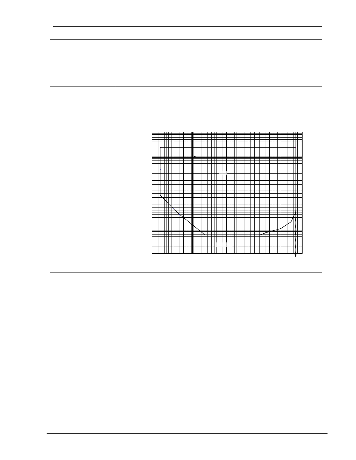
Input signal for adaptive
trigger min. 57mVpp
(+/-10%) 20mV
RMS
• Max. Voltage: 80V
• DC- decoupling
• The Trigger level automatically adapts itself to the input signal in the range
+28.5mV to +2V. The Adaptive Trigger improves the signal to noise immunity
(226Vpp)
RMS
e.g. where electromagnetic sensors are used.
1000.00
100.00
10.00
Min. Trigger level: 57 mVpp +/-10% = 20 mV
+/-10% U min. = f(Frequency)
RMS
O.K
1.00
Sensor Signal (Vpp)
0.10
NOT O . K.
0.01
0.01
0.1
1
10
Frequency (Hz)
100
1000
10000
100000
3
Page 8
Operating Instructions SWT-2000 DYNALCO
Input signal for adaptive
trigger min. 500mVpp
(+/-10%) 180mV
RMS
• Max. Voltage: 80V
• DC- decoupling
• The Trigger level automatically adapts itself to the input signal in the range
(226Vpp)
RMS
+250mV to +2V. The Adaptive Trigger improves the signal to noise immunity
e.g. where electromagnetic sensors are used.
Min. Trigger level: 500 mVpp +/-10% = 180 mV
1000.0
100.0
10.0
Sensor Signal (V pp)
1.0
+/-10% U min. = f(Frequency)
RMS
O.K.
Sensor supply
NOT O . K.
0.1
0.01
0.1
1
10
Frequency (Hz)
100
1000
10000
• +14V +/- 0.5V, max. 35mA / Short circuit proof
• If the current limit has been activated, then the circuit needs to be
disconnected to reset the protection.
Typical voltage curve as a function of sensor current
14.8
14.6
14.4
14.2
Sensor voltage (V)
14.0
13.8
Sensor voltage = f (Sensor current)
100000
13.6
0 5 10 15 20 25 30 35 40 45
Sensor current (mA)
Integral pull up resistor
1000Ω to +14V (Only for 2 wire active e.g. NAMUR sensors)
Screen Terminals are provided for each sensor cable screen (Sh1 and Sh2). These
terminals are internally connected to the sensor input / supply 0V.
4
Page 9
Operating Instructions SWT-2000 DYNALCO
Sensor monitoring 3 sensor monitoring settings are available in the configuration software:
• No Sensor Monitoring
• Monitoring of supplied sensors (active Sensor Types)
[Also for 2 wire sensors that are supplied via the internal Pull-up resistor (1kΩ)
Æ Sensors drawing current outside of I
= 0.5…35mA
I
min
I
= 0.5…35mA
max
min
or I
are considered to be faulty.
max
• Monitoring of non powered sensors (passive Sensor Types)
[For 2 wire sensors such as electromagnetic sensors.]
Æ The sensor is considered to be faulty if the line is broken.
Here the sensor impedance is dynamically measured.
Z < 60 kΩ = OK
Z > 125 kΩ = NOT OK
2.3 Binary Inputs
Number 2 Active Binary Inputs and 1 push button (FUNC – logic OR with Binary input B1)
Level Logic 0 = 0V….+5V
Logic 1 = +15V….+36V
Isolation voltage 1500 V
Input resistance
R
min
RMS
= 8.2 kΩ
2.4 Outputs
2.4.1 Analog Outputs
Number 2 Analog outputs
Isolation voltage 1000 VDC
Output type Current (selectable 0…20 / 4…20mA)
Load
Open circuit voltage Max. 15V
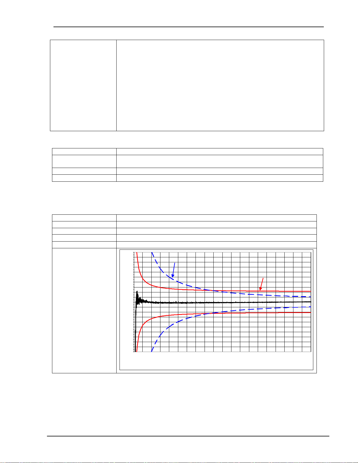
Typical error curve
Max. 500Ω
1
0.9
0.8
0.7
0.6
0.5
0.4
0.3
0.2
0.1
0
-0.1
-0.2
-0.3
Measurement error (% )
-0.4
-0.5
-0.6
-0.7
-0.8
-0.9
-1
0.00E+00
CLASS 0.1 % (from End Value)
1.00E-03
2.00E-03
3.00E-03
4.00E-03
5.00E-03
6.00E-03
7.00E-03
8.00E-03
0.2 % (from measured value) + 2 LSB
9.00E-03
1.00E-02
1.10E-02
1.20E-02
1.30E-02
1.40E-02
I (A)
1.50E-02
1.60E-02
1.70E-02
1.80E-02
1.90E-02
2.00E-02
5
Page 10
Operating Instructions SWT-2000 DYNALCO
0
Mode
[mA]
21
20.5
2
12
Mode
4...20mA
Fai l ur e le vel
0 … 20mA
4
2
0
Startvalue Endvalue
0...20mA
Transfer Functions Start value < or > End value
Startvalue < Endvalue
Output
Outputvalue
Output
Resolution 14 Bit (16384 increments)
Max. Linearity error 2 LSB (Least Significant Bit) ca. 2.7uA
Measuring error Max. 0.15 % f.m.v. + 2 LSB (-25°C Æ +50°C)
Max. 0.20 % f.m.v. + 2 LSB (-40°C Æ +70°C)
Accuracy class 0.1 % of the end value
Damping Hardware time constant T = 4.1 ms
10% Æ90% = 8.6 ms (Hardware)
Actual time = Hardware time constant + Software setting (configuration)
Temperature Drift Typ.: 50 ppm/K, max. 120 ppm/K
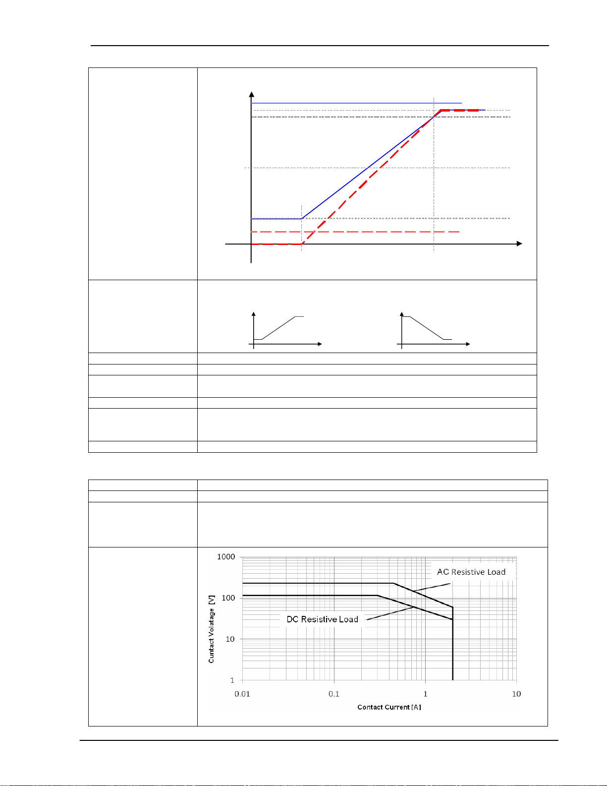
2.4.2 Rela ys Outputs
Number 4
Type Single Pole Double Throw (SPDT)
Functions
Relay - max. switching
current
• May be assigned to System Limit 1..6, Sensor Alarm, Static error Sensor 1 or
2, dynamic error, always on or off.
• With or without Hold function (Reset via Binary input)
• Fail Safe or Not Fail Safe
Startvalue > Endvalue
Outputvalue
Fe hler level
4 … 20mA
Output
Value
6
Page 11

Operating Instructions SWT-2000 DYNALCO
Reaction time Effective Measurement interval + max 6 ms
Contact resistance
Contact isolation 1500 VAC (coil to contact)
50 mΩ Max. (Initial contact)
1000 VAC (between open contacts)
2.4.3 Open Collector Outputs
Number 2 Open Collector outputs
Type Opto-coupler (passive)
External resistance IC nominal = 15mA (R
IC max. = 30mA
Reaction time
Load voltage V = 5VDC…36VDC
Isolation voltage 1500 VAC
Functions
Inverting Open collector output frequencies are in phase with the input signal.
• As Frequency output: <30 us
• Effective Measurement interval + max 30 us
• May be assigned to System Limit 1..6, Sensor Alarm, Static error Sensor 1 or
2, dynamic error, always on or off.
• With or without Hold function (Reset via Binary input)
• Frequency Sensor 1 or 2, Frequency x2, Frequency x4 (subject to phase shift)
• Fail Safe or Not Fail Safe
= V / I) Example: V = 24 V
Pull-up
Æ
R = 1.6 kΩ
2.5 Data Communication
2.5.1 Ethernet
Number 1
Physical Layer Ethernet 10Base-T, IEEE 802.3i
Max cable length 100 m
Transmission rate 10 MBit/s
Connection Front panel, 8P8C (RJ45)
Usage Configuration and measurement status
Protocol Peer to Peer
Connecting cable Use a crossover cable
2.6 Environment
2.6.1 Climatic Conditions
Standard DIN 40 040
Operating temperature See 2.1 General
Storage temperature See 2.1 General
Relative Humidity
2.6.2 Elec tromagnetic Immunity
Electrostatic discharge EN 61000-4-2 Contact 6 kV, air 8 kV
Electromagnetic fields
Fast transients EN 61000-4-4 2 kV, repeated 5 kHz duration 15 ms period 300 ms
Slow transients EN 61000-4-5 Line / line +/- 1kV, earth line +/- 2kV, 1 per minute
Conducted HF EN 61000-4-6 3 V eff (180 dBuV) 10 kHz – 80 MHz
Mains frequency
Magnetic field
Voltage dips
• 75% average over 1 year; to 90% for max. 30 days.
• Condensation to be avoided.
EN 61000-4-3
EN 61000-4-8 50 Hz, 100 A/m 2 minutes
EN 61000-4-11
30 V/m, not modulated and AM 80 % with 1000Hz Sinus
wave
Voltage dips, short interruptions and voltage variations
immunity tests
7
Page 12

Operating Instructions SWT-2000 DYNALCO
3. Principle of Operation
3.1 General
The model SWT-2000 is microprocessor controlled and operates in accordance with the period measurement
principle whereby the duration of the input period is measured during the measurement interval. The reciprocal
value based on the average input period corresponds to frequency and hence speed. The relationship
between frequency and speed is determined by the Machine Factor.
The status of System Limits is based on various inputs that can be logically combined AND or OR. System
Limit inputs may be: both speed inputs, a Math function based on the speed inputs and, the 2 binary inputs. A
hysteresis may be set for the speed inputs and Math function individually. The 6 System Limits in each of 4
parameter sets may be individually defined. Parameter sets may be selected via binary inputs. The 4 relays
and 2 open collector outputs may be assigned to any System Limit and will react accordingly. The 2 open
collectors may alternatively be assigned to frequency x1, x2 or x4. Relay and open collector status may be
latched and then reset via binary input.
The system permanently monitors itself. Sensors may in addition be monitored. Sensor error may be used in
the configuration to influence System Limits. System error would influence the relays, open collectors and
Analog outputs and the front panel LED would go out.
Frequency outputs (Open Collector Outputs) are not influenced by the Machine factor but correspond to the
input signal. For frequency X2 or X4 the 2 input signals should ideally be phase shifted by 90 degrees.
Parameter input is via resident PC software and the Ethernet Interface. This may also be used to interrogate
the unit, display measurement and unit status.
The Parameters are safely stored in EEPROM.
3.2 Machine Factor
The machine factor establishes the relationship between sensor frequency (Hz) and corresponding speed
(RPM).
Machine Factor = Frequency
RPM
If the # gear teeth and RPM are known, use the following formula to calculate corresponding frequency:
Signal Frequency (Hz) = (RPM) X (Teeth or Discontinuities)
60
Another way to calculate the machine factor is:
Machine Factor = (Teeth or Discontinuities)
60
Note: The above formulas are based on the gear or target turning at the same speed as the machine being
monitored, ie: no step up or step down gear ratios involved.
8
Page 13

Operating Instructions SWT-2000 DYNALCO
4. Installation
The SWT-2000 may only be installed by competent personnel. Only undamaged and correctly configured units
may be used.
Before switching on, check that the supply is within the permissible range.
The Sensor cable screens must be connected terminals „Sh1“ and „Sh2“ respectively so as to minimize the
effects of signal noise. These terminals are internally connected with 0V.
Attention: If the password has been changed, there is no way of returning to a factory setup. If the password
is forgotten, the unit will need to be returned to Dynalco for re-programming.
5. Connections
5.1 Front View
5.1.1 Front View SWT-2000
Terminal B
Terminal A
The Ethernet Interface, status LED along with the FUNC push button are located at the front. For
communications, see Paragraph 6 Configuration via PC Software
9
Page 14
Operating Instructions SWT-2000 DYNALCO
V
A
A
V
V
A
A
V
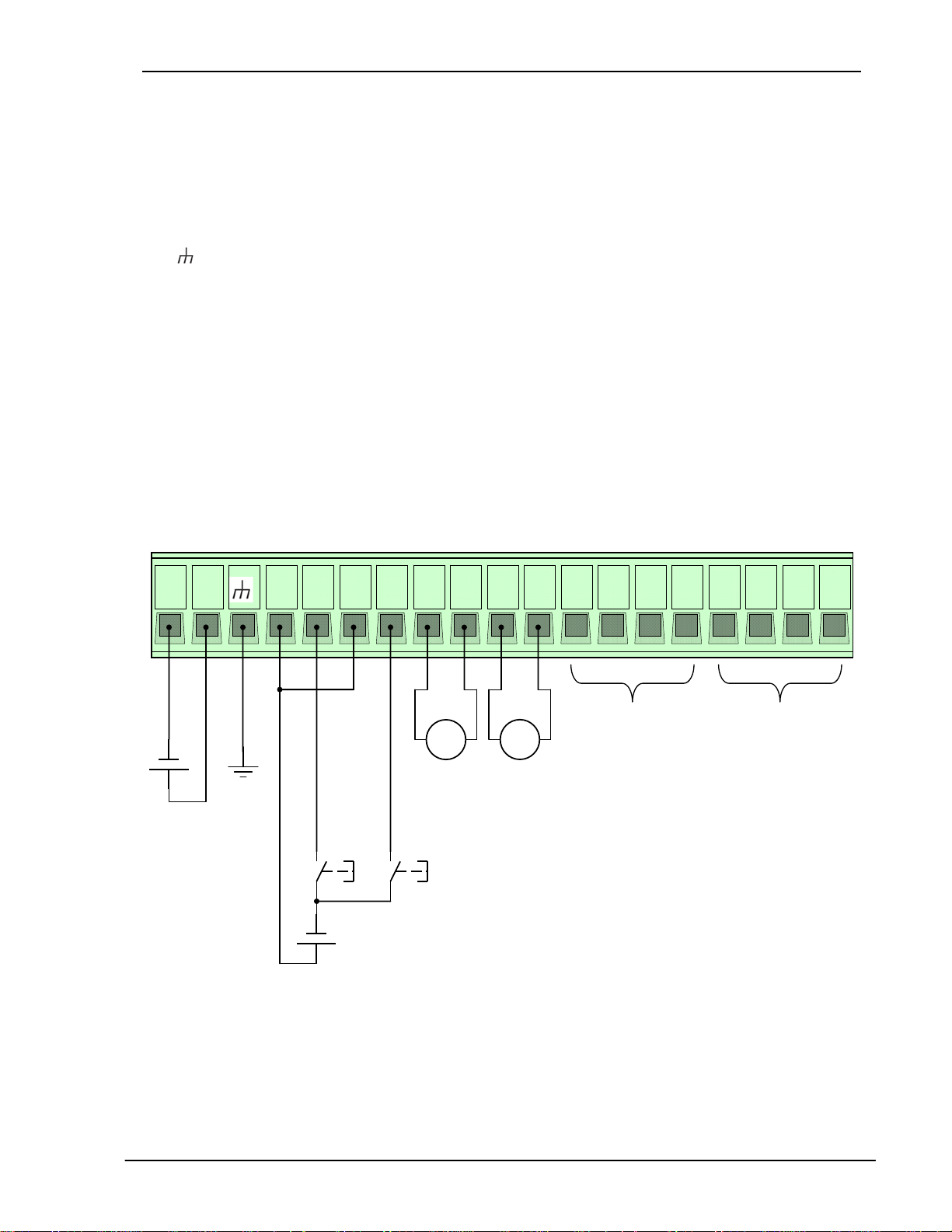
5.1.2 Terminal A
Supply
+ : Input Supply (+)
- : Input Supply (-)
: Earth
Sensor connections S1 / S2
S1 : Sensor input S1
Sh1 : Screen S1
V1+ : Sensor Supply S1
V1- : 0V S1
S2 : Sensor input S2
Sh2 : Screen S2
V2+ : Sensor Supply S2
V2- : 0V S2
+ -
B1 - B1
+
B2 - B2
O1
O1
-
+
+
Binary Inputs
B1+ : positive B1
B1- : negative B1
B2+ : positive B2
B2- : negative B2
Analog outputs
AO1+ : positive I1
AO1- : negative I1
AO2+ : positive I2
AO2- : negative I2
O2
O2+ Sh1
-
1- S1
Sh2
1
+
2
S2
-
2
+
+
-
Power supply
+
-
-
AO1 AO2
Current output
B2B1
Binary input
-
+
+
Sensor 1
Sensor 2
10
Page 15

Operating Instructions SWT-2000 DYNALCO
5.1.3 Terminal B
Open Collector Outputs Oc1 / Oc2
OC1+ : positive Open Collector 1 (Emitter)
OC1- : negative Open Collector 1 (Collector)
OC2+ : positive Open Collector 2 (Emitter)
OC2- : negative Open Collector 2 (Collector)
Relay output
Relay Outputs R1-R4
NC : Normally closed
NO : Normally open
Com : Common
com
R1
R1
no
R1
nc
R2
com
R2
no
com
R2
nc R3com
nc
no
R3
no R3nc
R4
comR4no R4nc
+
=
-
OC1- OC1+ OC2
-
Open Collector 1
Open Collector 2
OC2
+
11
Page 16

Operating Instructions SWT-2000 DYNALCO
6. Configuration via PC Software
6.1 Software Concept
The SWT-2000 Ethernet connection is used to configure or interrogate the unit. (see Paragraph 9
Accessories) The resident menu driven configuration software is used for unit set up.
Normal PC file handling procedures apply and the configuration file can be communicated between computer
and SWT-2000.
To run the Software you must have Java Runtime Environment (JRE) 1.5 or higher.
6.2 PC Settings
The PC Ethernet card must first be set correctly. SWT-2000’s cannot be used on a network.
Go to Desktop, Settings, Network connections and right click on <Properties>. Right click the Network card
you want to use for SWT-2000 comms and select <Properties>.
Select Internet protocol (TCP/IP) and select the Option <IP-Address automatically recognize>
6.3 Download Configuration Software
Connect the Tachometer to your PC using a cross over patch cable. Once connected open your browser and
enter the IP address 192.168.1.127/software
An HTML page will open with the Link <Download control program>
Click on the Link. Dependent upon your Internet Explorer configuration you will be asked whether you want to
<Open> (Run) or <Save> (Save as) the program.
Direct Execution
Select <Open> and the configuration will be read from the tachometer (can take a few seconds). Once loaded
the configuration software will open automatically.
Save As
Select <Save> to save the file in a path of your choice (can take a few seconds).
Open the file from your PC. The configuration software establishes a connection to the SWT-2000 and reads
the actual parameters.
12
Page 17

Operating Instructions SWT-2000 DYNALCO
6.4 Configuration Software
Configuration User and Process User
SWT-2000 parameters are divided into 2 groups, Configuration and Process parameters.
When the program is started, the window shows 3 log in levels, Config user, Process user or Guest. Process
and Configuration users require passwords.
As a Guest one only has the right to view measured data or print out actual parameters.
A Process user can perform Guest functions and view and change Process parameters.
The Configuration user has full access and control over all Parameters, Process as well as Configuration.
The factory settings are shown below Bold.
6.4.2 Log in
Here you can Log in on three different levels. The standart passwords for Config- and Process- User are:
Config user password
Process user password
1981
1977
6.4.3 Main Window an d System L imit Matrix
After successfully logging in you will see the main window used for displaying system and measurement
status.
On the left the various System Limit inputs are listed. In the middle the System Limit and alarm status are
shown and on the right all outputs and current levels can be seen.
In the middle is a bar called System limit Matrix. Click on this and an overview of the logical status of System
Limits, binary inputs and sensor error is shown.
6.4.4 Logging In and Out
To change user level log out via <File> and click on <Log out>, then log in again using the appropriate
password.
6.5 Configuration File
6.5.1 …cre ating new
To create a new configuration file go to <File>, <New> and click on OK. All parameters are then reset.
Note: If you have not saved the live parameters, they will be lost.
13
Page 18

Operating Instructions SWT-2000 DYNALCO
6.5.2 …resetting to factory default
To reset parameters to factory settings go to <Settings> <Back to factory setup> then click on OK.
Note: If you have not saved the live parameters, they will be lost.
6.5.3 …load ing
To load an existing file go to <File>, <Open> and select the required configuration file.
Note: If you have not saved the live parameters, they will be lost.
6.5.4 …saving
To save actual parameters go to <File>, <Save as> and choose the path and file name you want to use.
Please note that the file name ends in the format *. SWT-2000.
6.5.5 …printout
To print actual parameters go to <File>, <Print> and choose your printer. 9 pages will be printed.
6.6 Communication with the SWT-2000
6.6.1 Read Measured Data
To read actual measured data and unit status go to <Online>, <Start – read measure data>.
Measured data is updated in the Main window with interval defined under <Settings>, <Refresh Interval>.
¼ Second
½ Second
1 Second
2 ½ Seconds
5 Seconds
10 Seconds
To end the measured data display go to <Online>, <Stop – read measure data>.
6.6.2 Reading Configuration from the SWT-2000
When the configuration software is started the configuration file is automatically transferred to the PC. To up
load the file again go to <Online>, <Read parameters> and confirm with Enter.
Note: The live parameter data will be overwritten.
14
Page 19

Operating Instructions SWT-2000 DYNALCO
6.6.3 Writing a Configuration to the SWT-2000
When a new configuration file is ready it can be downloaded into the tachometer. Go to <Online>, <Write
Parameters> Enter. The new Parameters are then transferred to the Tachometer (can take 10s.). If no
connection can be established this will be aborted after 3 attempts.
Note: The actual file in the tachometer will be overwritten.
6.6.4 Comp are Data
If you would like to compare a PC configuration file with that in the SWT-2000, first open the file and then go
to <Online>, <Compare Data>.
The actual file is then uploaded from the SWT-2000 and compared with the software parameters. A dialogue
window will then appear showing whether the files are identical or not.
6.7 Configuring
The factory defaults are written in bold.
6.7.1 Speed Sens o rs
Go to <Configuration>, <Sensor>.
To connect the sensor see Paragraph 5 Connections.
5 Parameters are used to configure the sensor:
Type: powered / not powered
Resistor: activated / deactivated
Min. current: 0.5mA … 35mA
Max. current: 0.5mA … 35mA
Trigger level: fixed 3V / min 57mV
Sensor Type
Powered:
The sensor is supplied from the SWT-2000’s 14V (+/-0.5V) supply. To use static sensor
monitoring, the Min/Max current consumption must be defined.
Not powered:
The sensor is not powered by the SWT-2000 and no static monitoring is possible.
Internal pull up resistor
Deactivated:
The internal pull up is not in circuit.
Activated:
The internal pull up is in circuit.
/ min 500mV
pp
pp
Current monitoring
When the sensor is supplied from the tachometer upper and lower current limits must be entered. Current
consumption outside of the defined limits results in a static sensor error being signaled.
Trigger level
One of 3 modes may be selected. Fixed Trigger (fixed 3V) for digital sensors and two adaptive Triggers
(57 mV
/ 500 mVpp) for Analog speed sensors (electromagnetic).
pp
15
Page 20

Operating Instructions SWT-2000 DYNALCO
6.7.2 Binary Input Configuration
To configure binary inputs go to <Configuration>, <Binary>.
The following options are available for each binary input:
Logic level: Active high / Active low
Function of binary input: Input for System Limit / Selection of Control (A/B) (C/D) / Reset latch
Logic level definition
Active High:
Active Low:
Binary input for
System Limit input:
Binary input is a constituent part of System Limits.
Parameter set selection:
Binary inputs select the parameter set (PS), see Paragraph 7.3.2 Parameter sets A, B, C and D
Reset latch:
Binary input resets the relays and open collectors.
Logic 1 = binary input 15V …33V
Logic 1 = binary input 0V … 5V
6.7.3 Set Measuremen t Interval
Go to <Configuration>, <Measurement time>.
This time interval determines the period during which the speed, parameters, status and outputs are
recalculated and set accordingly.
Measurement time: 2ms / 5ms / 10ms / 20ms / 50ms /
100ms / 200ms / 500ms / 1s / 2s / 5s
6.7.4 Sensor Alarm
Go to <Configuration>, <Sensor alarm>.
There are 3 sources of errors which may be OR
Static error sensor 1: On / Off
Static error sensor 2: On / Off
Dynamic error: On / Off
Box checked = On, unchecked = Off
(see also Paragraph 6.7.1 Speed sensors).
Dynamic Error can only be used when 2 sensors are present. (see Paragraph 6.7.6 Dynamic Error).
ed together. Each error source may be included or excluded.
16
Page 21

Operating Instructions SWT-2000 DYNALCO
6.7.5 Machine Factor
Go to <Configuration>, <System>.
The Machine factor establishes the relationship between sensor frequency and associated machine speed.
(see Paragraph 3.2 Machine factor)
The Machine factor may also be set by means of the number of pulses per rev. The 2 parameters have a
fixed relationship of factor 60 (Pulses per rev. = Machine factor x 60)
Machine factor: 0.0001 … 1 … 999,999
Pulses per revolution: 0.006 … 60 … 59,999,940
Once the machine factor has been established all further entries such as speed limits are in machine units
e.g. rpm.
6.7.6 Dyna mic Error
Go to <Configuration>, <System>.
: Sensor 1 frequency
f
Difference
This function is only available when both sensor inputs are used. This function has influence only on Sensor
alarm.
Deviation: 0.0 … 100.0 … 999,999
If the speed difference is greater, then Dynamic error is signalled.
−=
ff
S1
: Sensor 2 frequency
f
S2
SS
21
17
Page 22

Operating Instructions SWT-2000 DYNALCO
6.7.7 Math Function
Go to <Configuration>, <Math>.
Math function is an additional input available for System Limit.
The following Math functions may be constructed.
S1 – S2
S2 – S1
S1 / S2
S2 / S1
100% x (S1-S2)/S2
100% x (S2-S1)/S1
Variance (S1)
Variance (S2)
Acceleration (S1)
Acceleration (S2)
S1
S2
Percentage difference
)12(100
nn −×
1
n
Variance
1
2
=
S j = 100
Acceleration
a
−
j
v
Δ
=
=
n: Speed
j
∑
ix
1
=
1
i
Δ
If the variance for S1, S2 or Analog input needs to be calculated, the measurement time must be set to 5ms
or higher.
Subtraction of speed values
Division of speed values
Percentage difference
Variance
Speed value acceleration
The speed values are fed through
e.g. for the Math function.
2
)(
−
xx
−
alt
11
ttnt
−
n: Speed
altFlankeSFlankeS
11
18
Page 23

Operating Instructions SWT-2000 DYNALCO
6.7.8 System Limit
Go to <Configuration>, <System Limits>.
Every System Limit has the same 5 logic inputs: Sensor 1, Sensor 2, Math function, Binary input 1, Binary
input 2. A hysteresis may be applied to the first 3. Each may be inverted or selected to form part of a logical
combination or disabled. The logical combination of inputs may be OR or AND.
Sensor alarm may be additionally combined OR with the System Limit result.
Sensor 1:
Limit low: 0.01 … 200.0 … 999,999
Limit high: 0.01 … 300.0 … 999,999
Sensor 2
Limit low: 0.01 … 400.0 … 999,999
Limit high: 0.01 … 500.0 … 999,999
Math Function
Limit low: -999,999 … 50.0 … 999,999
Limit high: -999,999 … 100.0 … 999,999
Inversion:
Sensor 1: Over speed / Under speed
Sensor 2: Over speed / Under speed
Math: Over-run / Under-run
Binary input 1: active / inactive
Binary input 2: active / inactive
Inclusion in logical combination:
Sensor 1: On / Off System Limit 1
Sensor 2: On / Off System Limit 2
Math: On / Off System Limit 3
Binary input 1: On / Off System Limit 4
Binary input 2: On / Off System Limit 4
Logical combination:
Combined OR / AND
Hysteresis
Hysteresis may be definined for the first 3 inputs via upper and lower limits. If the lower limit is set higher than
the upper limit, the hysteresis is inverted.
Inversion
Every input may be inverted.
Logical combination
The box must be ticked to include the input in the logical combination.
Sensor Alarm
To OR Sensor alarm with the System Limit result the box must be ticked.
19
Page 24

Operating Instructions SWT-2000 DYNALCO
6.7.9 Relay Outputs
To configure relay outputs go to <Configuration>, <Relay / Open Collector>.
Relay configuration consists of:
Assignment, the Latch Function and the Fail safe/Not fail safe mode.
Possible relay assignment:
Latch Function: Latched / not latched
Safety function: Fail safe / Not fail safe
Assignment selection
The selection box is used to choose relay assignment.
Latch Function
Defines whether a relay state should be held until reset.
Safety Function
Defines whether the relay is to operate in Fail safe (deactivate at limit) or not fail safe mode (activate at limit).
System limit 1
System limit 2
System limit 3
System limit 4
System limit 5 Always ON
System limit 6 Always OFF
Sensor Error
Static S1
Static S2
Dynamic error
6.7.10 Open Collector Outputs
To configure Open Collector outputs go to <Configuration>, <Relay / Open Collector>.
Open Collector configuration consists of:
Assignment, the Latch Function and the Fail safe/Not fail safe mode.
Possible Open Collector assignment:
System Limit 1 Static S2
System Limit 2 Dynamic error
System Limit 3 Always ON
System Limit 4 Always OFF
System Limit 5
System Limit 6
Sensor Error Frequency x2
Static S1 Frequency x4
Latch Function: Latched / not latched
Safety mode: Fail safe / Not fail safe
Assignmment selection
The selection box is used to choose Open Collector assignment.
Latch Function
Frequency S1
Frequency S2
20
Page 25

Operating Instructions SWT-2000 DYNALCO
Defines whether an Open Collector state should be held until reset.
Safety Function
Defines whether the Open Collector is to operate in Fail safe (deactivate at limit) or not fail safe mode
(activate at limit).
6.7.11 Analog Output
To configure Analog outputs go to <Configuration>, <Analog out>.
4 parameters are available: Assignment, Current range, Start and End values and the time constant.
Assignment possibilities:
Sensor 1
Sensor 2
Math value
Current range: 0 ..20mA / 4 .. 20mA
Start value: -999,999 … 0.0 … +999,999
End value: -999,999 … 2.000.0 … +999’999
Time constant 0 … 9.9 in 0.1 Second increments
Assignment selection
The selection box is used to choose Analog Output assignment.
Current range
0 … 20mA or 4 … 20mA
Start and End values
Enter the start and end values e.g.
0 (rpm) = 4mA
2000 (rpm) = 20mA
If the end value is lower than the start value, the output current follows a falling characteristic.
Time constant
Sets a time constant T. The target value is reached after 5xT.
The output current follows an e- Function.
Analog output 1
Analog output 2
21
Page 26

Operating Instructions SWT-2000 DYNALCO
6.7.12 Copy P arameter Set
Go to <Configuration>, <Copy from Control A>.
A Parameter set may only be copied from Parameter set A. The following Parameters will be copied:
- Machine factor 1 and 2
- Difference
- Math Function selection
- Upper and Lower Limits in System Limits
- System Limit inversion
- Inclusion of input in the logical combination
- Inclusion of Sensor alarm in the logical combination
- Relay / Open Collector assignment
- Relay / Open Collector latch mode
- Relay / Open Collector fail safe mode
- Analog output assignment
- 0..20mA or 4..20mA setting
- Start and End values
- Analog output time constant
6.7.13 Change-Over Delay
Go to <Configuration>, <Delay>.
One change-over delay may be set for the delay in switching from Parameter set B to Parameter set A only.
Delay time: 0 … 2000 Seconds
Only integer values can be used for the change-over delay.
6.8 Settings
6.8.1 Ethernet Interface
Go to <Settings>, <Interface …>.
No settings can be made. The PC- SWT-2000 connection is Peer to Peer
(PC to PC). SWT-2000’s cannot be connected to a network!
For technical data see Paragraph 2.5.1 Ethernet.
DHCP Server ON / OFF
TCP/IP Adresse 192.168.1.127
TCP/IP Maske 255.255.255.0
22
Page 27

Operating Instructions SWT-2000 DYNALCO
6.8.2 Changi n g the Password
Go to <Settings>, <Change Config user password> or <Change Process user password>.
Changing the password involves entering the old password and the new password twice. To save the
password click on <OK>.
The password is now stored in the configuration software.
To change it in the SWT-2000 the data must be downloaded.
A Configuration user may change the Process user password by entering the Configuration user password
first. Factory set passwords:
Config User:
Process User
Attention: If the password has been changed, there is no way of returning to a factory setup. If the password
is forgotten, the SWT-2000 will need to be returned to Dynalco to be reset.
1981
1977
6.9 Info
To gain information about the SWT-2000 or to enter a Process name <Info>, <Info about>.
An individual Process name may be entered into the text field to the right of <Process ID>, max. 16
characters. (Only alphanumeric characters).
Type: Tachometer type number
Java version: Java Version stored in the Tachometer
Firmware: SWT-2000 Firmware Version
Serial Nr: SWT-2000’s serial no.
Cal. Date: Calibration date
TCP/IP Address: SWT-2000’s IP Address
JRE Version: PC’s JAVA Runtime
23
Page 28

Operating Instructions SWT-2000 DYNALCO
7. Operating Behavior
7.1 Power On
The parameter set e.g. as defined by binary inputs is immediately valid.
7.1.1 Analog Output
Immediately after power on, the output corresponds to the lower range value set. Following the first
measurement interval the output corresponds to the measured value.
7.1.2 Relay Output
Up until the first measurement interval is completed, all relays are de-energiZed. Thereafter they assume the
defined condition.
If no input frequency is present then after measurement interval x 2, 0Hz is assumed.
7.1.3 Open Collector Output
Up until the first measurement interval is completed, all Open Collectors are inactive. Thereafter they assume
the defined condition.
If the Open Collector is assigned to a frequency, then it immediately assumes the corresponding status.
If no input frequency is present, then after measurement interval x 2, 0Hz is assumed.
24
Page 29

Operating Instructions SWT-2000 DYNALCO
7.2 Frequency Measurement
Every frequency measurement starts with the negative edge of the input signal. The last measured edge prior
the end of the measurement interval completes the running measurement and immediately starts the next.
An optimum measurement is achieved when the input period is shorter than the measurement interval.
Input signal
End of the measurement interval
Input period
Measurement
Time
If the input period is greater than the measurement interval, the frequency is calculated as follows:
f
=
1
n: Number of measurement intervals without input signal
nt
×
tMeasuremen
This continues until a second negative edge arrives.
End of the measurement interval
Input signal
Input period
Measurement
Time
The calculation and adjustment of outputs occurs immediately after the start of the next measurement interval.
If the input frequency is lower than the lower limit (0.025Hz), then the output will be zero. The measurement of
input frequencies above the upper limit (50kHz) is not guaranteed.
7.2.1 The Adaptive Trigger Level
The trigger level is continuously adjusted for
successive pulses. This guarantees that the trigger
level can follow a 50% reduction in speed from pulse
to pulse. DC offset, resonance and negative pulses
have no effect on the triggering
U
Old Triggerlevel
Triggerlevel
t
signal to
noise ratio
bad
Sensorsignal
25
Page 30

Operating Instructions SWT-2000 DYNALCO
7.2.2 Sign al Failur e
Signal failure is defined as the sudden transition from an input frequency to no further recognisable pulses.
The frequency is then calculated as follows:
f
=
The measured speed thereby follows an exponential function to the minimum frequency (0.025Hz) and then
falls to zero.
1
n: the number of measurement intervals without an input signal
nt
×
tMeasuremen
7.3 Functions
7.3.1 “FUNC ” Push Button
The front panel “FUNC“ button is ORed with binary input B1. Pushing this button executes the B1 function.
7.3.2 Parameter Sets A , B, C and D
The binary inputs must be used to change parameter sets. To configure binary inputs see paragraph 6.7.2.
Binary input configur.
Binary input configuration
Binary input 1 to <Selection of Control A/B>
Binary input 2 not to parameter set selection
Binary input 1 not to parameter set selection
Binary input 2 to <Selection of Control C/D>
Binary input 1 to <Parameter set selection A/B> and
Binary input 2 to <Parameter set selection C/D>
For delay in switching between Parameter sets B and A see Paragraph 6.7.13 Change-over delay.
Status
BIN 1
0 X A
1 X B
X 0 C
X 1 D
0 0 A
0 1 B
1 0 C
1 1 D
Status
BIN 2
Selected
Parameter set
7.3.3 Limits
User defined upper and lower limits allow wide or narrow hysteresis to be set. Unless otherwise required we
recommend a hysteresis of 10%.
26
Page 31

Operating Instructions SWT-2000 DYNALCO
7.3.4 Math Function
To set a Math function on a speed input please follow the steps below. (Example for Sensor 1):
1. Set the Math function to S1.
2. Set Math function and Sensor 1 hysteresis.
3. The Sensor – hysteresis gets the higher limit.
4. Math function must be set to under run.
5. All logic inputs must be switched off except Sensor 1 and Math function.
6. The two inputs must be combined OR.
System limit settings
27
Page 32

Operating Instructions SWT-2000 DYNALCO
7.3.5 Frequency X2 and X4
Prerequisites for the X2 and X4 function are that the input frequencies are synchronized, they exhibit
approximately 90 degrees phase shift and a Mark : Space ratio of approximately 1:1.
The X2 function is an EXOR combination of input frequencies S1 and S2. The X2 output frequency can reach
a max value of 35KHz.
The x4 function is based on doubling of the X2 frequency and generates a 10us output pulse each time a
positive or negative X2 edge is detected.
The Mark : Space ratio thereby changes with frequency. The x4 output frequency can reach a max value of
35KHz.
Frequency S1
90°
Frequency S2
Frequency X2
Frequency X4
10us
7.3.6 Rela y and Open Col lector Latch Function
Relays and Open Collectors can be assigned a latch function. If a signal arrives from the assigned function the
relay / OC is latched and remains latched until reset via binary input or the <FUNC> button.
Where fail safe mode is selected the deactivated Relay / Open Collector state is held.
7.3.7 Analog Output
If an analog time constant higher than zero is set, with measurement interval of 2ms, then the max.
frequency that can be measured is 35KHz.
To measure frequencies higher than 35KHz with time constant higher than zero, a min. measurement
interval of 5ms must be selected.
If Sensor Alarm is active that influences the analog output, which assumes the error condition:
Configuration Output current
0 .. 20mA 21mA
4 .. 20mA 4mA
28
Page 33

Operating Instructions SWT-2000 DYNALCO
7.3.8 Interpretation of System Limit Inputs
Upper and lower set points may be set for each of the 3 system limit inputs. In this way a hysteresis is defined.
If the upper set point is exceeded then this input assumes a status of 1. When the lower set point is then
passed, the status returns to 0. If the actual value lies between the 2 set points then the status is as before.
If a parameters set change takes place when the actual value lies between the set points, the status also
remains as before.
7.4 Fault Behavior
7.4.1 Sensor Error
The sensors may be monitored in 3 ways.
• Sensor powered by the SWT-2000 – Sensor supply current monitoring.
If the current falls outside of the defined range, a static error is signalled.
• Sensor not powered by the SWT-2000 – wire break detection.
Static error is signalled when wire breakage occurs. (Impedance measurement of 2 wire sensor)
• 2 speed sensors connected – Dynamic sensor monitoring, i.e. the 2 signals may be compared. If the
values differ by more than the defined tolerance, dynamic error is signalled.
The SWT-2000 behaviour in the event of a sensor fault is a function of the software configuration. If sensor
monitoring is selected, a fault causes the LED to go off and the analog output (both) go to error status. The
Relay and open collector behavior is a function of the configuration.
7.4.2 System Alarm
The microprocessor continuously monitors the following functions for errors: Supply, math functions of the
micro controller, RAM, EEPROM.
In the event of a fault the relays are de-activated, the current output goes to 2mA (4-20mA) or 21mA
respectively and the Open Collectors become high resistance if assigned to a function other than frequency
output. The SWT-2000 then initializes and attempts to run again.
7.5 Power Failure
If the power fails for longer than the bridging time, the outputs are de-activated, i.e. Analog outputs go to 0mA,
relays de-activate and the Open Collectors go to high resistance.
As soon as the supply returns to the minimum required, the SWT-2000 commences its initialization routine.
7.6 Behavior During Configuration
During the transmission of configuration or process parameters to the tachometer, it goes into a safe mode,
i.e. the outputs assume a defined state. For individual outputs that means:
• Relays: are no longer powered
• Open Collectors: become high resistance
• Analog outputs: assume the fault mode according to the configuration
29
Page 34

Operating Instructions SWT-2000 DYNALCO
8. Mechanical Construction / Housing
Dimensions
8.2 Mounting
Wall mounting Top hat rail mounting
(as delivered)
30
Page 35

Operating Instructions SWT-2000 DYNALCO
9. Accessories
Interface Cable PC – SWT-2000 (6 Ft crossover): Part No. 270A-105039
31
 Loading...