

Page 1
SWT-1000
Speed Switch / Transmitter
Operating Manual
3690 NW 53rd Street • Fort Lauderdale, FL 33309 • Ph 954-739-4300 • Fax 954-4 86 -4968 • www.dynalco.com
Page 2

TABLE OF CONTENTS
1. Product Features 1
2. Specifications 2
2.1 General 2
2.2 Inputs 3
2.2.1 Analog Sensor Connection (Sign) 3
2.2.2 Digital Sensor Connection (IQ) 4
2.2.3 Binary Input and Push Button 4
2.3 Outputs 5
2.3.1 Analog Output 5
2.3.2 Relay 6
2.3.3 Open Collector Output 6
2.4 Data Communication 6
2.4.1 Serial Interface (RS 232) 6
2.5 Environment 6
2.5.1 Climatic Conditions 6
3. Principle of Operation 7
3.1 General 7
3.2 Machine Factor 8
4. Installation 9
5. Connections 9
6. Hardware Configuration 10
6.1 Analog Sensor Input (Sign) 10
6.2 Digital Sensor Input (IQ) 10
7. Configuration with PC Software 11
7.1 Software Concept 11
7.2 PC Communications 13
7.3 PC Software Settings 11
7.3.1 Interface (Settings Æ Interface) 11
7.3.2 Display Interval (Settings Æ Di splay Int erval) 11
7.4 Parameter List and Ranges 12
7.5 Parameters 14
7.5.1 System Parameters (Configuration Æ System) 13
7.5.2 Sensor Parameters (Configuration Æ Sensor) 13
7.5.3 Analog Output (Configuration Æ Anal og Output) 14
7.5.4 Limits (Configuration Æ Limits) 15
7.5.5 Relay Parameter and Selection of Parameter Set 15
8. Operating Behavior 17
8.1 Power On 17
8.1.1 Analog Output 17
8.1.2 Relay Output 17
8.2 Measurement 17
8.2.1 The Adaptive Trigger Level 17
8.2.2 Signal Failure 18
8.3 Functions 18
8.3.1 Limits and Window Function 18
8.3.2 Parameter Sets A and B 18
8.3.3 Relay Hold Function 18
8.3.4 Push-Button 18
8.3.5 Binary Input 19
8.4 Fault Behavior 19
8.4.1 Sensor Fault (Sensor monitoring) 19
8.4.2 System Alarm 19
8.4.3 Alarm 19
8.5 Power Supply Interruption 20
9. Mechanical Construction / Housing 20
10. Accessories 20
11. Outline Dimensions 20
Page 3

Operating Instructions SWT-1000 DYNALCO
1. Product Features
The model SWT-1000 speed switch / transmitter measures and monitors frequencies (speed
proportional values) in the range 0 to 35,000 Hz.
The following are available:
• 1 Current output
• 1 Sensor frequency output
• 1 Relay
• 2 Limits
• 2 Parameter sets – selectable via binary input
• Sensor monitoring
• System monitoring
The tachometers are configured via SWT -1000 PC configuration software.
All settings are in revolutions per minute (RPM).
Single channel tachometer, relay and 0/ 4-2 0mA current output
SWT-1000.r2.0609 1
Page 4
Operating Instructions SWT-1000 DYNALCO
2. Specifications
2.1 General
SWT-1000
Lowest measuring
range
Highest measuring
range
Minimum response time
(Fix Time)
Effective Measuring
time
0.01 . . . 1.000 Hz
0.01 . . . 35.00 KHz
Selectable values: 2 / 5 / 10 / 20 / 50 / 100 / 200 / 500 ms
1 / 2 / 5 Seconds.
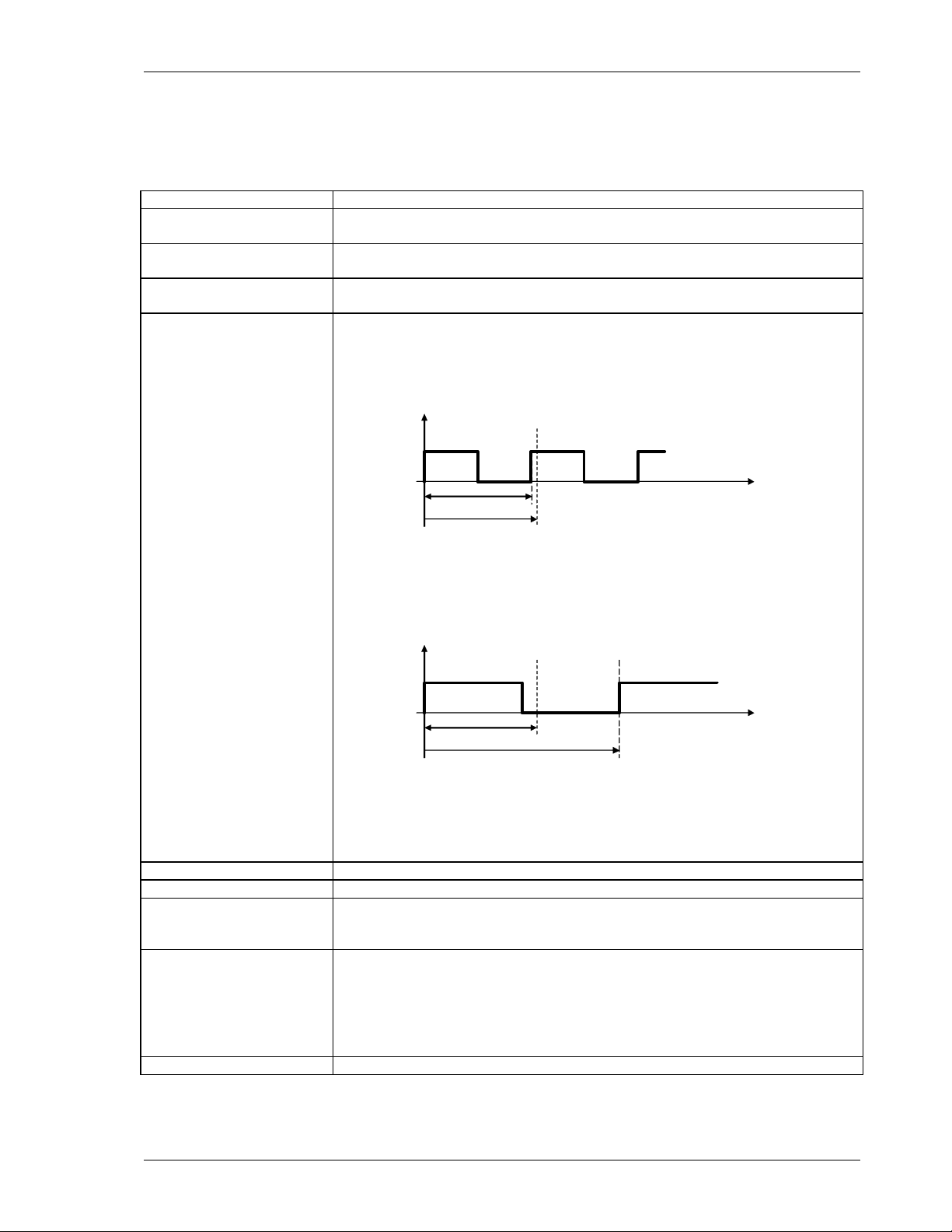
Is based on the minimum measuring time (Fix Time) and the measured
frequency.
• Input frequency period < Fix Time
Input
frequency
End of Fix Time
Input period
Fix Time
typically: t
max: t
= Fix Time
effective
= 2 x Fix Time
max
• Input frequency period > Fix Time
Input
frequency
End of Fix Time Ensuing edge
Fix Time time
Period of input signal
max: t
max
• In the event of sensor signal failure:
t
= Fix Time + (2 x last input frequency period)
effective
Resolution 0.05 %
Power supply range 10...36 VDC
Power consumption 10 V : 2.3 W
24 V : 2.6 W
36 V : 3.0 W
Isolation Galvanic isolation between:
• Power supply,
• Sensor input incl. sensor supply, Binary input, Seria l i n te rfa ce
• Analog output
• Relay output
• Open collector output
Isolation voltage 700 VDC / 500VAC
time
= 2 x input frequency period
SWT-1000.r2.0609 2
Page 5
Operating Instructions SWT-1000 DYNALCO
2.2 Inputs
2.2.1 Analog Sensor Connection (Sign)
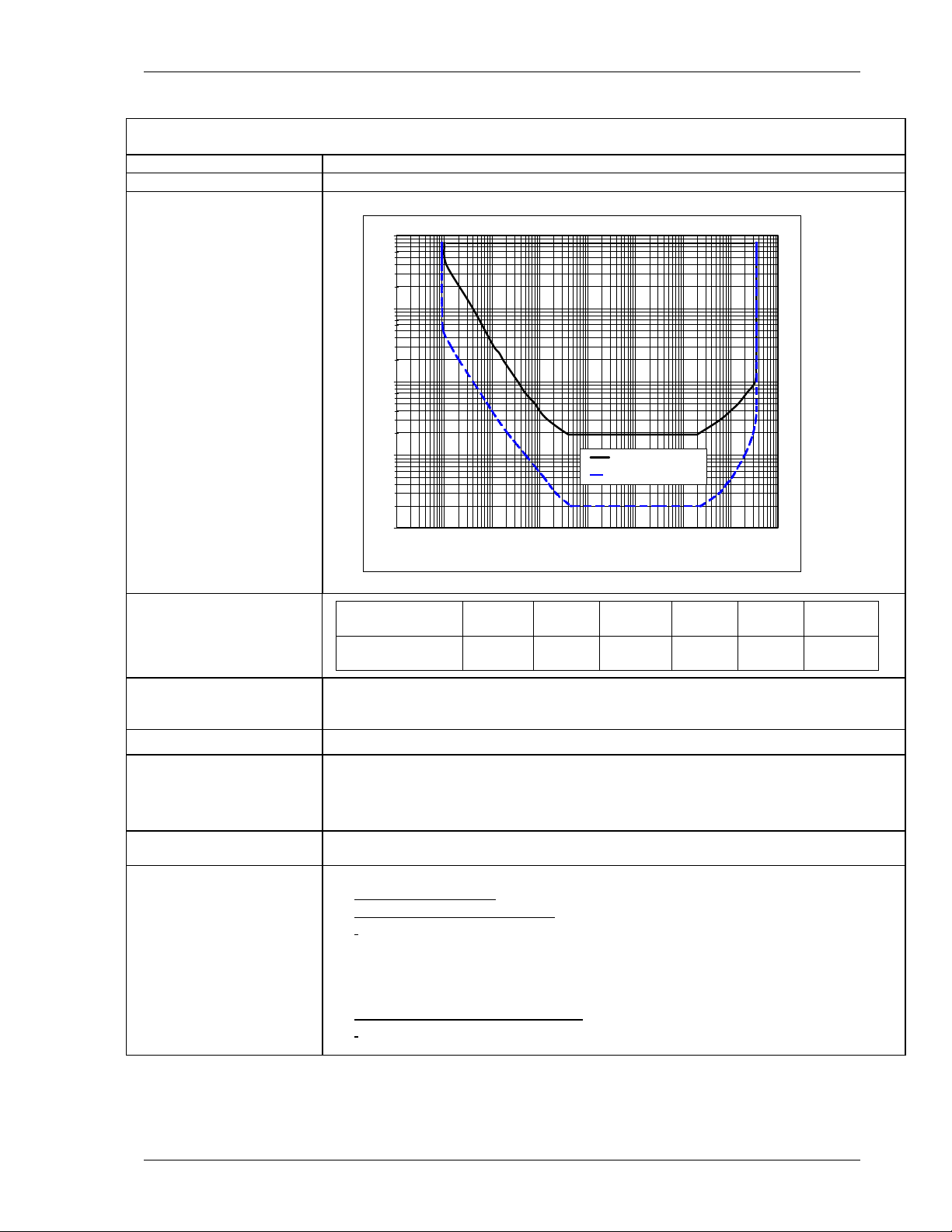
Frequency range (-3dB) 0.01 Hz / 35 kHz
Input impedance 30kOhm
Input voltage
• Max. 80V
•
100
10
Input voltage [Veff]
rms
Max. frequency against input voltage
O.K.
1
0.001
]
pp
NOT O.K.
0.01
0.1
1
10
Frequency [Hz]
Trigger: 500mVpp
Trigger: 20mVeff
100
1000
10000
100000
0.5 1 2.5 5 10 20
2000 667 333 200 166 125
Minimum positive pulse
width - digital signals
Input voltage
0.01
Signal
voltage [V
Min. Pulse
width [µs]
0.1
Sensor supply +14 V, max. 35 mA short circuit proof.
If the current limit activates, the sensor supply must be disconnected to reset the
protection.
Integrated pull-up 820 Ohm to +14V (configurable for 2 wire sensors with Jumper J1)
Trigger level Adaptive trigger level.
Configurable with Jumper J2:
• 250mV … 6.5V (>500mVpp) [Factory configuration]
• 28mV … 6.5V (>20mV
rms
)
Screen A terminal is provided for the sensor cable scre en. Th is terminal is connected to the
sensor supply 0V. (0VS)
Sensor monitoring 1 of 3 sett i ng s ma y be con figured via software:
• No Sensor Monitoring
• Monitoring of powered sensors
Also for 2 wire sensors supplied via the Pull-up resistor (Jumper J1)].
[
Æ The sensor is considered to be defectiv e if the sensor current consumption
falls outside of I
I
= 0.5…25mA
min.
= 0.5…25mA
I
max.
min
and I
• Monitoring of non powered sensors
For 2 wire sensors such as electromagnetic sensors.]
[
max
.
Æ The sensor is considered to be defective if the circuit is disconnected.
SWT-1000.r2.0609 3
Page 6

Operating Instructions SWT-1000 DYNALCO
2.2.2 Digital Sensor Connection (IQ)
Frequency range (-3dB) 0.01 Hz / 35 kHz
Input impedance 46 K
Input voltage Max. ± 36V peek
Minimum pulse width Min. pulse width 1.5 µs
Sensor supply +14 V, max. 35 mA short circuit proof.
If the current limit activates, the sensor supply must be disconnected to
reset the protection.
Trigger level
Screen A terminal is provided for the sensor cable screen. This terminal is
Sensor monitoring 1 of 2 settings may be configured via software:
• min.U
• max.U
low
high
= 1.6 V
= 4.5 V
connected to the sensor supply 0V. (0VS)
• No Sensor Monitoring
• Monitoring of powered sensors
Also for 2 wire sensors supplied via the Pull-up resistor (Jumper J1)
[
].
Æ The sensor is considered to be defective if the sensor cu rr ent
consumption falls outside of I
= 0.5…25mA
I
min.
I
= 0.5…25mA
max.
min
and I
max
.
2.2.3 Binary Input and Push Button
Use For external selectio n of Parameter set A or B.
• Logic 1 = Parameter set A (Relay control A)
• Logic 0 = Parameter set B (Relay control B)
Levels Logic 1 = V > +3.5V
Logic 0 = V < +1.5V
Reference Sensor supply 0V
Max voltage 36V
Input resistance
Circuit Internal pull up resistance to 5V
R
= 10kΩ
min
Shorting the binary input to the sensor 0V
creates logic 0.
parameter set A B
+Bin
pushbutton
OVS
5 volts
SWT-1000
analysis
SWT-1000.r2.0609 4
Page 7
Operating Instructions SWT-1000 DYNALCO
2.3 Outputs
2.3.1 Analog Output
Type Current
Load Max. 500 ohms
Open circuit voltage Max. 12V
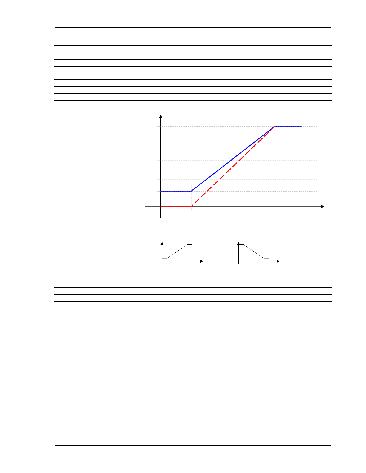
Operating Mode
SWT-1000
0…20 / 4…20mA
[mA]
21
20
12
4
0
4...20mA mode
0...20mA mode
initial value final value
Transfer functions Normal or Inverse (rising or falling characteristic)
output
„normal“
speed
output
„invers“
Resolution 12 Bit (4096 Steps)
Max Linear error 0.1 %
Accuracy 0.5 % of the full range value.
Damping Hardware 11 ms + Software setting (Configuration)
Temperature Drift
Typically ± 100 ppm/K, max. ± 300 ppm/K
Reaction time Effective measuring time + 7.5ms
(minimal measured
speed
value)
speed
[rpm]
SWT-1000.r2.0609 5
Page 8

Operating Instructions SWT-1000 DYNALCO
2.3.2 Relay
Type Single Pole Double Throw
Limit Hysteresis Programmable – 1 lower and 1 upper set point per limit.
Functions 2 programmable parameter sets select a ble via binary input
• Reaction to Alarm, Sensor fault, Limit, always on or off.
• “Normal“ or “Inverse“ (normally de-ene r gized or energized)
• With or without ‘Hold function’ (Reset via Binary input )
Accuracy 0.05% of the value set
Temperature tolerance
Reaction time Effective me asur ement time + 10.5ms
Contact rating AC: max. 250 VAC, 1250VA.
Contact isolation 1500 VAC
Max. ± 10ppm of the value set
DC:
2.3.3 Open Collector Output
Type Opto-coupler (passive)
External Pull-up R = 143 x V (Ic nominal = 7 mA)
R = 91 x V (Ic nominal = 11 mA)
Load voltage V = 5 – 30V
Max load current 25mA
Isolation 1500VAC
2.4 Data Communication
2.4.1 Serial Interface (RS 232)
Physical Layer Similar to EIA RS 232 but with +5V CMOS Level
Max cable length 2 m
Transmission rate 2400 Baud
Connection Front panel, 3.5mm jack plug
2.5 Environment
2.5.1 Climatic Conditions
Operating temperature - 40 ... + 85 °C
Storage temperature - 40 ... + 90 °C
Relative humidity 75% averaged over the year; up to 90% for max 30 da ys.
Condensation to be avoided.
SWT-1000.r2.0609 6
Page 9

Operating Instructions SWT-1000 DYNALCO
X
2
3. Principle of Operation
3.1 General
The SWT-1000 is controlled by a micropro ce ssor . It works according to the period measu rem ent
principle whereby the input period is measu r ed with subsequent computing of the reciprocal value
corresponding to the frequency or speed. The relationship between frequency and speed is
established with the Machine factor.
The current output and relay cont rol a re de te rmined from the speed. The relay function is defin ed
via 2 selectable parameter sets. Each parameter set can ac ce ss the 2 limit values, the alarm
definition, sensor monitoring and other process values. The 2 limits each have and upper and
lower set point (hysteresis setting). The selection of the valid parameter set is via the binary i np ut .
The relay status may be held until reset via the binary input
The system continuously monitors itself. In addition, the sensor may be moni tored. Dependent
upon the configuration, these co nditions can influence the relay and current output.
The alarm status is indicated via the front panel LED.
The frequency output (open colle ctor output) is not influenced by the machine factor and
corresponds to the input signal frequency.
The input of all parameters is via PC software and the RS232 interface. This may also be used to
interrogate the unit’s settings, measurement and general status.
Parameters are retained in an EEPROM.
binary
input
Analysis of the
binary input
Reset
Choice of the parameter set A/B
Push-Button
Sensor
connection
Sensor suppl y
Sensor control
Periodic time
measurement
EEPROM
RS 232
Frequency
calculation
Sensor failure
Frequency
System control
Machine
factor
System failure
Speed
Definition Alarm
Definition limit 1
Definition limit
Definition current output
Definition
Relay
LED
Relay
Current
output
Open
Collector
SWT-1000.r2.0609 7
Page 10

Operating Instructions SWT-1000 DYNALCO
3.2 Machine factor
The machine factor establishes the relati on sh ip between sensor frequency (Hz) and corresponding
speed (RPM).
Machine Factor = Frequency
RPM
If the # gear teeth and RPM are known, use the fol l o wing formula to calculate corresponding
frequency:
Signal Frequency (Hz) = (RPM) X (Teeth or Discontinuities)
60
Another way to calculate the machine f a cto r is :
Machine Factor = (Teeth or Discontinuities)
60
Note: The above formulas are base d on the gear or target turning at the same speed as t he
machine being monitored, ie: no step up or step down gear ratios involved.
SWT-1000.r2.0609 8
Page 11

Operating Instructions SWT-1000 DYNALCO
4. Installation
The SWT-1000 may only be installed by trained and comp e ten t pe r so nnel. An undamaged SWT1000, valid configuration and suitable in sta llation are required.
The power to the SWT-1000 should be capable of being disconnected via a switch or other
emergency means.
Before switching the equipment on, the power supply voltage should be verified t o be in the
permissible range.
The sensor cable screen must be connected to the terminal ‘Sh’ so as to minimize the influence of
noise. This terminal is directly connected int ern ally to 0VS.
5. Connections
Front view SWT-1000
Sensor connections
Sh : Screen - Sensor cable
0VS : Sensor reference voltage
+V Out : Sensor Supply
Ana. : Sensor signal analog
Dig. : Sensor signal digital
Pulsed Output
+ PO : Open Collector Output
- PO : Signal reference for the Open Collector
Relay output:
NC : Normally closed
NO : Normally open
COM : Common
Analog Output:
+ AO : Current positive
- AO : Current negative
Supply:
+24V : Power (10 ... 36 V)
GND : Power reference
: Earth
SWT-1000.r2.0609 9
Page 12

Operating Instructions SWT-1000 DYNALCO
6. Hardware Configuration
6.1 Analog Sensor Input (Sign)
Jumper
position
J1: Sensor type
2 wire sensors
(with 820Ohm Pull Up resistance)
J1
J2
J2: Adaptive trigger level
range
28mV to 6.5V (>20mV
rms
)
3 wire and electromagnetic sensors
(factory setting)
250mV to 6.5V
(>500mVpp)
[factory setting]
6.2 Digital Sensor Input (IQ)
No hardware configuration neces sary.
SWT-1000.r2.0609 10
Page 13

Operating Instructions SWT-1000 DYNALCO
7. Configuration with PC Software
7.1 Software Concept
All settings are written via PC to the SWT-1000 usin g t he RS232 interface and the aid of the user
friendly menu driven SWT-1000 software.
The parameter file may be stored, op en ed , printed and exchanged between the SWT- 100 0 a nd a
PC.
7.2 PC Communications
Communications with the SWT-1000 are init iat ed by the PC via the RS232 interface.
Prior to starting comms, Settings Æ Interface must be set to an appropriate serial interface.
The following settings also apply:
Transmission rate: 2400 Baud
Parity Bit: none
Data Bits: 8
Stop Bits: 2
Connector: 3.5mm jack plug
5 1
female
2
3
5
TXD
RXD
GND
TXD RXDGND
9
6
The diagram shows the stereo jack plug to D9 connections.
The tachometer RXD must be connected to t he PC’s TXD and vi ce ve rsa.
The SWT-1000 does not use a standard RS232 signal (-5V…+5V) but operates at 5V CMOS
levels, compatible with most PC’s as long as the cable is not longer than 2m.
A suitable cable may be ordered from DYNALCO – see sect ion 1 0 .
7.3 PC Software Settings
Interface (Settings Æ Interface)
In this menu the serial interface for comms with t he SWT-1000 is defined.
Display Interval (Settings Æ Display Interval)
The SWT-1000 measurement status may be inte rro gated and displayed on the PC via SWT-1000
Æ Start – Reading Measure Data.
The display update time may be set at intervals of ¼ to 10 seconds.
SWT-1000.r2.0609 11
Page 14

Operating Instructions SWT-1000 DYNALCO
7.4 Parameter List and Ranges
If you already have a configuration file you can open and view it using the SWT-1000 Wi nd ow s
Software menu
File Æ Open
You can also connect the SWT-1000 to a PC (see sect io n 7.2 ) an d r ea d ba c k t he parameters,
SWT-1000 Æ Read parameters
Once loaded into the software the parameter set may be printed via File Æ Print
Normal Windows file handling rules appl y .
7.5 Parameters
Parameters are changed in the sub menus fro m the d ro p do wn menu “Configuration“. Paramete r
list and ranges. Factory settings are shown in bold.
Configuration < System >
Machine factor 1.0000E-07 ... 1.0000 .. . 9.9 999E+07
Minimum Measuring time 2 / 5 / 10 / 20 / 50/ 100 / 200 / 500 ms / 1/ 2 / 5 Seconds
Min displayed measured value 1.0000E-12 ... 1 ... 1.0000E+12
Alarm definition Only System error System error OR Sensor Monitoring
Configuration < Sensor >
Sensor Type Active / Passive
Sensor input Analog (Sign) / Digital (IQ)
Sensor current minimum 0.5 ... 1.5 ... 25.0mA
Sensor current maximum 0.5 ... 25.0mA
Configuration < Analog output >
Measuring range start value 0.0000 ... 90% of the end value
Measuring range end value 1 … 2000.0 … 500000
Output range 0 ... 20mA / 4 ... 20mA
Time constant (Damping) 0.0 ... 9.9s
Configuration < Limits >
Status Limit 1 On / Off
Status Limit 2 On / Off
Mode Limit 1 Normal / Inverse
Mode Limit 2 Normal / Inverse
Lower Set point Limit 1 0.1 … 200.00 … 500000
Upper Set point Limit 1 0.1 … 300.00 … 500000
Lower Set point Limit 2 0.1 … 400.00 … 500000
Upper Set point Limit 2 0.1 … 500.00 … 500000
Configuration < Relay control >
Switching of control A/B
Selection of actuator None (always control A) / Binary Input B1
Delay time 0 ... 2.000 s
Relay Assignment
Control A Alarm / Sensor monitor / Limit 1 / Limit 2 / Window / On /
Off
Acknowledge A Without acknowledge (no hold function) /
Relay held when control active /
Relay held when control inactive
Acknowledge B Alarm / Sensor monitor / Limit 1 / Limit 2 / Window / On /
Off
Acknowledge B Without acknowledge (no hold function) /
Relay held when control active /
Relay held when control inactive
SWT-1000.r2.0609 12
Page 15

Operating Instructions SWT-1000 DYNALCO
Warning:
New configurations only become active af te r being d o wnl oad ed into the SWT-1000 via:
SWT-1000 Æ Write Parameters
7.5.1 System Parameters (Configuration Æ System)
Machine Factor
The machine factor establishes the relationship between s ensor frequency and associated speed.
Machine Factor = Frequency
RPM
See section
3.2 Machine factor.
Once the correct machine factor is enter ed, all ot her settings e.g limits are made in RPM.
Minimum Measuring Time
The minimum measuring time determines the ti me dur in g whi ch the input frequency is measured.
Once this time has lapsed, the calculation is made following the end of the running signal perio d.
The minimum measuring time may be increased to filter out frequency jitter so as to display a
stable reading but at the cost of increased reaction time.
Minimum Displayed Value
The minimum displayed value is a measured value under wh ich “0 0 00” is displayed.
Alarm Definition
This function defines the alarm. It may be only system error or a logical OR combination of
system error OR sensor monitoring. During an alarm the LED is off. In addition, the relay is
deactivated and the analog outpu t goes to 0mA irrespective of the output range.
7.5.2 Sensor Parameters (Configuration Æ Sensor)
Sensor Type
The type of sensor to be used is defined here.
<Sensor active>
supplied via the internal pull up resistor. (Jumper J1).
<Sensor passive>
See also section 8.4.1 Sensor Fault (Sensor monitoring).
Sensor Input
The sensor input “analog” (Sign) or “digital” (IQ) is defined here.
Sensor Current Minimum
As long as the sensor current consumption lies abov e the value <Current Minimum>, the sensor
is considered to be functioning correctly.
Sensor Current Maximum
As long as the sensor current consumption lies below the value <Current Maximum>, the sensor
is considered to be functioning correctly.
SWT-1000.r2.0609 13
is for monitoring sensors powered by SWT-1000 including 2 wire sensors
is for monitoring non powered sensors e.g. 2 wi re VR (pa ssive) sensors.
Page 16

Operating Instructions SWT-1000 DYNALCO
7.5.3 Analog Output (Configuration Æ Analog Output)
[mA]
21
20
4...20mA mode
12
(minimal measured
value)
4
0...20mA mode
0
initial value final value
speed
[RPM]
Measuring range – start value
Analog output start value 0 or 4mA
Measuring range – end value
Analog output end value 20mA
In the case of a negative transfer function the end value must be set smaller than the start value.
Output range
0…20mA or 4…20mA
Output time constant
The analog output signal may be smoothed by applying a software time constant. This damping is
deactivated when the time constant is 0. 0 seconds.
SWT-1000.r2.0609 14
Page 17

Operating Instructions SWT-1000 DYNALCO
t
7.5.4 Limits (Configuration Æ Limits)
The SWT-1000 series offers 2 independent limits Æ Limit 1 and 2.
Status
Limits are selected here. If the limit is deactivated, the other values such as set points and mode
have no further effect.
Mode
In Normal Mode the limit is active as soon as the High set po int is exceeded. In Inverse Mode the
limit is active from the start (zero speed) and deactivates when t he set point is reached (Fail Safe
operation)
Upper and Lower Setpoint
limi
activated
switching point
lower
upper
switching point
deactivated
As the speed increases, the limit switches when the High set point is rea che d a nd remains in that
condition until the speed reduces past the Low set point.
7.5.5 Relay Parameter and Selection of Parameter Set
(Configuration Æ Relay control)
Parameter set A / B selection
With standard factory setting, paramet e r set B may be acti v at ed via the binary input <Binary input
B1>. If parameter set B is to be deactivated, this setting should be none (always control A)
Delay time when switching A <- B
This value determines the delay from switching the binary input to the switching from parameter
set B to parameter set A.
Relay assignment with control A
Defines the relay behavior in parameter set A.
Relay assignment with control B
Defines the relay behavior in parameter set B.
Relay
Defines the source information for relay swit chin g.
Status
Relay dependency
register
Alarm (Common) Alarm [7.5.1 System Parameters (Configuration Æ
System)]
Sensor monitor Sensor status (7.5.2 Sensor Parameters (Configuration Æ
Sensor))
Limit 1/2 Selection of Limit ½ (
7.5.4 Limits (Configuration Æ Limits)
Window ExOR combination of both limits
On The relay is on
Off The relay is always off
Acknowledge
Acknowledge establishes if and under what conditions the relay status is held. A relay that is held
no longer reacts to the assigned signal a nd ca n only be reset via the binary input.
RPM
SWT-1000.r2.0609 15
Page 18

Operating Instructions SWT-1000 DYNALCO
SWT-1000.r2.0609 16
Page 19

Operating Instructions SWT-1000 DYNALCO
8. Operating Behavior
8.1 Power On
8.1.1 Analog Output
Following power on the output assume s t he out put range start value. Upon completion of the f i rst
measurement the output goes to the corresponding measured value.
Relay Output
The parameter set determined by the configur at io n an d bin ary input is valid from the start.
If the relay is assigned to a limit it remains deactivated until completion of the first measurement,
following which it assumes the status defined und er Li mit .
If the relay is assigned to any other item in the status regi ste r it immediately assumes the
corresponding status.
If no input frequency is present then after a period of 2 x Fixtime a measured value below the
lower set point is assumed.
8.2 Measurement
Every measurement begins with the positive edge of the input signal. Once the Fixtime has lapsed
the next positive edge ends the running measurement and starts the next.
The resulting effective measurement time is dependent upon whether the input sign a l peri od is
longer or shorter than the Fixtime.
Input signal period < Fixtime Input signal period > Fixtime
End of Fixtime Ensuing edge
Input
Frequency
Input period time
Fixtime
Effective measurement period
t
Measurement typically
t
Measurement max
= Fixtime
= 2 x Fixtime
The total measurement time has a resolution of ± 0.4 μs. The calcu lation and adaptation of
outputs follows immediately after the Fixtime. With inpu t frequencies outside of the measuring
range, the corresponding final values ar e assumed.
8.2.1 The Adaptive Trigger Level
After triggering, the trigger level is set for the
next pulse anew.
This guarantees that the trigger level can follow
a 50% reduction in speed from pulse to pulse.
DC offset, resonance and negative pu lses have
no influence on the triggering
Input
Frequency
t
Measurement max
U
End of Fixtime Ensuing edge
Fixtime time
Period of input signal
Effective measurement period
Fixtime
= 2 x Input signal period
old trigger level
trigger level
signal to
noise ration
bad sensor
signal
t
SWT-1000.r2.0609 17
Page 20

Operating Instructions SWT-1000 DYNALCO
8.2.2 Signal Failure
In the event of a sudden loss of a good signal, no po sit iv e edg e arrives to complete the
measurement or start a new one. Once the minimum measur e me nt time (Fixtime) has lapsed the
unit waits for twice the last measurement period f ollo wi ng whi ch h a l f th e last mea s ure d speed is
assumed. If the signal remains missing then the measurement approaches zero.
8.3 Functions
8.3.1 Limits and Window Function
Since the upper and lower sets points are freely selectable a large hysteresis may be set. If that is
not necessary we recommend setting a 10% hysteresis.
The Window function allows an Exclusive OR combin a tio n of Limit s 1 and 2, w hereby the status of
both limits is first determined (including any inv ersion) and a subsequent ExOR comparison
executed.
As soon as Relay assignment is <Window> the relay behaves as follows:
• With identical limit modes (both Normal or both Inverse) the relay is activated when the
measured value lies between the Limit 1 and 2 setti ng s.
• If different modes are set (one Normal and the other Inverse) the relay is deactivated when
the measured value is between Limts 1 and 2.
8.3.2 Parameter Sets A and B
The SWT-1000 has 2 parameter sets availab le th at d efine the relay assignment. Parameter set A
would normally be used. If another pa rameter set is needed, e.g. for test purposes, the binary
input may be used to change to parameter set B. Th e tran sfe r from parameter set B to parameter
set A may be delayed in the range 0 to 2000 seconds. Transferring from A to B is however
immediate and not affected by this setting.
To be able to select parameter sets using the binary input, Relay control - Selection of Actuator
must be appropriately set.
Binary input condition Selected Parameter set
High (5V) “normal“ A
Low (0V) “connected to 0V“ B
8.3.3 Relay Hold Function
A latch function may be assigned to the relay. By selecting <Relay is hold if control is active> the
relay is activated once the assigned limit is active and remains held even if the input frequency
would no longer cause a trip. By selecting <Relay is hold if contr o l is inacti ve>, the deactivared
state of the relay is held. The latched status ma y be re set by cycling power or via the binary input,
whereby the binary input must be activat ed as p er the configuration (0V or 5V) for between 0.1
and 0.3 seconds.
8.3.4 Push-Button
The front panel push button internally connects the binary input to 0VS thus generating a logic 0.
SWT-1000.r2.0609 18
Page 21

Operating Instructions SWT-1000 DYNALCO
8.3.5 Binary Input
2 functions are executable using the binary inp ut:
• Switching between parameter sets A and B. S ee 8. 3.2 Paramet e r Sets A and B.
• Resetting a latched relay. See 8.3.3 Rela.
The binary input has an internal pull up resistor to +5 V and is therefore normally logic High.
Shorting the binary input to the sensor supply 0V creates a logic 0.
5 Volt
SWT-1000
Switching the input for between 0.1 and 0. 3 seon ds r esets a
latched relay but does not influence para meter set selection, which
requires longer than 0.3 seconds.
parameter set A B
+Bin
pushbutton
OVS
10k
analysis
8.4 Fault Behavior
8.4.1 Sensor Fault (Sensor monitoring)
The sensor may be monitored in 2 ways. With sensor s powered by the SWT-1000 the sensor
supply current is monitored. If the curren t f alls out side t he permit ted range then sensor fault is
indicated.
If the sensor is not powered by the SWT-1000 then it may only be monit ored for disconnection. If
disconnected, sensor fault is indicated.
The SWT-1000 behavior in the event of a sensor fault is dependent on the configuration:
Alarm Configuration
Only System error
System error OR Sensor monitoring
Outputs in the event of a sensor fault
LED
Analog output
Current
On Measured value output per configuration
Off 0mA Deactivated
8.4.2 System Alarm
If the microprocessor detects a checksum faul t (RAM, ROM or EEPROM ) th e measured value is
set to 0 RPM, The analog output goes to 0/4mA and the relay is deactivated.
Alarm Configuration
Only System error
System error OR Sensor monitoring
Outputs in the event of a System alarm
LED
Analog output
Current
Off 0mA Deactivated
Relay
Relay
8.4.3 Alarm
As long as a combined alarm is present, no measuremen ts a re conducted and the outputs behave
as described above. Once the fault or alarm condition is removed the last correct measured value
is assumed. Eventual limit activation is not taken into acc ount .
SWT-1000.r2.0609 19
Page 22

Operating Instructions SWT-1000 DYNALCO
8.5 Power Supply Interruption
If input power remains off for longer than the permitted period the outputs deactivate i.e. the analog
output goes to 0mA, the relay deactivates and the “open collector“ output becomes high resistance.
Once the supply resumes in range the SWT-1000 begins its initialization routine.
9. Mechanical Construction / Housing
The housing features front plugab le te rminals that are protected from accidental cont a ct. The rear is
designed for mounting onto a DIN rail.
10. Accessories
Interface Cable PC – SWT-1000, Part No. PC-T400
SWT-1000.r2.0609 20
 Loading...