

Page 1

SW-50 Speed Switch
Installation and Calibration Instructions
Installation: Mount the SW-50 to a secure bracket off the engine. If on-engine
mounting is necessary , shock mounts are recommended. Wire according
to connection diagram on reverse. Shielded cable is recommended. Shield
should be brought to ground directly. The SW-50 will work with most
magnetic pickups provided the signal amplitude is greater than 50 mVrms
and less than 70 Vrms. Mount pickup according to manufacturer’s
instructions.
Calibration: Determine the setpoint frequencies from an RPM value using
the following formula:
Frequency =
Verify current calibration: Connect a signal generator — such as the Dynalco
F-16 — to the SW-50 magnetic pickup input (signal input).
J Set the signal generator to a low frequency . Slowly increase the frequency .
Using an ohmmeter across each relay contact, in turn, determine the
frequency at which the relays change state. (Note: overspeed relay will
latch if terminal 4 is not grounded.)
Change the setpoints: Remove the screws in the access holes for the relay
adjustment trim pots.
J Set the signal generator to the frequency at which the relay should change
state.
J Using a small, flat screwdriver, adjust the trim pot for the appropriate relay
until the relay changes state.
J Decrease the frequency , then slowly increase it to verify that the relay trips
at the appropriate point.
RPM x No. of Teeth (Holes)
60
DYNALCO CONTROLS RESERVES THE RIGHT TO CHANGE THESE SPECIFICATIONS WITHOUT NOTICE.
3690 N.W. 53rd Street, Fort Lauderdale, FL 33309 U.S.A.
(
954) 739-4300 • Fax: (954) 484-3376 • Web site: www.dynalco.com
©2002 Azonix-Dynalco Available at <www.dynalco.com> Select: Downloads 145f-12043, REV 0
SW-50 is a trademark of Dynalco Controls
Page 2
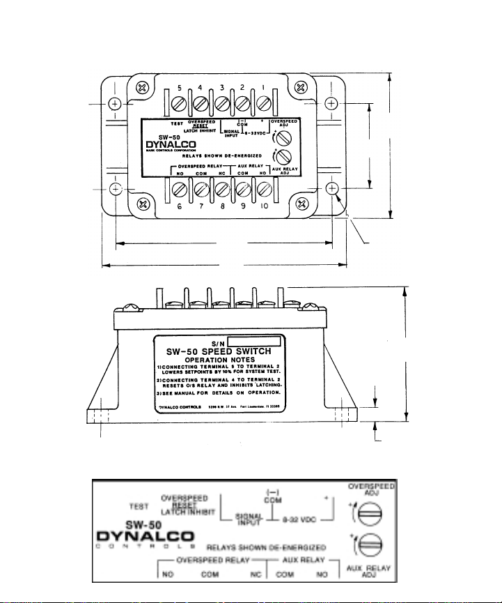
SW-50
CONNECTION DRAWING
2.00
(5.1)
3.12
(7.9)
4.62
(11.7)
5.12
(13.0)
.25
(.64) DIA
.25
(.64 )
3.75
(9.5 )
Dimensions
inches
(centimeters)
 Loading...