

Page 1
5450 NW 33rd Ave, Suite 104
Fort Lauderdale, FL 33309
3211 Fruitland Ave
Los Angeles, CA 90058
SST7000
SST7100
Speed Switch / Transmitter
Installation and Operation Manual
Rev. C
P/N145F-13112
PCO – 00009270
(c) Copyright 2014, Dynalco Controls
All Rights Reserved
Published: April 29, 2015
Page 2

IMPORTANT - PLEASE READ BEFORE PROCEEDING!
The Dynalco SST7000 series speed switch / transmitter is designed for reliable and
rugged operation. This product has been designed and tested to meet the demands
required in many industrial and hazardous locations. Performance of this product is
directly related to the quality of the installation and knowledge of the user in operating
and maintaining the instrument. To ensure continued operation to the design
specifications, personnel should read this manual thoroughly before proceeding with
installation, operation and maintenance of this instrument. If this product is used in a
manner not specified by Dynalco, the protection provided by it against hazards may be
impaired.
WARNING
•
Failure to follow proper instructions may cause any one of the following
situations to occur: Loss of life; personal injury; property damage; damage to
this instrument; and warranty invalidation.
•
For clarification of instructions in this manual or assistance with your
application, contact Dynalco at (800) 368-6666 or (954) 739-4300 or send email to
customerservice@dynalco.com
•
Additional manuals are available at www.dynalco.com
•
Follow all warnings, cautions, and instructions marked on and supplied with the
product.
•
Use only qualified personnel to install, operate, program and maintain the
product.
•
Educate your personnel in the proper installation, operation, and maintenance of
the product.
•
Install equipment as specified in the installation section of this manual. Follow
appropriate local and national codes. Only connect the product to power
sources and end devices specified in this manual.
•
Any repair is only to be performed by Dynalco using factory documented
components. Tampering or unauthorized substitution of parts and procedures
can affect the performance and cause unsafe operation of your process.
•
All equipment doors must be closed and protective covers must be in place
unless qualified personnel are performing maintenance.
•
Shutdown / alarms should be tested monthly for proper operation
1
Page 3

This manual covers both models SST7000 and SST7100:
SST7000 Speed Transmitter w/ 4 – 20 mA Output
SST7100 Speed Switch / Transmitter w/ 4 – 20 mA Output & Relay Trip
System Overview
The SST7000 speed transmitter is a DIN rail mountable product designed to convert
rotational speed (RPM) to an industry standard 4 – 20 mA analog output. The SST7100 also
provides 1 relay trip output for over / under speed alarm or shutdown.
Both models will accept a pulsed input from either a 2 or 3-wire speed sensor.
Programming:
The host software allows programming of the SST7000 series via a USB connection to a PC.
Additional Features
• Repeater Output
• 0 – 1 mA local meter output
• 0 – 5 VDC / 0 – 10 VDC selectable proportional output
• Isolated 4 – 20 mA proportional output
Specifications
1) INPUT SUPPLY VOLTAGE: 10 - 36 VDC, maximum 5 W
2) FREQUENCY INPUT:
a. Input Signal Frequency Range: 0 - 0.1 Hz to 0 – 50 KHz
b. Waveforms: Accepts sinusoidal or square wave (positive or zero-
crossing)
c. Input Signal Sensitivity: 25 mV to 1.0 VRMS (selectable), Maximum allowed is
50 VRMS
d. Input Impedance: 10 K (minimum)
e. Approved Dynalco Sensors: M201, M202, M231, M233, M203, M204, M205, M928
M928-24 & M951
2
Page 4

3) DIGITAL INPUT (1): Dry contact closure for resetting latched relay
4) OUTPUTS:
a. Meter Output: 0 – 1 mA meter output for loads up to 750 ohms
b. Proportional Output: Proportional to input frequency range, configurable as:
i. 4 – 20 mA into maximum 1K load
And one of either:
ii. 0 – 5 VDC into 20K load or higher or
iii. 0 – 10VDC into 20K load or higher
Note that the 4 – 20 mA output is isolated but the 0 – 5
VDC & 0 – 10 VDC outputs are referenced to input
supply ground.
c. Supply Output: Regulated +12 VDC ±5%; 40 mA for active pickup
power.
d. Repeater Output: Square wave 12 V peak-to-peak, 10 mA max load,
Zero based, positive going.
e. Response Time: 50 milliseconds, 10% to 90% rise (standard)
Full-scale frequency ranges below 80 Hz are
proportionally slower
f. Linearity: 0.1% of full-scale (0.05%, typical) all outputs
g. Stability: Less than 0.05% of full-scale change with a 10%
change in supply voltage. Temperature coefficient
±0.01% per °F (±0.018% per °C)
5) RELAY OUTPUT: Applies to SST7100 only
a. Type: SPDT relay contacts (isolated dry contacts)
b. Contact Rating: 6.0 A @ 28 VDC or 115 VAC (resistive)
2.0 A @ 230 VAC
1.0 A into 500 mH for up to 100,000 cycles
c. Hysteresis: Selectable (1% of full-scale frequency default)
d. Setpoints: Programmable for:
i. Overspeed / under speed trip
ii. Energize or de-energize when setpoint reached
iii. Latching or non-latching (auto reset)
iv. Underspeed setpoints are Class C Logic (active
once normal)
v. Latched relays are reset via digital input
e. Stability: Less than 0.05% of setpoint change with a 10%
change in supply voltage. Temperature coefficient
±0.01% per °F (±0.018% per °C)
3
Page 5

6) ALARM INDICATION:
a. Open Pickup Alarm: LED indication if open pickup sensed
Option to trip relay (SST-7100 only)
b. Trip Indication: LED indication if a relay tripped condition
7) MEMORY: All configuration parameters retained if power lost
8) CONNECTORS: Removable Phoenix type
9) MECHANICAL: DIN rail mount package
10) ENVIRONMENTAL:
a. Operating Temperature Range: -40 to +70 DegC
b. Storage temperature: -40 to +80 DegC
c. Vibration: Per modified Mils STD 810-E
11) PROGRAMMING
a. PC / Windows based: Windows XP, Vista & Windows 7 & 8 compatible
USB port for programming, uploading & downloading
4
Page 6

Installation:
The SST7000 series has an integral latch on the rear of the device for installation on a
standard 35 mm DIN rail.
5
Page 7

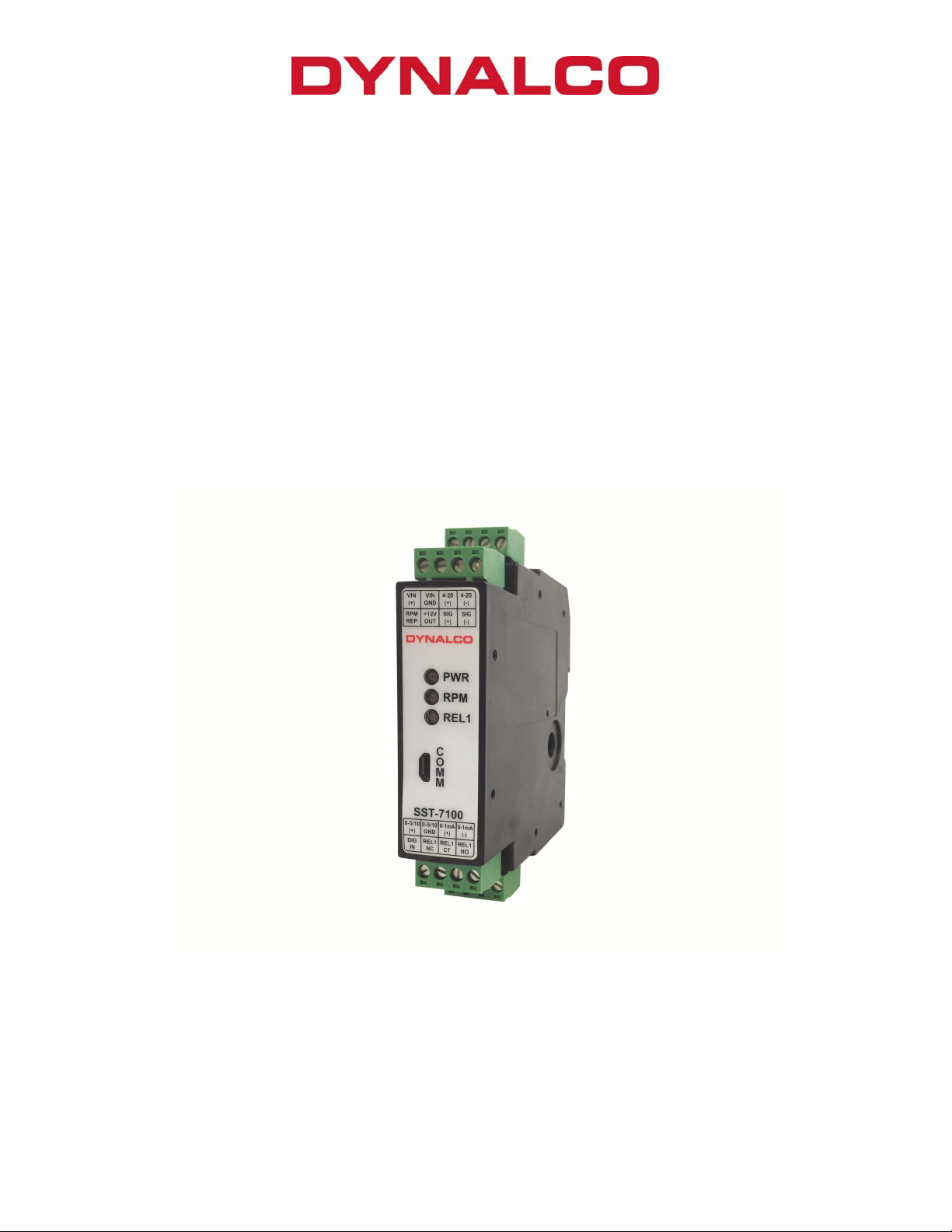
Terminal Connections
PIN
Description
PIN
Description
All connections are made via the terminal blocks on the front of the unit.
VIN
(+)
VIN
GND
4-20
(+)
4-20
(-)
RPM
REP
+12V
OUT
SIG
(+)
SIG
(-)
10 - 36 VDC Supply (+) 0-5/10
(+)
Supply Ground (-) 0-5/10
GND
4-20 mA Proportional Output (+) 0-1mA
(+)
4-20 mA Proportional Output (-) 0-1mA
(-)
Repeater Output (+)
(pulsed square wave)
DIG
IN
Power for 3-wire pickups REL1
NC
Signal Input (+) from speed
sensor
Signal Input (-) from speed
sensor
REL1
CT
REL1
NO
0-5 or 0-10 VDC Proportional
Output (+)
0-5 or 0-10 VDC Proportional
Output (-)
0-1 mA local meter output (+)
0-1 mA local meter output (-)
Digital Input for resetting latched
relay (SST7100)
Normally-Closed Relay Contact
(SST7100)
Relay Common (SST7100)
Normally-Open Relay Contact
(SST7100)
Terminal screws to be tightened to 4 inchpounds torque.
6
Page 8

Outline Dimensions
7
Page 9

Dynalco SST7000 Series Software
The Dynalco host software provides serial communication between a PC or laptop and the
SST7000 series. The software is compatible with Windows XP, Vista and Windows 7
operating systems. The SST7000 must be connected via Dynalco p/n 270A-XXXXX serial
communication cable. This cable is sold separately.
The Dynalco host software is available as a free download from our website:
www.dynalco.com/downloads
Following installation, a shortcut will be installed on your PC desktop. This application
software allows access to various screens for configuration of input signal sensitivity,
proportional output and relay logic / setpoints. Once the configuration parameters are set,
they can be programmed into the SST7000 and a spec file can be saved to the PC. This
saved spec file can then be loaded into another SST7000 if desired. Additionally, there is an
import function allowing uploading of the spec file from an SST7000 to the PC.
Configuration consists of the steps described in the following pages:
8
Page 10
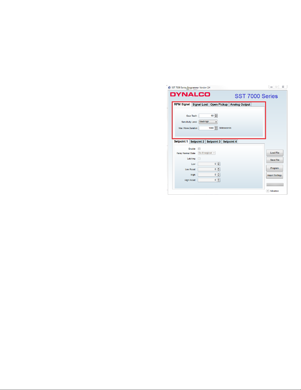
RPM Signal
The RPM Signal needs to be programmed prior to all other settings.
The SST7000 series is capable of accepting input signals from 2-wire (also known as
variable reluctance) magnetic pickups as well as 3-wire (powered, TTL or hall-effect) type
sensors. The output from 2-wire pickups is an AC signal where the 3-wire type will normally
have a positive-going (non zero-crossing) square wave output.
• Gear Teeth
o Required to convert RPM to Hz for
proper calibration
• Sensitivity Level
o Set for Med-High for most applications
o Higher sensitivity will allow greater
sensitivity if needed for low speed
applications
o Lower sensitivity will be less sensitive to
noise
• Max Wave Duration
o The Max Wave Duration is defined as the maximum time allowed between input
signal pulses before a sensor fault is declared. For example, a shaft with 2
keyways turning at 0 – 10 RPM would have an extremely low frequency range,
calibrated below:
Frequency = RPM X # teeth / 60
= 10 X 2 / 60 = 0.333 Hz
Then, the period (time in seconds between pulses) is calculated as:
Period = 1 / Frequency
= 1 / 0.333 = 3 seconds
In this example, the pulses would be received in time intervals of once every 3
seconds or longer. The Max Wave Duration can be configured to a maximum
value of 10,000 milliseconds (10 seconds) to allow for this low speed range.
Any pulse not received within 10 seconds would be considered a sensor fault.
o Note that the default value of 1000 Milliseconds (1 second) is correct for most
applications.
9
Page 11

Signal Lost (SST7100 only)
The signal lost function is defined as the absolute maximum allowable period (time between
input pulses in milliseconds) before an under speed relay is tripped. Similar to the Max Wave
Duration described in the previous step, the Signal Lost is necessary for low speed applications
where there is a programmed under speed trip. This setting should be set longer than the
period (in milliseconds) of the under speed setpoint.
• Enable
o Check this box to enable Signal Lost
o If there is no under speed setpoint, leave un-checked
• Time Out
o This is the maximum time (in milliseconds) allowed before an under speed trip
is initiated.
• Trip
o Select Setpoint 1 for the SST7100
10
Page 12
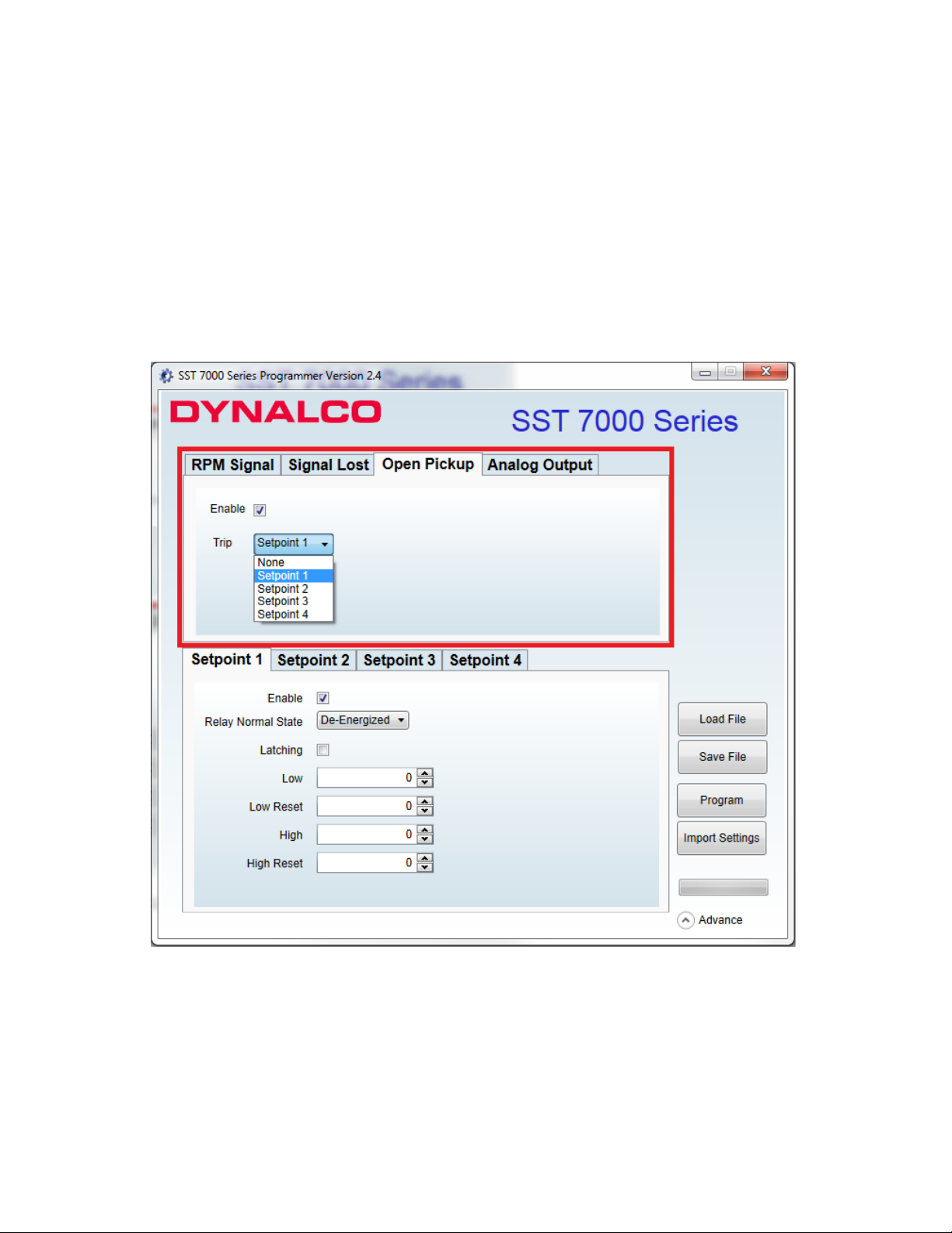
Open Pickup (SST7100 only)
The Open Pickup tab allows the user to select which relay (if any) will activate if an open
pickup is sensed.
• Enable
o Check this box to enable Open Pickup option
• Trip
o Select Setpoint 1 for the SST7100
11
Page 13

Analog Output
The analog output tab is used to define the RPM range of the proportional 4 – 20 mA output.
• RPM Zero
o Set to the RPM value corresponding to 4 mA output.
o Normally set to 0 RPM but can be set to any value as long as it is lower than
the RPM span.
• RPM Span
o Set to the RPM value corresponding to 20 mA output.
12
Page 14

Setpoint 1 (SST7100 only)
The Setpoint 1 tab allows configuration of the relay setpoint and relay logic for the single
relay on the SST7100.
• Enable
o Check this box to enable setpoint 1
• Relay Normal State
o This is the normal relay state when not tripped
o Either select normally Energized or normally De-Energized
WARNING:
For critical applications, it is highly recommended to configure the Relay Normal State as “normally
Energized.” This configuration will cause the contacts to switch in the event of a relay coil failure.
• Latching
o Un-check this box to select non-latching relay (auto-reset following trip)
o Check this box to select latching relay (must be manually reset following trip)
o A momentary contact from DIG IN (digital input) to VIN GND (supply ground)
will reset latching relay
• Low RPM
o Selects under speed setpoint
o Set to 0 if no under speed setpoint required
• High RPM
o Selects over speed setpoint
• Reset Low RPM
o Defines the reset value
following an under speed trip
o Must be set at least 1% higher
than Low RPM value to
prevent relay chatter
o Set to 0 if no under speed
setpoint required
• Reset High RPM
o Defines the reset value
following an over speed trip
o Must be set at least 1% lower
than High RPM value to
prevent relay chatter
13
Page 15

Program
Following initial configuration of the unit or any
setting changes, you will need to select
“Program” to program the new settings to the
SST7000 / SST7100.
Save File
Selecting “Save File” allows the new settings to
be saved to a file location on the PC.
14
Page 16

Load File
Any spec files that have been saved to the PC
can be loaded to the SST7000 application by
selecting “Load File.”
Following this, you will need to select “Program”
to write the new configuration to the SST7000.
Import Settings
Selection of “Import Settings” will upload the
current settings to be read by the SST7000
series software.
WARNING:
The relay output on the SST7100 should be tested monthly for proper operation,
especially if being used for engine overspeed shutdown or other critical function.
15
 Loading...