

Page 1

3690 N.W. 53rd Street
Fort Lauderdale, FL 33309
SC-2124
SC-2124M
24 Channel Universal Scanner
Installation and Operation
Manual
P/N 145F-11902
Rev. 3.30
(c) Copyright 2000, Dynalco Controls
All Rights Reserved
Published: October 6, 2000
Revised: October 21, 2009
1
Page 2

TABLE OF CONTENTS
1.0 Introduction 3
1.1 Ratings & Certification 6
2.0 Installation 7
2.1 Panel Cutout 7
2.2 Wiring 8
2.3 Mounting 10
3.0 Setup 13
3.1 HOST Software 13
3.1.1 Setup Screen 14
3.1.2 Configuration File 15
4.0 Standard Operation 16
4.1 RESET 17
4.2 START 17
4.3 ALARM 18
4.4 SHUTDOWN 18
5.0 User Interface 19
5.1 Navigation 19
5.2 Run Screens 21
5.2.1 Title Screen 21
5.2.2 Main Menu Screen 22
5.2.3 Main SCANNER Screen 22
5.2.4 SCAN Screen 23
5.2.5 Custom Screen(s) 23
5.2.6 Channel Screens 23
5.2.6.1 HELP Screens 24
5.2.7 SNAP Screen 24
5.2.7.1 First-Out Screen 24
FIGURES
Configuration Screen 14
1
2 Run Screens 20
APPENDICES
Appendix A Configuration Parameter List 25
Appendix B Example of a Configuration File 54
Appendix C Instructions for Downloading WinHost 67
Appendix D Modbus Addresses 68
Appendix E SC-RTD Module 69
2
Page 3

1.0 Introduction
The SC-2124 is a microprocessor-based universal scanner for continuous monitoring of up
to 24 channels measuring temperature from thermocouples, pressure or any other analog
signal that can be represented by either 0-5V or 4-20mA . Each scanner channel may be
configured for the following input types:
• J, K, E, or T thermocouple inputs
• 4-20 mA inputs (8 on-board resistors available via DIP switch)
• 0-5 V Inputs
The SC-2124 provides ALARM and SHUTDOWN capabilities via two dedicated on-board 5
Amp relays (plus 2 additional general-purpose relays) and automatically TRIPs should any
user-programmable threshold be exceeded.
The SC-2124 utilizes all DB-Style Connectors on the back of the unit for a cleaner wiring
arrangement. All wiring to the unit is done via separate DIN-RAIL type terminal modules and
then DB-25/15 cables connect to the unit.
The SC-2124 front panel includes a large-character, 4-row by 20-column, backlit LCD display
and application keypad. The display has several Run Screens: a SCAN Screen that displays
each enabled scanner channel, one channel screen at a time; one or more Custom Screens
to display up to four user-specified scanner channels per screen; and a SNAPSHOT Screen
that displays each enabled channel’s analog input reading at the time of the last
SHUTDOWN plus indication of the “First-Out” channel causing the shutdown.
Utilizing an on-board RS-232 communications port with a convenient DB-9 connector, the
SC-2124 provides powerful communications capabilities. Quick and easy configuration is
done from a laptop computer using the Dynalco DYNALINK software. The unit can also
switch protocols and talk Modbus RTU for continuous remote monitoring.
3
Page 4

1.1 Packaging
Front View
6.55"
8.50"
4
Page 5
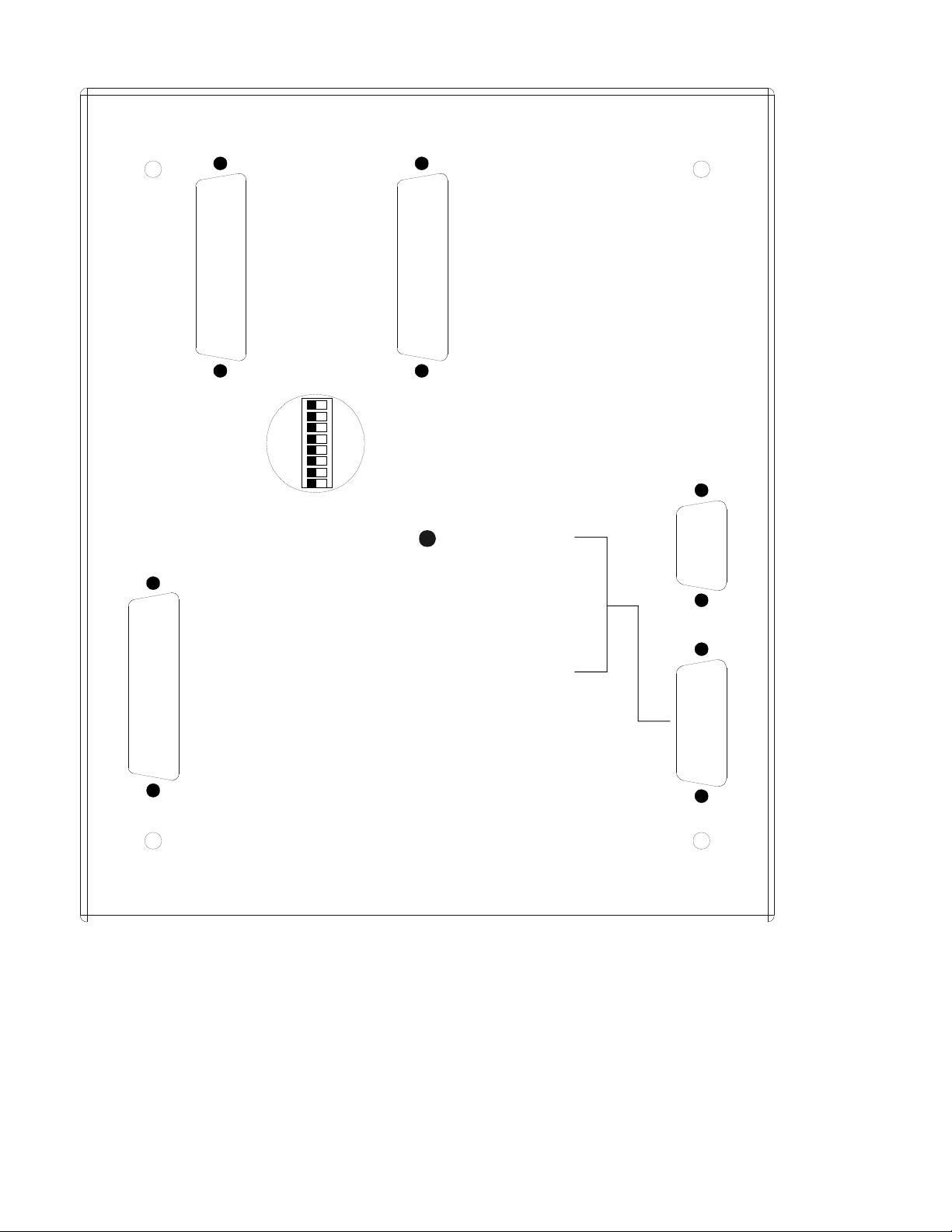
Rear View
CONN E
CHANNELS 1 - 8
4-20mA RESISTORS
CONN C
CONTACTS
(1) RLY 1 N/C
(3) RLY 1 COM.
(5) RLY 1 N/O
RELAY
ANALOG
INPUTS
13-24
OFF
CONN D
ANALOG
INPUTS
1-12
1
2
ON
3
4
5
6
7
8
DC POWER /
INSTRUMENTS
(1) CJC INPUT
(2) +5 VDC CJC POWER
(3) GND
(14) +DC POWER
(13, 15) DC POWER GND
RS232
COMMUNICATION
CONN B
CONN A
(7) RLY 2 N/C
(9) RLY 2 COM
(11) RLY 2 N/O
(15) RLY 3 N/C
(17) RLY 3 COM
(19) RLY 3 N/O
(21) RLY 4 COM
(23) RLY 4 COM
(25) RLY 4 N/O
5
Page 6

1.2 Specifications
1. Input Channels:24 Thermocouple (J,K,T, or E), 0 – 5V, or 4 – 20mA (On-Board 100
Ohm resistor provided on Channels 1 through 8).
Note: All Thermocouples have “Open-Thermocouple Detection”
2. Channel Scan Rate: Programmable (50mS Minimum)
3. Relay Outputs: 4 Relays, SPDT, rated @ 5A/24VDC, 1A/120VAC, and 0.5A/220VAC
4. Input Power: 9 – 38 VDC, 0.8A Max.
5. Sensor Power Out: +5VDC CJC Sensor Power, +8VDC RPM Sensor Power
6. Display: Backlit, 4 Line x 20 Character Alphanumeric Display with large 0.36”
Characters
7. Communications:
Hardware: RS-232
Software: Dynalink Laptop Configuration Software and Modbus RTU.
8. Rear Connections: All “DB - Style” Connectors on rear of unit. All field Wiring is done
via DIN-RAIL mounted Terminal Blocks.
9. Operating Temperature Range: -20 to +80C
10. Certification: CSA Class I, Div.2, Groups A, B, C, D
6
Page 7
2.0 Installation
Installation requires a cutout as shown in section 2.1 along with four mounting holes. Once
the unit is mounted, a nearby (less than 6 feet away) location is needed for performing the
wiring to separate terminals. One method is to purchase the optional DB-to-Screw-Terminal
modules which are DIN-RAIL mounted. Also, the supplied Cold Junction Compensation
(CJC) Sensor is necessary if any thermocouples are to be used. The Dynalco ETS-202 CJC
sensor should be mounted as close as possible to the location where the thermocouple wires
are terminated.
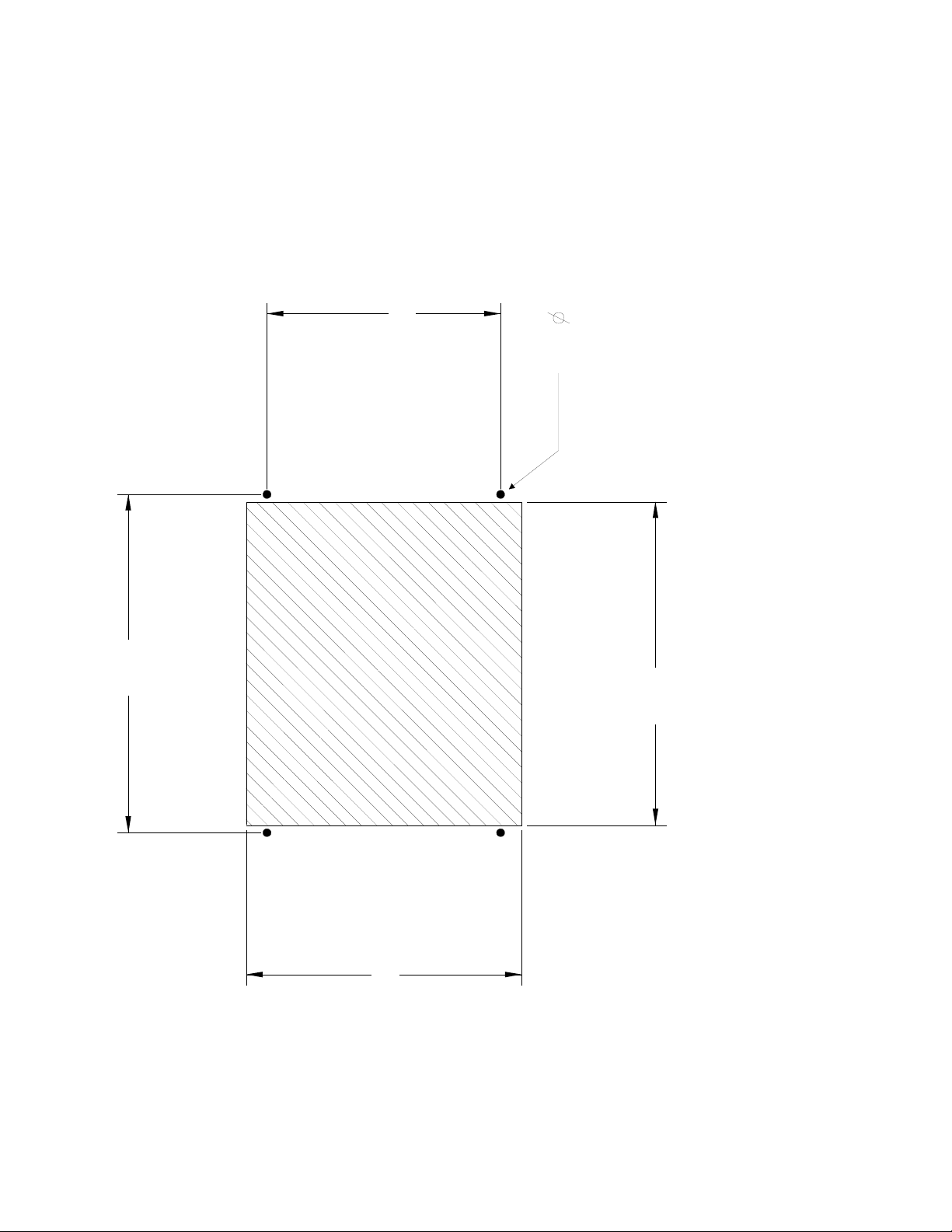
2.1 Panel Cutout
5.30
.1875
7.85
PANEL
CUTOUT
6.25
7.50
7
Page 8

2.2 Wiring
Connector A (DB-15M):
This Connector is used for the DC Power Input and the Cold Junction Compensation (CJC)
Sensor Input. In addition, depending upon the Scanner Model, it also contains Meter Bus
signals and an RPM Input.
Pinout: Pin#
Pin Name
1 CJC Sensor Input (WHT)
2 +5VDC CJC Sensor Power (RED)
3 CJC Sensor Common (BLK)
4 +8VDC RPM Sensor Power
5 RPM Input
6 RPM Common
7 NO CONNECTION
8 NO CONNECTION
9 Display (IIC Bus) Data
10 Display (IIC Bus) Clock
11 CAN Bus +
12 CAN Bus 13 Common
14 + DC Power In
15 DC Power Common
Connector B (DB-9F)
This Connector is used for RS-232 Communications to either a Laptop for Configuration or a
Modbus Communications Link.
Pinout: Pin# Pin Name
1 NO CONNECTION
2 Transmit Data Out
3 Receive Data In
4 NO CONNECTION
5 Common
6 NO CONNECTION
7 NO CONNECTION
8 NO CONNECTION
9 NO CONNECTION
8
Page 9

2.2 Wiring (Cont’d)
Connector C (DB-25M)
This Connector provides Contact Outputs for the 4 on-board relays.
Pinout: Pin# Pin Name
1 Relay 1 NC Contact
2 NO CONNECTION
3 Relay 1 Com
4 NO CONNECTION
5 Relay 1 NO Contact
6 NO CONNECTION
7 Relay 2 NC Contact
8 NO CONNECTION
9 Relay 2 Com
10 NO CONNECTION
11 Relay 2 NO Contact
12 NO CONNECTION
13 NO CONNECTION
14 NO CONNECTION
15 Relay 3 NC Contact
16 NO CONNECTION
17 Relay 3 Com
18 NO CONNECTION
19 Relay 3 NO Contact
20 NO CONNECTION
21 Relay 4 NC Contact
22 NO CONNECTION
23 Relay 4 Com
24 NO CONNECTION
25 Relay 4 NO Contact
2.2 DIP Switch (Rear of Unit)
Channels 1 – 8 have a 100 Ohm resistor available across their inputs for use with 4-20mA
inputs ONLY. Only move the appropriate DIP switch to the “ON” side if that channel is to be
configured as a 4-20mA input.
If any inputs besides channels # 1 – 8 are to be configured for 4 – 20 mA, a 100 ohm resistor
will need to be installed across the corresponding input channel terminations on the terminal
block.
NOTE: Setting the DIP switch to “ON” for either a 0-5V or thermocouple input will result in
faulty operation of the SC-2124.
9
Page 10

2.2 Wiring (Cont’d)
Connectors D and E are input terminals, each requiring p/n SC-CBLE25MM cable / terminal
block assembly.
Thermocouples can be connected to any input of either connector D or E.
For linear inputs (4 – 20 mA or 0 – 5 VDC) it is recommended to connect the wires to the
appropriate terminals for connector D. However, either connector D or E may be used. See
previous page for information on DIP switch settings for 4 – 20 mA inputs.
Any RTD inputs require the RTD module p/n SC-RTD, which includes the cable assembly. In
this case ,p/n SC-CBLE25MM will not be required. Note that (1) SC-RTD will handle up to 12
RTD inputs and can be connected to either connector D (Ch # 1 – 12) or connector E (Ch #
13 – 24).
Instructions for SC-RTD module configuration are in Appendix E.
Connector D (DB-25F)
This Connector provides the Analog Inputs for Channels 1 – 12.
Pinout:
Pin# Pin Name Pin# Pin Name
1 Channel 1 (+) 14 Channel 1 (-)
2 Channel 2 (+) 15 Channel 2 (-)
3 Channel 3 (+) 16 Channel 3 (-)
4 Channel 4 (+) 17 Channel 4 (-)
5 Channel 5 (+) 18 Channel 5 (-)
6 Channel 6 (+) 19 Channel 6 (-)
7 Channel 7 (+) 20 Channel 7 (-)
8 Channel 8 (+) 21 Channel 8 (-)
9 Channel 9 (+) 22 Channel 9 (-)
10 Channel 10 (+) 23 Channel 10 (-)
11 Channel 11 (+) 24 Channel 11 (-)
12 Channel 12 (+) 25 Channel 12 (-)
10
Page 11

Connector E (DB-25F)
This Connector provides the Analog Inputs for Channels 13 – 24.
Pinout:
Pin Name Pin# Pin Name
Pin#
1 Channel 13 (+) 14 Channel 13 (-)
2 Channel 14 (+) 15 Channel 14 (-)
3 Channel 15(+) 16 Channel 15 (-)
4 Channel 16 (+) 17 Channel 16 (-)
5 Channel 17 (+) 18 Channel 17 (-)
6 Channel 18 (+) 19 Channel 18 (-)
7 Channel 19 (+) 20 Channel 19 (-)
8 Channel 20 (+) 21 Channel 20 (-)
9 Channel 21 (+) 22 Channel 21 (-)
10 Channel 22 (+) 23 Channel 22 (-)
11 Channel 23 (+) 24 Channel 23 (-)
12 Channel 24 (+) 25 Channel 24 (-)
11
Page 12
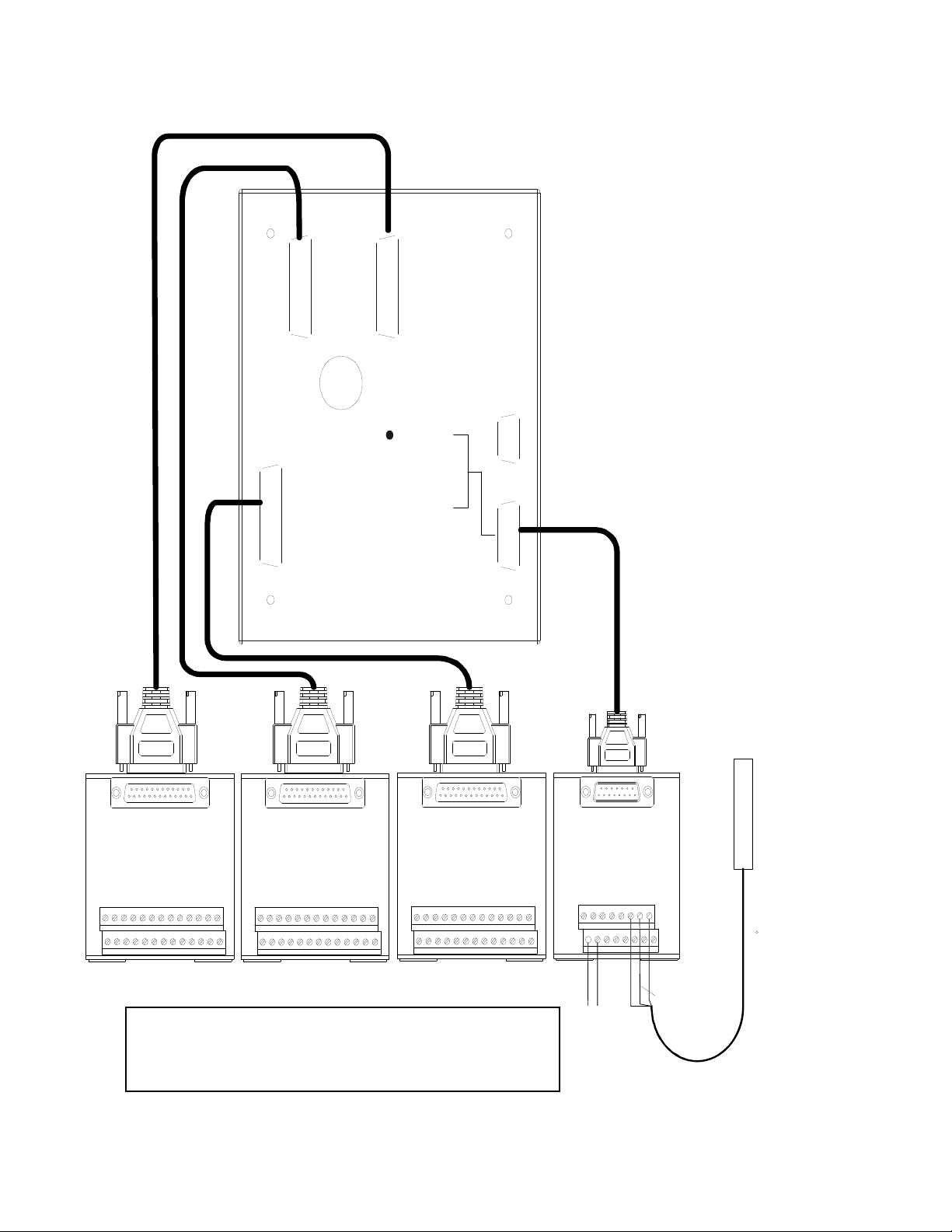
2.2 Wiring (Cont’d) Optional DB cables and
R
DB-to-Screw -Terminal DIN-RAIL Modules are available
CONN E
CONN D
ANALOG
INPUTS
13-24
ANALOG
INPUTS
1-12
4-20mA ENABLES
CHANNELS 1 - 8
OFF
ON
RS232
COMMUNICATION
CONN B
CONN C
RELAY
CONTACTS
(1) RLY 1 N/C
(3) RLY 1 COM.
(5) RLY 1 N/O
(7) RLY 2 N/C
(9) RLY 2 COM
(11) RLY 2 N/O
(15) RLY 3 N/C
(17) RLY 3 COM
(19) RLY 3 N/O
(21) RLY 4 COM
(23) RLY 4 COM
(25) RLY 4 N/O
DC POWER / CJC
(1) CJC INPUT
(2) +5 VDC CJC POWE
(3) GND
(14) +DC POWER
(13, 15) DC POWER GND
CONN A
(ANALOG INPUTS 13-24)
Note that terminal blocks for connectors A, C, D & E may
be different than illustration above, although terminal
designations on pages 8 – 11 are correct.
CJC
SENSOR
(ETS-202)
CONN ACONN CCONN E CONN D
(DC POWER/ CJC) (RELAYS)(ANALOG INPUTS 1-12)
12
Page 13

3.0 Setup
The SC-2124 requires the user to configure a variety of parameters: SCANNER channel
analog inputs; ALARM & SHUTDOWN TRIP conditions; Main SCAN Screen; and other
various other parameters. These parameters must be configured through the use of Dynalco
Controls HOST software. The user configures SCANNER parameters by either a useredited download file or individual parameter modification. The following sections details use
of the HOST software, download file, and parameter modification.
3.1 HOST Software
Dynalco Controls HOST software provides serial communication between a PC or laptop and
the SC-2124. WinHost is compatible with Windows 95, 98, 2000 & XP operating systems.
When communicating via WinHost software, the SCANNER must be connected via a
standard RS-232, 9-pin, male-female, serial communication cable. The HOST software
communicates to the SCANNER via Dynalink, Dynalco Control’s serial communication
protocol.
Each parameter has its own parameter number as listed in the spec file example in
Appendix B
When you open WinHost, you should see current parameters in the monitor screens. If you
see "??" instead of parameter values, check the serial link cable.
Any parameter value can be read by entering the parameter # in the "Command" line located
in the lower left corner of the monitor screen in WinHost. For example if you want to know
the value of parameter # 8001.1 (input type for channel 1) you would type 8001.1 in the
command line and hit enter. You will see the value of that parameter in the "Response" line
which is below the command line.
If you want to change the value of parameter 8001.1 so that channel 1 would be configured
for a K type thermocouple, you would then type in 8001.1=1 in the command line. After
hitting enter, you should see an "@" sign in the response line, indicating that the new value
was accepted.
Remember to always click on "Store" at the top of the screen after making changes.
Otherwise, the new values will be lost if you lose power to the SC2124.
In order to save any changes made to the scanner, you must store the new parameters as
follows:
Enter a letter "S" in the command line after making the changes. The response should be the
usual "@" sign.
During the store process, the SC2124 display will indicate "Configuration Parameter Store In
Progress." Make sure that the power is not removed during the "store" operation or you will
lose the saved data and all parameters will return to default values.
See Appendix B for instructions on downloading and installing WinHost software.
13
Page 14

3.1.1 Setup Screen
The SCANNER has the capability of communicating via Dynalink (point to point) using the
communications cable p/n CBLE-8509 or via Modbus (SC2124M only) through the serial
communications port CONN B. The user must setup the SCANNER to communicate via
Dynalink in order to configure the SCANNER with HOST software. A Configuration Screen
is available to switch between the Dynalink and Modbus protocols (See Figure 1).
Figure 1, Configuration Screen
COMMUNICATION
SETUP SCREEN
0
SELECT COMM PROTOCOL
>DYNALINK< MODBUS
D D M M
To enter Configuration Mode, the user must press the SETUP Key. The Communication
Setup Screen prompts the user to select a communication protocol. To communicate with
Dynalco Controls HOST software, the user must select the Dynalink protocol. To
communicate with an external device on a Modbus, the user must select the Modbus
protocol. To select either protocol, the user must press either of the Soft Keys located under
the corresponding protocol listed in the last row of the Configuration Screen. The currently
selected protocol is enclosed in brackets (‘>’ and ‘<’). The default SCANNER protocol is
Dynalink.
To exit Configuration Mode, the user must press and hold the ESC Key for one second.
14
Page 15

3.1.2 Configuration File
The easiest method for the user to configure the SC-2124 is by editing and downloading a
configuration file to the SCANNER. The configuration file is a template file that contains all
configurable parameters and an explanation for all parameter configuration settings. The
user must enter desired configuration values for all appropriate configuration parameters
before downloading the file to the SCANNER.
The configuration file can be edited with any text editor or word processor that can save files
in text format, such as Notepad or Wordpad available on Windows PCs.
The download file contains configuration comments and parameter configurations. The
comments for the configuration parameters explain the function for each parameter and the
programmable values associated for each parameter. The comments are any text or text
characters that follow a semicolon. General SCANNER configuration comments should not
be deleted. However, some comments, such as ‘<ANALOG INPUT CHANNEL #01>’, have
been included for the user to overwrite with application-specific descriptors, such as ‘Engine
Exhaust Temperature’.
The configuration file’s parameter configurations program the corresponding SC-2124
parameters when the file is downloaded to the SCANNER.
See Appendix A for an example of the standard SC2124.spc configuration file.
15
Page 16

4.0 Standard Operation
After power-up, the SC-2124 performs all standard SCANNER operations continually. These
operations include scanning all enabled analog input channels to update the channel
readings; monitoring channel inputs for Open Thermocouple, ALARM, or SHUTDOWN TRIP
conditions; performing Dynalink or Modbus communications to external devices.
To update all scanner channels, the SCANNER reads all enabled channels’ current analog
input readings. These readings are performed continuously and sequentially for all enabled
scanner channels. Current channel measurement readings are averaged with the previous
value to update the current analog input channel value.
The SCANNER then monitors each channel’s value compared to the channel’s configured
ALARM and SHUTDOWN thresholds. If any of the channel thresholds is exceeded, the
channels are considered to be in a fault state, and the SCANNER TRIPs an ALARM or
SHUTDOWN (See Sections 4.3 & 4.4). In addition, the SCANNER monitors all
thermocouple channels for Open Thermocouple detection. If any thermocouple channel is
open, the SCANNER labels that channel as open and displays ‘OPEN TC’ instead of that
channel’s current analog input reading. Detection of an open thermocouple on any scanner
channel may also result in an ALARM or SHUTDOWN (See Sections 4.3, 4.4, & 3.1.2.1).
Lastly, the SCANNER continually communicates with any external devices that initiate
communication and request SCANNER parameters. The SCANNER is capable of
communicating by Dynalink and Modbus. Only one serial communication port is available on
the SC-2124; thus, only one type of communication may occur on the port at any one time
(See Section 3.1). Dynalink would be used primarily while the SCANNER is being
configured using Dynalco Controls HOST software. Modbus communication would be used
to connect the SCANNER to other devices that communicate via Modbus.
16
Page 17

4.1 RESET
After power-up, the SC-2124 starts up in a RESET condition that assumes that all channels
are in a non-fault state, initializes the ALARM and SHUTDOWN TRIP conditions to a nonfault state, and forces all relays and discrete outputs to their non-fault states. After startup,
however, the user must manually RESET any TRIP conditions by a RESET key press from
the front panel or by setting the RESET parameter via HOST software (See Section 3.2.3).
This forces the user to actively acknowledge every SCANNER ALARM and SHUTDOWN.
When a RESET is manually triggered, the SCANNER clears the ALARM and SHUTDOWN
TRIP conditions and forces all relays and discrete outputs to their non-fault states. The
RESET is performed even if any scanner channels are in a fault state. If this is the case, the
SCANNER immediately TRIPs a new ALARM or SHUTDOWN (See Sections 4.3 & 4.4).
4.2 START
After RESET, the user may trigger specific SCANNER monitoring conditions via a START
request. To trigger a START request, the user must press the START key from the front
panel or set the START parameter via HOST software (See Section 3.2.3).
When a START is triggered, the SCANNER reloads the TRIP Class B timer with its initial
timer value, expressed in minutes. Once loaded, the timer ticks down until it expires,
whereupon all TRIP Class B channels become active. If any Class B channel is in a fault
state, no ALARM or SHUTDOWN is TRIPPED until the Class B timer is expired.
17
Page 18

4.3 ALARM
The SCANNER provides a precautionary ALARM warning to alert the user to potentially
hazardous or dangerous input conditions. The SCANNER monitors all enabled scanner
channels’ current analog input readings and compares each channel’s reading with a userconfigurable ALARM threshold. If any channel’s ALARM threshold is exceeded, the
SCANNER TRIPs an ALARM condition and blinks the ALARM indicator LED on the front
panel. A SCANNER ALARM is not latched and clears if no channel’s ALARM threshold is
faulted.
4.4 SHUTDOWN
The SCANNER provides a protective SHUTDOWN fault to guard against hazardous or
dangerous fault conditions. The SCANNER monitors all enabled scanner channels’ current
analog input readings and compares each channel’s reading with a user-configurable
SHUTDOWN threshold. If any channel’s SHUTDOWN threshold is exceeded, the
SCANNER TRIPs a SHUTDOWN condition and blinks the SHUTDOWN indicator LED on
the front panel.
When a SHUTDOWN occurs, the SCANNER saves the channel that caused the
SHUTDOWN to non-volatile memory as the First-Out channel. This First-Out channel is the
first channel that the SCANNER detects in a SHUTDOWN fault state. The SCANNER
displays the First-Out cause of the SHUTDOWN on the Main SCANNER Screen (See
Section 5.2.3). A SCANNER SHUTDOWN is latched and is not cancelled until
acknowledged by a RESET (See Section 4.1).
At the time of a SHUTDOWN, other scanner channels may be in a SHUTDOWN fault state.
Since several channels may be faulted, it is possible that another scanner channel besides
the First-Out channel caused the actual SHUTDOWN—the SCANNER merely detected and
labeled one faulted channel before the actual First-Out channel.
To aid the user in analyzing a SCANNER SHUTDOWN, the SCANNER also takes a Snap
Shot of all enabled scanner channels’ analog input readings at the time of the SHUTDOWN
and saves these Snap Shots to non-volatile memory. These Snap Shot values are displayed
on the SNAP Screen (See Section 5.2.7) and may be viewed after the user acknowledges
the SHUTDOWN condition via a SCANNER RESET. Only one set of SHUTDOWN Snap
Shot values is saved to memory at any one time. When a subsequent SHUTDOWN occurs,
the new Snap Shot values overwrite the old values in memory.
18
Page 19

5.0 User Interface
The SC-2124 user interface located on the front panel of the SCANNER consists of a largecharacter, 4-row by 20-column, backlit LCD display and an application keypad. The LCD
display is used to display SCANNER channel readings, SHUTDOWN First-Outs,
SHUTDOWN Snap Shot histories, and other informative statistics.
5.1 Navigation
The application keypad is used to navigate between Run Screens that display various
SCANNER readings and statistics. The keypad has the following keys used for navigation:
• UP, DOWN, LEFT, RIGHT Keys Navigate to screen in the desired direction
• Soft Keys Located directly under the LCD display,
these keys navigate to various screens as
indicated in the last line of the LCD display
• RESET Key RESET SCANNER
• START Key START SCANNER timers
• Setup Key Enter Configuration Mode
• ESC Key Navigate up one menu level; exit from
Configuration Mode
In addition to navigation, the user may execute specific key-press events from certain
screens. These screen-specific functions are typically labeled above corresponding Soft
Keys. To execute any screen-specific event function, the user must press and release the
corresponding Soft Key located below the labeled function. To repeatedly execute some
event functions, the user must press and hold the corresponding Soft Key. All SC-2124
screen-specific functions are described in the following sections that detail screen operation.
19
Page 20
Figure 2, Run Screens
120 10
110 10
SCN CH02 PIST 1 PRES
In: 738 PSI
SCN CH01 ENG TEMP
In: 1452 °F
Th: 750 PSI
Th: 1800 °F
SNAP
150 +
HELP NEXT
125 10
FIRST-OUT SCREEN
SCN CH03 PIST 2 PRES
In: 755 PSI
Th: 750 PSI
FIRST-OUT SNAP
First Out Shutdown Channel on
SNAP Screen & First-Out Screen
will blink 'FIRST-OUT' in lower
left-hand corner of screen
110 10
SCN CH02 PIST 1 PRES
In: 689 PSI
Th: 750 PSI
150 +
HELP NEXT
110 10
SCN CH24
In: DISABLED
Th: 0 °F
150 +
HELP NEXT
SCAN-2 124 R u n Scr ee ns
TITLE SCREEN
0 10
DYNALCO CONTROLS
SCAN-2124
- +
V1.00
10 0
MAIN MENU SCREEN
MAIN
SCAN CUSTOM CH SNAP
200 10
ENG TEMP 1452
PIST 1 PRES 689
PIST 2 PRES 697
200 10
SCN Ch #05 1201
SCN Ch #06 1189
SCN Ch #09 DISABLED
HELP SCREENS
150 110
SCN CH02 PIST 1 PRES
Connector: CONN 4
SCAN SCREEN CUSTOM SCREEN(S) CHANNEL SCREENS SNAP SCREEN
100 200 110 120
100 10
SCN CH01 ENG TEMP
In: 1452 °F
10 200 110 120
Th: 1800 °F
MAIN CUSTOM CH SNAP
2nd Custom Screen
If available
110 +
+ Pin : PIN 02
- Pin : PIN 15
20
Page 21

5.2 Run Screens
The main purpose of the SC-2124 Run Screens is to allow the user to navigate to and from
screens that display current run-time values of scanner channels. Several screens are
available to display channel information in a few different formats (See Figure 1).
Each screen is shown with the following information: screen ID, screen text display,
navigational links, and possible screen event functions. This information is listed both in the
large, main text box area of the screen, as well as in the smaller informational boxes above
and below the main text box.
Listed in the upper, left-hand box is each screen’s navigational ID. Listed inside the main text
box is each screen’s text and run-time values display. Listed in the upper, right-hand box is
the navigational link to the next screen if the user presses the ESC Key. Listed in the boxes
below the main text box are the navigational links to other Run Screens or possible event
functions if the user presses any Soft Keys. If a navigational ID is listed, then the user
navigates to the specified screen if the user presses corresponding Soft Key. If a function is
listed by a ‘+’ or ‘-‘, then the user executes a screen-specific event function if the user
presses the corresponding Soft Key (See Section 5.1).
The following sections describe the behavior and functions available for each of the Run
Screens.
5.2.1 Title Screen
At startup, the SC-2124 displays the SCANNER Title Screen that includes the Dynalco
Controls banner, SCANNER name, and software version number. This Title Screen is
displayed for five seconds before navigating to the user-configured SCANNER Screen (See
Section 5.2.3).
In addition to the above information, this screen has two Soft Keys that increase or decrease
the LCD contrast. The left-most Soft Key decreases the LCD contrast by one step for every
key press or by one step every 200 milliseconds if the key is held. The right-most Soft Key
increases the LCD contrast by one step for every key press or by one step every 200
milliseconds if the key is held. The five second display timer is reset if any user key presses
are detected. This allows the user enough time to adjust the LCD contrast. If the user
modifies the LCD contrast, the SCANNER performs a CONFIGURATION Store to nonvolatile memory at screen exit to save the contrast setting.
21
Page 22

After startup, the user may navigate to the Title Screen from the Main Menu Screen. This
allows the user to adjust the LCD contrast at any time during the operation of the SC-2124.
The Title Screen is displayed for five seconds before navigating back to the Main Menu
Screen. The user may immediately navigate back to the Main Menu Screen by pressing the
ESC Key at any time.
5.2.2 Main Menu Screen
The Main Menu Screen allows fast navigation to all other Run Screens. To navigate to a
particular Run Screen, the user must press the Soft Key located directly under the
corresponding Screen Name listed on the Main Menu Screen: SCAN, Custom, Channel, or
SNAP. The user may also navigate to the Title Screen by pressing the ESC Key.
5.2.3 Main SCANNER Screen
One of the SC-2124 Run Screens is user-configured as the Main SCANNER Screen. This is
the main screen where the user views and monitors most of the information displayed by the
SCANNER. By default, the SCAN Screen is configured as the SCANNER Screen, but the
user may also configure the Custom Screen(s) as the SCANNER Screen.
For either configuration, the SCANNER Screen displays current measurement readings of
the analog input channels during normal operation. When a SHUTDOWN occurs, the
SCANNER automatically navigates† back to the Main SCANNER Screen to display the FirstOut SHUTDOWN channel, i.e. the cause of the SHUTDOWN (See Section 4.4). No
navigation may be performed until the First-Out SHUTDOWN is acknowledged by a
SCANNER RESET (See Section 4.1).
Since the Main SCANNER Screen is the default screen of primary interest to the user, the
SCANNER automatically navigates† back to the Main SCANNER Screen after 60 seconds of
user inactivity (delay is user-configurable).
†
Note: The SCANNER performs the automatic navigation only if the SC-2124
is in RUN Mode Screens, not in CONFIGURATION Mode. This allows the
user to enter CONFIGURATION Mode during a SHUTDOWN to modify
parameters that may cancel the SHUTDOWN condition.
22
Page 23

5.2.4 SCAN Screen
The SCAN Screen is the default SCANNER screen. The SCAN Screen displays each
enabled scanner channel for three seconds (delay is user-configurable) before displaying the
next enabled channel. Each channel display includes channel number, name, current
analog input reading (with units), and SHUTDOWN TRIP threshold (with units). If no
scanner channels are enabled, the SCAN Screen displays ‘ALL CHANNELS DISABLED’.
The SCAN Screen also contains fast navigation links back to the Main Menu Screen, as well
as to the Custom, Channel, and SNAP Screens. As from the Main Menu, to navigate to a
particular Run Screen, the user must press the Soft Key located directly under the
corresponding Screen Name listed in the last row of the SCAN Screen. In addition to the
fast navigational link, the user may also navigate back to the Main Menu by pressing the
ESC Key.
5.2.5 Custom Screen(s)
The Custom Screen(s) are user-configurable screens that display up to four scanner
channels per custom screen. The user may configure up to eight total scanner channels to
be displayed on two custom screens. If both custom screens are active, each custom screen
displays its configured scanner channels for three seconds (delay is user-configurable)
before displaying the next custom screen. If no custom screens are active, the Custom
Screen displays ‘NO CUSTOM SCREENS AVAILABLE’.
A custom screen is active if at least one scanner channel is configured to display on the
screen. Each scanner channel is displayed on its own row. If a user-configured channel
name is available, this channel name is displayed on the left-hand portion of the row.
Otherwise, the channel number is displayed on the left-hand portion of the row. The
channel’s current analog input reading is displayed on the right-hand portion of the row. If
the channel is disabled, the right-hand portion of the row displays ‘DISABLED’ instead of the
current analog input reading.
To navigate back to the Main Menu, the user must press the ESC Key.
5.2.6 Channel Screens
The Channel Screens display individual scanner channels. The display of each scanner
channel is identical to the format described for the SCAN Screen. Each channel displays
channel number, name, current analog input reading (with units), and SHUTDOWN TRIP
threshold (with units). Unlike the SCAN Screen, the SCANNER displays the individual
scanner channel without automatically displaying the next scanner channel after three
seconds. Note that the SCANNER returns to the Main SCANNER Screen after 60 seconds
of user inactivity (See Section 5.2.3).
To display the next scanner channel, the user must press the right-most Soft Key, labeled
‘NEXT’. In addition, the user may press the DOWN Key to display the next scanner channel
or the UP Key to display the previous scanner channel. To navigate back to the Main Menu,
the user must press the ESC Key.
23
Page 24

5.2.6.1 HELP Screens
In addition to viewing the channel’s current analog input reading, the Channel Screen
provides a link to channel HELP Screens. Each HELP Screen informs the user of the
specific Din Rail Connector and Pin-out for any scanner channel. To view the HELP Screen,
the user must press the left-most Soft Key, labeled ‘HELP’. This navigates to the desired
HELP Screen that displays the Connector number and +/- Pin Input numbers for the specific
scanner channel.
To return to the Channel Screen, the user must press either the ESC Key or the left-most
Soft Key. To view the next scanner channel’s HELP Screen, the user must press either the
right-most Soft Key or the DOWN Key, and to view the previous scanner channel’s HELP
Screen, the user must press the UP Key. To navigate back to the Main Menu, the user must
press the ESC Key.
5.2.7 SNAP Screen
The SNAP Screen displays a Snap Shot of all enabled scanner channels’ analog input
readings at the time of the last SHUTDOWN. The display of each scanner channel Snap
Shot is identical to the format described for the SCAN Screen. Each channel displays
channel number, name, Snap Shot analog input reading (with units), and SHUTDOWN TRIP
threshold (with units). To inform the user that the display values are a Snap Shot of the last
SHUTDOWN, the SNAP Screen displays ‘SNAP’ in the lower, right-hand corner of the
screen. In addition, to indicate the First-Out channel that caused the last SHUTDOWN (See
Section 4.4), the SNAP Screen blinks ‘FIRST-OUT’ in the lower, left-hand corner of the
screen whenever the First-Out channel is displayed.
Note that the values displayed are those saved from each channel’s analog input reading
and configuration at the time of the last SHUTDOWN. If any channel’s configuration
parameters have been modified since the last SHUTDOWN, it follows that these values will
differ from the current configuration settings.
To navigate to the First-Out Screen to display the First-Out channel, the user may press
either the UP or DOWN Key. To navigate back to the SNAP Screen, the user must again
press either the UP or DOWN Key. To navigate back to the Main Menu, the user must press
the ESC Key.
5.2.7.1 First-Out Screen
The First-Out Screen displays the First-Out channel that caused the last SHUTDOWN (See
Section 4.4). The display of the First-Out channel is identical to the format described for the
SCAN Screen. The First-Out Screen displays First-Out channel number, name, Snap Shot
analog input reading (with units), and SHUTDOWN TRIP threshold (with units). To indicate
to the user that the display value is the First-Out channel, the First-Out Screen blinks ‘FIRSTOUT’ in the lower, left-hand corner of the screen and displays ‘SNAP’ in the lower, right-hand
corner of the screen.
To navigate to the SNAP Screen, the user may press either the UP or DOWN Key. To
navigate back to the First-Out Screen, the user must again press either the UP or DOWN
Key. To navigate back to the Main Menu, the user must press the ESC Key.
24
Page 25

V
,
Appendix A
This appendix contains a table of all parameter numbers found in the
SCAN2124.SPC file.
Use this appendix to keep track of the values you assign to each parameter number. The
numbers in this table are in the same order as they appear in the SCAN2124.SPC file.
Password Settings
Parameter
6130=
6101= Change the time that the Configuration Password is active Minimum= 30 seconds
Description
Changes the Configuration Password
AFTER the user exits Configuration Mode Default= 60 seconds
alid Inputs
Default=1234
"8 characters of'1'
Maximum=540 seconds
Trip Relay Settings
Parameter Description Valid Inputs
136=
63102.1= Sets trip action for user relay 1.
63102.2= Sets trip action for user relay 2.
63102.3= Sets trip action for alarm relay.
63102.4= Sets trip action for shutdown relay.
149= Selects trip action for any open thermocouple
63050= Changes the Trip Class B timer triggered from
144= Changes the Trip Class B timer time remaining
Configure relays as inverted outputs or non-inverted
outputs
channel
front-panel 'Start' key press
before Class B faults are displayed
0= relay outputs non-inverted
1= relay outputs inverted (default)
0= normally energized
1= normally de-energized
2= normally energized latching
3= normally de-energized latching
0= disabled (default)
1= alarm
2= shutdown
0= 0 minutes
1=1 minute (default)
2= 2 minutes
3= 3 minutes
4= 4 minutes
5= 5 minutes
0= 0 seconds
1=15 seconds
2=30 seconds (default)
3=45 seconds
4=60 seconds
5=75 seconds
6=90 seconds
'2','3', or '4'"
25
Page 26

Scan Screen Settings
Parameter Description Valid Inputs
195= Selects type of scan screen to view (default or 0= displays default screen (enabled channels
custom) shown one at a time)
1= displays custom screen (shows up to 4
140= Define time between scan screens Minimum= 2 seconds
141= Change the time it takes to return to the main 0= off
scanner screen after no key press activity 1= 1 minute (default)
170= Select the scanner channel or node to display 0= display scanner channel number [‘CHXX’]
Custom Screen Settings
Parameter Defines the analog input channel to display on: Valid Input:
190.1= Screen 1, Line 1 0 = off (default)
190.2= Screen 1, Line 2
190.3= Screen 1, Line 3
190.4= S creen 1, Line 4
190.5= Screen 2, L ine 1
190.6= S creen 2, Line 2
190.7= Screen 2, Line 3
190.8= S creen 2, Line 4
190.9= Screen 3, L ine 1
190.10= Scr e en 3, Lin e 2
190.11= Screen 3, Line 3
190.12= Scr e en 3, Lin e 4
190.13= Scree n 4, Line 1
190.14= Scr e en 4, Lin e 2
190.15= Screen 4, Line 3
190.16= Scr e en 4, Lin e 4
190.17= Scree n 5, Line 1
190.18= Scr e en 5, Lin e 2
190.19= Screen 5, Line 3
190.20= Scr e en 5, Lin e 4
190.21= Screen 6, Line 1
190.22= Scr e en 6, Lin e 2
190.23= Screen 6, Line 3
190.24= Screen 6, Line 4
channels on one screen)
Default= 3 seconds
Maximum=10 seconds
2= 2 minutes 3= 3
minutes 4= 4
m i n u t es 5= 5
minutes
(default)
1= display scanner node number [‘N:XX’]
1 to 24= analog input channel
26
Page 27

Channel 1 Input Settings
Parameter Function Description Valid Inputs
110.1= Channel name for CH01
111.1= Units of measure for CH01
8001.1= Input type for CH01
8000.1= Enables CH01 for scanning
8017.1= Filter speed for CH01
8012.1= Display value for 0 V or 4 mA input Minimum=-999.0
8013.1= Display value for 5 V or 20 mA input
8015.1= Inverted resistance for 4-20mA source on CH01
8008.1= CH01 output offset to add to computed output value
63000.1= Shutdown trip class for CH01
63001.1= Shutdown threshold value for CH01 Numeric value
63002.1= Shutdown threshold hystersis for CH01
63003.1=
63000.25= Alarm trip class for CH01
63001.25= Alarm threshold value for CH01 Numeric value
63002.25= Alarm threshold hysteresis for CH01
63003.25=
Delay time between exceeded CH01 shutdown threshold and
CH01 shutdown
Delay time between exceeded CH01 alarm threshold and
CH01 alarm
Default=” “ (blank=CH01)
11 characters (including spaces)
0= deg F (default)
1= deg C
2= PSI
3= PSA
4= KPA
5= FTP
6= RPM
7= “ “ (blank)
0= J-TC (default)
1= K-TC
2= Nickel RTD
3= Platinum RTD
4= 4-20 mA (DIP 1 switch on)
5= 0-5 V
0= disabled (default)
1= enabled
Minimum=0.00 (none)
Default=0.05 (slow)
Maximum=1.00 (fast)
Default= 0.0
Maximum=9999.0
(in channel units)
Minimum=0.0 1/kohms
Default=10.0 1/kohms
Maximum=100.0 1 /kohms
Minimum=-1000.0
Default= 0.0
Maximum= 1000.0
(in channel units)
0= Off
1= Class A over (default)
2= Class B over
3= Class C over
4= Class A under
5= Class B under
6= Class C under
(channel units)
seconds
0= Off
1= Class A over (default)
2= Class B over
3= Class C over
4= Class A under
5= Class B under
6= Class C under
(channel units)
seconds
27
Page 28

Channel 2 Input Settings
Parameter Function Description Valid Inputs
110.2= Channel name for CH02
111.2= Units of measure for CH02
8001.2= Input type for CH02
8000.2= Enables CH02 for scanning
8017.2= Filter speed for CH02
8012.2= Display value for 0 V or 4 mA input Minimum=-999.0
8013.2= Display value for 5 V or 20 mA input
8015.2= Inverted resistance for 4-20mA source on CH02
8008.2= CH02 output offset to add to computed output value
63000.2= Shutdown trip class for CH02
63001.2= Shutdown threshold value for CH02 Numeric value
63002.2= Shutdown threshold hystersis for CH02
63003.2=
63000.26= Alarm trip class for CH02
63001.26= Alarm threshold value for CH02 Numeric value
63002.26= Alarm threshold hysteresis for CH02
63003.26=
Delay time between exceeded CH02 shutdown threshold and
CH02 shutdown
Delay time between exceeded CH02 alarm threshold and
CH02 alarm
Default=” “ (blank=CH02)
11 characters (including spaces)
0= deg F (default)
1= deg C
2= PSI
3= PSA
4= KPA
5= FTP
6= RPM
7= “ “ (blank)
0= J-TC (default)
1= K-TC
2= Nickel RTD
3= Platinum RTD
4= 4-20 mA (DIP 2 switch on)
5= 0-5 V
0= disabled (default)
1= enabled
Minimum=0.00 (none)
Default=0.05 (slow)
Maximum=1.00 (fast)
Default= 0.0
Maximum=9999.0
(in channel units)
Minimum=0.0 1/kohms
Default=10.0 1/kohms
Maximum=100.0 1 /kohms
Minimum=-1000.0
Default= 0.0
Maximum= 1000.0
(in channel units)
0= Off
1= Class A over (default)
2= Class B over
3= Class C over
4= Class A under
5= Class B under
6= Class C under
(channel units)
seconds
0= Off
1= Class A over (default)
2= Class B over
3= Class C over
4= Class A under
5= Class B under
6= Class C under
(channel units)
seconds
28
Page 29

Appendix C
Channel 3 Input Settings
Parameter Function Description Valid Inputs
110.3= Channel name for CH03
111.3= Units of measure for CH03
8001.3= Input type for CH03
8000.3= Enables CH03 for scanning
8017.3= Filter speed for CH03
8012.3= Display value for 0 V or 4 mA input Minimum=-999.0
8013.3= Display value for 5 V or 20 mA input
8015.3= Inverted resistance for 4-20mA source on CH03
8008.3= CH03 output offset to add to computed output value
63000.3= Shutdown trip class for CH03
63001.3= Shutdown threshold value for CH03
63002.3= Shutdown threshold hystersis for CH03
63003.3=
63000.27 Alarm trip class for CH03
63001.27= Alarm threshold value for CH03
63002.27= Alarm threshold hysteresis for CH03
63003.27=
Delay time between exceeded CH03 shutdown threshold and
CH03 shutdown
Delay time between exceeded CH03 alarm threshold and
CH03 alarm
Default=” “ (blank=CH03)
11 characters (including spaces)
0= deg F (default)
1= deg C
2= PSI
3= PSA
4= KPA
5= FTP
6= RPM
7= “ “ (blank)
0= J-TC (default)
1= K-TC
2= Nickel RTD
3= Platinum RTD
4= 4-20 mA (DIP 3 switch on)
5= 0-5 V
0= disabled (default)
1= enabled
Minimum=0.00 (none)
Default=0.05 (slow)
Maximum=1.00 (fast)
Default= 0.0
Maximum=9999.0
(in channel units)
Minimum=0.0 1/kohms
Default=10.0 1/kohms
Maximum=100.0 1 /kohms
Minimum=-1000.0
Default= 0.0
Maximum= 1000.0
(in channel units)
0= Off
1= Class A over (default)
2= Class B over
3= Class C over
4= Class A under
5= Class B under
6= Class C under
Numeric value
(channel units)
seconds
0= Off
1= Class A over (default)
2= Class B over
3= Class C over
4= Class A under
5= Class B under
6= Class C under
Numeric value
(channel units)
seconds
29
Page 30

Channel 4 Input Settings
Parameter Function Description Valid Inputs
110.4= Channel name for CH04
111.4= Units of measure for CH04
8001.4= Input type for CH04
8000.4= Enables CH04 for scanning
8017.4= Filter speed for CH04
8012.4= Display value for 0 V or 4 mA input Minimum=-999.0
8013.4= Display value for 5 V or 20 mA input
8015.4= Inverted resistance for 4-20mA source on CH04
8008.4= CH04 output offset to add to computed output value
63000.4= Shutdown trip class for CH04
63001.4= Shutdown threshold value for CH04 Numeric value
63002.4= Shutdown threshold hystersis for CH04
63003.4=
63000.28= Alarm trip class for CH04
63001.28= Alarm threshold value for CH04 Numeric value
63002.28= Alarm threshold hysteresis for CH04
63003.28=
Delay time between exceeded CH04 shutdown threshold and
CH04 shutdown
Delay time between exceeded CH04 alarm threshold and
CH04 alarm
Default=” “ (blank=CH04)
11 characters (including spaces)
0= deg F (default)
1= deg C
2= PSI
3= PSA
4= KPA
5= FTP
6= RPM
7= “ “ (blank)
0= J-TC (default)
1= K-TC
2= Nickel RTD
3= Platinum RTD
4= 4-20 mA (DIP 4 switch on)
5= 0-5 V
0= disabled (default)
1= enabled
Minimum=0.00 (none)
Default=0.05 (slow)
Maximum=1.00 (fast)
Default= 0.0
Maximum=9999.0
(in channel units)
Minimum=0.0 1/kohms
Default=10.0 1/kohms
Maximum=100.0 1 /kohms
Minimum=-1000.0
Default= 0.0
Maximum= 1000.0
(in channel units)
0= Off
1= Class A over (default)
2= Class B over
3= Class C over
4= Class A under
5= Class B under
6= Class C under
(channel units)
seconds
0= Off
1= Class A over (default)
2= Class B over
3= Class C over
4= Class A under
5= Class B under
6= Class C under
(channel units)
seconds
30
Page 31

Appendix C
Channel 5 Input Settings
Parameter Function Description Valid Inputs
110.5= Channel name for CH05
111.5= Units of measure for CH05
8001.5= Input type for CH05
8000.5= Enables CH05 for scanning
8017.5= Filter speed for CH05
8012.5= Display value for 0 V or 4 mA input Minimum=-999.0
8013.5= Display value for 5 V or 20 mA input
8015.5= Inverted resistance for 4-20mA source on CH05
8008.5= CH05 output offset to add to computed output value
63000.5= Shutdown trip class for CH05
63001.5= Shutdown threshold value for CH05 Numeric value
63002.5= Shutdown threshold hystersis for CH05
63003.5=
63000.29= Alarm trip class for CH05
63001.29= Alarm threshold value for CH05 Numeric value
63002.29= Alarm threshold hysteresis for CH05
63003.29=
Delay time between exceeded CH05 shutdown threshold and
CH05 shutdown
Delay time between exceeded CH05 alarm threshold and
CH05 alarm
Default=” “ (blank=CH05)
11 characters (including spaces)
0= deg F (default)
1= deg C
2= PSI
3= PSA
4= KPA
5= FTP
6= RPM
7= “ “ (blank)
0= J-TC (default)
1= K-TC
2= Nickel RTD
3= Platinum RTD
4= 4-20 mA (DIP 5 switch on)
5= 0-5 V
0= disabled (default)
1= enabled
Minimum=0.00 (none)
Default=0.05 (slow)
Maximum=1.00 (fast)
Default= 0.0
Maximum=9999.0
(in channel units)
Minimum=0.0 1/kohms
Default=10.0 1/kohms
Maximum=100.0 1 /kohms
Minimum=-1000.0
Default= 0.0
Maximum= 1000.0
(in channel units)
0= Off
1= Class A over (default)
2= Class B over
3= Class C over
4= Class A under
5= Class B under
6= Class C under
(channel units)
seconds
0= Off
1= Class A over (default)
2= Class B over
3= Class C over
4= Class A under
5= Class B under
6= Class C under
(channel units)
seconds
31
Page 32

Channel 6 Input Settings
Parameter Function Description Valid Inputs
110.6= Channel name for CH06
111.6= Units of measure for CH06
8001.6= Input type for CH06
8000.6= Enables CH06 for scanning
8017.6= Filter speed for CH06
8012.6= Display value for 0 V or 4 mA input Minimum=-999.0
8013.6= Display value for 5 V or 20 mA input
8015.6= Inverted resistance for 4-20mA source on CH06
8008.6= CH06 output offset to add to computed output value
63000.6= Shutdown trip class for CH06
63001.6= Shutdown threshold value for CH06 Numeric value
63002.6= Shutdown threshold hystersis for CH06
63003.6=
63000.30= Alarm trip class for CH06
63001.30= Alarm threshold value for CH06 Numeric value
63002.30= Alarm threshold hysteresis for CH06
63003.30=
Delay time between exceeded CH06 shutdown threshold and
CH06 shutdown
Delay time between exceeded CH06 alarm threshold and
CH06 alarm
Default=” “ (blank=CH06)
11 characters (including spaces)
0= deg F (default)
1= deg C
2= PSI
3= PSA
4= KPA
5= FTP
6= RPM
7= “ “ (blank)
0= J-TC (default)
1= K-TC
2= Nickel RTD
3= Platinum RTD
4= 4-20 mA (DIP 6 switch on)
5= 0-5 V
0= disabled (default)
1= enabled
Minimum=0.00 (none)
Default=0.05 (slow)
Maximum=1.00 (fast)
Default= 0.0
Maximum=9999.0
(in channel units)
Minimum=0.0 1/kohms
Default=10.0 1/kohms
Maximum=100.0 1 /kohms
Minimum=-1000.0
Default= 0.0
Maximum= 1000.0
(in channel units)
0= Off
1= Class A over (default)
2= Class B over
3= Class C over
4= Class A under
5= Class B under
6= Class C under
(channel units)
seconds
0= Off
1= Class A over (default)
2= Class B over
3= Class C over
4= Class A under
5= Class B under
6= Class C under
(channel units)
seconds
32
Page 33

Appendix C
Channel 7 Input Settings
Parameter Function Description Valid Inputs
110.7= Channel name for CH07
111.7= Units of measure for CH07
8001.7= Input type for CH07
8000.7= Enables CH07 for scanning
8017.7= Filter speed for CH07
8012.7= Display value for 0 V or 4 mA input Minimum=-999.0
8013.7= Display value for 5 V or 20 mA input
8015.7= Inverted resistance for 4-20mA source on CH07
8008.7= CH07 output offset to add to computed output value
63000.7= Shutdown trip class for CH07
63001.7= Shutdown threshold value for CH07 Numeric value
63002.7= Shutdown threshold hystersis for CH07
63003.7=
63000.31= Alarm trip class for CH07
63001.31= Alarm threshold value for CH07 Numeric value
63002.31= Alarm threshold hysteresis for CH07
63003.31=
Delay time between exceeded CH07 shutdown threshold and
CH07 shutdown
Delay time between exceeded CH07 alarm threshold and
CH07 alarm
Default=” “ (blank=CH07)
11 characters (including spaces)
0= deg F (default)
1= deg C
2= PSI
3= PSA
4= KPA
5= FTP
6= RPM
7= “ “ (blank)
0= J-TC (default)
1= K-TC
2= Nickel RTD
3= Platinum RTD
4= 4-20 mA (DIP 7 switch on))
5= 0-5 V
0= disabled (default)
1= enabled
Minimum=0.00 (none)
Default=0.05 (slow)
Maximum=1.00 (fast)
Default= 0.0
Maximum=9999.0
(in channel units)
Minimum=0.0 1/kohms
Default=10.0 1/kohms
Maximum=100.0 1 /kohms
Minimum=-1000.0
Default= 0.0
Maximum= 1000.0
(in channel units)
0= Off
1= Class A over (default)
2= Class B over
3= Class C over
4= Class A under
5= Class B under
6= Class C under
(channel units)
seconds
0= Off
1= Class A over (default)
2= Class B over
3= Class C over
4= Class A under
5= Class B under
6= Class C under
(channel units)
seconds
33
Page 34

Channel 8 Input Settings
Parameter Function Description Valid Inputs
110.8= Channel name for CH08
111.8= Units of measure for CH08
8001.8= Input type for CH08
8000.8= Enables CH08 for scanning
8017.8= Filter speed for CH08
8012.8= Display value for 0 V or 4 mA input Minimum=-999.0
8013.8= Display value for 5 V or 20 mA input
8015.8= Inverted resistance for 4-20mA source on CH08
8008.8= CH08 output offset to add to computed output value
63000.8= Shutdown trip class for CH08
63001.8= Shutdown threshold value for CH08 Numeric value
63002.8= Shutdown threshold hystersis for CH08
63003.8=
63000.32= Alarm trip class for CH08
63001.32= Alarm threshold value for CH08 Numeric value
63002.32= Alarm threshold hysteresis for CH08
63003.32=
Delay time between exceeded CH08 shutdown threshold and
CH08 shutdown
Delay time between exceeded CH08 alarm threshold and
CH08 alarm
Default=” “ (blank=CH08)
11 characters (including spaces)
0= deg F (default)
1= deg C
2= PSI
3= PSA
4= KPA
5= FTP
6= RPM
7= “ “ (blank)
0= J-TC (default)
1= K-TC
2= Nickel RTD
3= Platinum RTD
4= 4-20 mA (DIP 8 switch on)
5= 0-5 V
0= disabled (default)
1= enabled
Minimum=0.00 (none)
Default=0.05 (slow)
Maximum=1.00 (fast)
Default= 0.0
Maximum=9999.0
(in channel units)
Minimum=0.0 1/kohms
Default=10.0 1/kohms
Maximum=100.0 1 /kohms
Minimum=-1000.0
Default= 0.0
Maximum= 1000.0
(in channel units)
0= Off
1= Class A over (default)
2= Class B over
3= Class C over
4= Class A under
5= Class B under
6= Class C under
(channel units)
seconds
0= Off
1= Class A over (default)
2= Class B over
3= Class C over
4= Class A under
5= Class B under
6= Class C under
(channel units)
seconds
34
Page 35

Appendix C
Channel 9 Input Settings
Parameter Function Description Valid Inputs
110.9= Channel name for CH09
111.9= Units of measure for CH09
8001.9= Input type for CH09
8000.9= Enables CH09 for scanning
8017.9= Filter speed for CH09
8012.9= Display value for 0 V or 4 mA input Minimum=-999.0
8013.9= Display value for 5 V or 20 mA input
8015.9= Inverted resistance for 4-20mA source on CH09
8008.9= CH09 output offset to add to computed output value
63000.9= Shutdown trip class for CH09
63001.9= Shutdown threshold value for CH09 Numeric value
63002.9= Shutdown threshold hystersis for CH09
63003.9=
63000.33= Alarm trip class for CH09
63001.33= Alarm threshold value for CH09 Numeric value
63002.33= Alarm threshold hysteresis for CH09
63003.33=
Delay time between exceeded CH09 shutdown threshold and
CH09 shutdown
Delay time between exceeded CH09 alarm threshold and
CH09 alarm
Default=” “ (blank=CH09)
11 characters (including spaces)
0= deg F (default)
1= deg C
2= PSI
3= PSA
4= KPA
5= FTP
6= RPM
7= “ “ (blank)
0= J-TC (default)
1= K-TC
2= Nickel RTD
3= Platinum RTD
4= 4-20 mA (ext. resistor req’d)
5= 0-5 V
0= disabled (default)
1= enabled
Minimum=0.00 (none)
Default=0.05 (slow)
Maximum=1.00 (fast)
Default= 0.0
Maximum=9999.0
(in channel units)
Minimum=0.0 1/kohms
Default=10.0 1/kohms
Maximum=100.0 1 /kohms
Minimum=-1000.0
Default= 0.0
Maximum= 1000.0
(in channel units)
0= Off
1= Class A over (default)
2= Class B over
3= Class C over
4= Class A under
5= Class B under
6= Class C under
(channel units)
seconds
0= Off
1= Class A over (default)
2= Class B over
3= Class C over
4= Class A under
5= Class B under
6= Class C under
(channel units)
seconds
35
Page 36

Channel 10 Input Settings
Parameter Function Description Valid Inputs
110.10= Channel name for CH10
111.10= Units of measure for CH10
8001.10= Input type for CH10
8000.10= Enables CH10 for scanning
8017.10= Filter speed for CH10
8012.10= Display value for 0 V or 4 mA input Minimum=-999.0
8013.10= Display value for 5 V or 20 mA input
8015.10= Inverted resistance for 4-20mA source on CH10
8008.10= CH10 output offset to add to computed output value
63000.10= Shutdown trip class for CH10
63001.10= Shutdown threshold value for CH10 Numeric value
63002.10= Shutdown threshold hystersis for CH10
63003.10=
63000.34= Alarm trip class for CH10
63001.34= Alarm threshold value for CH10 Numeric value
63002.34= Alarm threshold hysteresis for CH10
63003.34=
Delay time between exceeded CH10 shutdown threshold and
CH10 shutdown
Delay time between exceeded CH10 alarm threshold and
CH10 alarm
Default=” “ (blank=CH10)
11 characters (including spaces)
0= deg F (default)
1= deg C
2= PSI
3= PSA
4= KPA
5= FTP
6= RPM
7= “ “ (blank)
0= J-TC (default)
1= K-TC
2= Nickel RTD
3= Platinum RTD
4= 4-20 mA (ext. resistor req’d)
5= 0-5 V
0= disabled (default)
1= enabled
Minimum=0.00 (none)
Default=0.05 (slow)
Maximum=1.00 (fast)
Default= 0.0
Maximum=9999.0
(in channel units)
Minimum=0.0 1/kohms
Default=10.0 1/kohms
Maximum=100.0 1 /kohms
Minimum=-1000.0
Default= 0.0
Maximum= 1000.0
(in channel units)
0= Off
1= Class A over (default)
2= Class B over
3= Class C over
4= Class A under
5= Class B under
6= Class C under
(channel units)
seconds
0= Off
1= Class A over (default)
2= Class B over
3= Class C over
4= Class A under
5= Class B under
6= Class C under
(channel units)
seconds
36
Page 37

Appendix C
Channel 11 Input Settings
Parameter Function Description Valid Inputs
110.11= Channel name for CH 11
111.11= Units of measure for CH11
8001.11= Input type for CH11
8000.11= Enables CH11 for scanning
8017.11= Filter speed for CH11
8012.11= Display value for 0 V or 4 mA input Minimum=-999.0
8013.11= Display value for 5 V or 20 mA input
8015.11= Inverted resistance for 4-20mA source on CH11
8008.11= CH11 output offset to add to computed output value
63000.11= Shutdown trip class for CH11
63001.11= Shutdown threshold value for CH11 Numeric value
63002.11= Shutdown threshold hystersis for CH11
63003.11=
63000.35= Alarm trip class for CH11
63001.35= Alarm threshold value for CH11 Numeric value
63002.35= Alarm threshold hysteresis for CH11
63003.35=
Delay time between exceeded CH11 shutdown threshold and
CH11 shutdown
Delay time between exceeded CH11 alarm threshold and
CH11 alarm
Default=” “ (blank=CH11)
11 characters (including spaces)
0= deg F (default)
1= deg C
2= PSI
3= PSA
4= KPA
5= FTP
6= RPM
7= “ “ (blank)
0= J-TC (default)
1= K-TC
2= Nickel RTD
3= Platinum RTD
4= 4-20 mA (ext. resistor req’d)
5= 0-5 V
0= disabled (default)
1= enabled
Minimum=0.00 (none)
Default=0.05 (slow)
Maximum=1.00 (fast)
Default= 0.0
Maximum=9999.0
(in channel units)
Minimum=0.0 1/kohms
Default=10.0 1/kohms
Maximum=100.0 1 /kohms
Minimum=-1000.0
Default= 0.0
Maximum= 1000.0
(in channel units)
0= Off
1= Class A over (default)
2= Class B over
3= Class C over
4= Class A under
5= Class B under
6= Class C under
(channel units)
seconds
0= Off
1= Class A over (default)
2= Class B over
3= Class C over
4= Class A under
5= Class B under
6= Class C under
(channel units)
seconds
37
Page 38

Channel 12 Input Settings
Parameter Function Description Valid Inputs
110.12= Channel name for CH12
111.12= Units of measure for CH12
8001.12= Input type for CH12
8000.12= Enables CH12 for scanning
8017.12= Filter speed for CH12
8012.12= Display value for 0 V or 4 mA input Minimum=-999.0
8013.12= Display value for 5 V or 20 mA input
8015.12= Inverted resistance for 4-20mA source on CH12
8008.12= CH12 output offset to add to computed output value
63000.12= Shutdown trip class for CH12
63001.12= Shutdown threshold value for CH12 Numeric value
63002.12= Shutdown threshold hystersis for CH12
63003.12=
63000.36= Alarm trip class for CH12
63001.36= Alarm threshold value for CH12 Numeric value
63002.36= Alarm threshold hysteresis for CH12
63003.36=
Delay time between exceeded CH12 shutdown threshold and
CH12shutdown
Delay time between exceeded CH12 alarm threshold and
CH12 alarm
Default=” “ (blank=CH12)
11 characters (including spaces)
0= deg F (default)
1= deg C
2= PSI
3= PSA
4= KPA
5= FTP
6= RPM
7= “ “ (blank)
0= J-TC (default)
1= K-TC
2= Nickel RTD
3= Platinum RTD
4= 4-20 mA (ext. resistor req’d)
5= 0-5 V
0= disabled (default)
1= enabled
Minimum=0.00 (none)
Default=0.05 (slow)
Maximum=1.00 (fast)
Default= 0.0
Maximum=9999.0
(in channel units)
Minimum=0.0 1/kohms
Default=10.0 1/kohms
Maximum=100.0 1 /kohms
Minimum=-1000.0
Default= 0.0
Maximum= 1000.0
(in channel units)
0= Off
1= Class A over (default)
2= Class B over
3= Class C over
4= Class A under
5= Class B under
6= Class C under
(channel units)
seconds
0= Off
1= Class A over (default)
2= Class B over
3= Class C over
4= Class A under
5= Class B under
6= Class C under
(channel units)
seconds
38
Page 39

Appendix C
Channel 13 Input Settings
Parameter Function Description Valid Inputs
110.13= Channel name for CH13
111.13= Units of measure for CH13
8001.13= Input type for CH13
8000.13= Enables CH13 for scanning
8017.13= Filter speed for CH13
8012.13= Display value for 0 V or 4 mA input Minimum=-999.0
8013.13= Display value for 5 V or 20 mA input
8015.13= Inverted resistance for 4-20mA source on CH13
8008.13= CH13 output offset to add to computed output value
63000.13= Shutdown trip class for CH13
63001.13= Shutdown threshold value for CH13 Numeric value
63002.13= Shutdown threshold hystersis for CH13
63003.13=
63000.37= Alarm trip class for CH13
63001.37= Alarm threshold value for CH13 Numeric value
63002.37= Alarm threshold hysteresis for CH13
63003.37=
Delay time between exceeded CH13 shutdown threshold and
CH13shutdown
Delay time between exceeded CH13 alarm threshold and
CH13 alarm
Default=” “ (blank=CH13)
11 characters (including spaces)
0= deg F (default)
1= deg C
2= PSI
3= PSA
4= KPA
5= FTP
6= RPM
7= “ “ (blank)
0= J-TC (default)
1= K-TC
2= Nickel RTD
3= Platinum RTD
4= 4-20 mA (ext. resistor req’d)
5= 0-5 V
0= disabled (default)
1= enabled
Minimum=0.00 (none)
Default=0.05 (slow)
Maximum=1.00 (fast)
Default= 0.0
Maximum=9999.0
(in channel units)
Minimum=0.0 1/kohms
Default=10.0 1/kohms
Maximum=100.0 1 /kohms
Minimum=-1000.0
Default= 0.0
Maximum= 1000.0
(in channel units)
0= Off
1= Class A over (default)
2= Class B over
3= Class C over
4= Class A under
5= Class B under
6= Class C under
(channel units)
seconds
0= Off
1= Class A over (default)
2= Class B over
3= Class C over
4= Class A under
5= Class B under
6= Class C under
(channel units)
seconds
39
Page 40

Channel 14 Input Settings
Parameter Function Description Valid Inputs
110.14= Channel name for CH14
111.14= Units of measure for CH14
8001.14= Input type for CH14
8000.14= Enables CH14 for scanning
8017.14= Filter speed for CH14
8012.14= Display value for 0 V or 4 mA input Minimum=-999.0
8013.14= Display value for 5 V or 20 mA input
8015.14= Inverted resistance for 4-20mA source on CH14
8008.14= CH14 output offset to add to computed output value
63000.14= Shutdown trip class for CH14
63001.14= Shutdown threshold value for CH14 Numeric value
63002.14= Shutdown threshold hystersis for CH14
63003.14=
63000.38= Alarm trip class for CH14
63001.38= Alarm threshold value for CH14 Numeric value
63002.38= Alarm threshold hysteresis for CH14
63003.38=
Delay time between exceeded CH14 shutdown threshold and
CH14shutdown
Delay time between exceeded CH14 alarm threshold and
CH14 alarm
Default=” “ (blank=CH14)
11 characters (including spaces)
0= deg F (default)
1= deg C
2= PSI
3= PSA
4= KPA
5= FTP
6= RPM
7= “ “ (blank)
0= J-TC (default)
1= K-TC
2= Nickel RTD
3= Platinum RTD
4= 4-20 mA (ext. resistor req’d)
5= 0-5 V
0= disabled (default)
1= enabled
Minimum=0.00 (none)
Default=0.05 (slow)
Maximum=1.00 (fast)
Default= 0.0
Maximum=9999.0
(in channel units)
Minimum=0.0 1/kohms
Default=10.0 1/kohms
Maximum=100.0 1 /kohms
Minimum=-1000.0
Default= 0.0
Maximum= 1000.0
(in channel units)
0= Off
1= Class A over (default)
2= Class B over
3= Class C over
4= Class A under
5= Class B under
6= Class C under
(channel units)
seconds
0= Off
1= Class A over (default)
2= Class B over
3= Class C over
4= Class A under
5= Class B under
6= Class C under
(channel units)
seconds
40
Page 41

Appendix C
Channel 15 Input Settings
Parameter Function Description Valid Inputs
110.15= Channel name for CH15
111.15= Units of measure for CH15
8001.15= Input type for CH15
8000.15= Enables CH15 for scanning
8017.15= Filter speed for CH15
8012.15= Display value for 0 V or 4 mA input Minimum=-999.0
8013.15= Display value for 5 V or 20 mA input
8015.15= Inverted resistance for 4-20mA source on CH15
8008.15= CH15 output offset to add to computed output value
63000.15= Shutdown trip class for CH15
63001.15= Shutdown threshold value for CH15 Numeric value
63002.15= Shutdown threshold hystersis for CH15
63003.15=
63000.38= Alarm trip class for CH15
63001.38= Alarm threshold value for CH15 Numeric value
63002.38= Alarm threshold hysteresis for CH15
63003.38=
Delay time between exceeded CH15 shutdown threshold and
CH15shutdown
Delay time between exceeded CH15 alarm threshold and
CH15 alarm
Default=” “ (blank=CH15)
11 characters (including spaces)
0= deg F (default)
1= deg C
2= PSI
3= PSA
4= KPA
5= FTP
6= RPM
7= “ “ (blank)
0= J-TC (default)
1= K-TC
2= Nickel RTD
3= Platinum RTD
4= 4-20 mA (ext. resistor req’d)
5= 0-5 V
0= disabled (default)
1= enabled
Minimum=0.00 (none)
Default=0.05 (slow)
Maximum=1.00 (fast)
Default= 0.0
Maximum=9999.0
(in channel units)
Minimum=0.0 1/kohms
Default=10.0 1/kohms
Maximum=100.0 1 /kohms
Minimum=-1000.0
Default= 0.0
Maximum= 1000.0
(in channel units)
0= Off
1= Class A over (default)
2= Class B over
3= Class C over
4= Class A under
5= Class B under
6= Class C under
(channel units)
seconds
0= Off
1= Class A over (default)
2= Class B over
3= Class C over
4= Class A under
5= Class B under
6= Class C under
(channel units)
seconds
41
Page 42

Channel 16 Input Settings
Parameter Function Description Valid Inputs
110.16= Channel name for CH16
111.16= Units of measure for CH16
8001.16= Input type for CH16
8000.16= Enables CH16 for scanning
8017.16= Filter speed for CH16
8012.16= Display value for 0 V or 4 mA input Minimum=-999.0
8013.16= Display value for 5 V or 20 mA input
8015.16= Inverted resistance for 4-20mA source on CH16
8008.16= CH16 output offset to add to computed output value
63000.16= Shutdown trip class for CH16
63001.16= Shutdown threshold value for CH16 Numeric value
63002.16= Shutdown threshold hystersis for CH16
63003.16=
63000.40= Alarm trip class for CH16
63001.40= Alarm threshold value for CH16 Numeric value
63002.40= Alarm threshold hysteresis for CH16
63003.40=
Delay time between exceeded CH16 shutdown threshold and
CH16shutdown
Delay time between exceeded CH16 alarm threshold and
CH16 alarm
Default=” “ (blank=CH16)
11 characters (including spaces)
0= deg F (default)
1= deg C
2= PSI
3= PSA
4= KPA
5= FTP
6= RPM
7= “ “ (blank)
0= J-TC (default)
1= K-TC
2= Nickel RTD
3= Platinum RTD
4= 4-20 mA (ext. resistor req’d)
5= 0-5 V
0= disabled (default)
1= enabled
Minimum=0.00 (none)
Default=0.05 (slow)
Maximum=1.00 (fast)
Default= 0.0
Maximum=9999.0
(in channel units)
Minimum=0.0 1/kohms
Default=10.0 1/kohms
Maximum=100.0 1 /kohms
Minimum=-1000.0
Default= 0.0
Maximum= 1000.0
(in channel units)
0= Off
1= Class A over (default)
2= Class B over
3= Class C over
4= Class A under
5= Class B under
6= Class C under
(channel units)
seconds
0= Off
1= Class A over (default)
2= Class B over
3= Class C over
4= Class A under
5= Class B under
6= Class C under
(channel units)
seconds
42
Page 43

Appendix C
Channel 17 Input Settings
Parameter Function Description Valid Inputs
110.17= Channel name for CH17
111.17= Units of measure for CH17
8001.17= Input type for CH17
8000.17= Enables CH17 for scanning
8017.17= Filter speed for CH17
8012.17= Display value for 0 V or 4 mA input Minimum=-999.0
8013.17= Display value for 5 V or 20 mA input
8015.17= Inverted resistance for 4-20mA source on CH17
8008.17= CH17 output offset to add to computed output value
63000.17= Shutdown trip class for CH17
63001.17= Shutdown threshold value for CH17 Numeric value
63002.17= Shutdown threshold hystersis for CH17
63003.17=
63000.41= Alarm trip class for CH17
63001.41= Alarm threshold value for CH17 Numeric value
63002.41= Alarm threshold hysteresis for CH17
63003.41=
Delay time between exceeded CH17 shutdown threshold and
CH17shutdown
Delay time between exceeded CH17 alarm threshold and
CH17 alarm
Default=” “ (blank=CH17)
11 characters (including spaces)
0= deg F (default)
1= deg C
2= PSI
3= PSA
4= KPA
5= FTP
6= RPM
7= “ “ (blank)
0= J-TC (default)
1= K-TC
2= Nickel RTD
3= Platinum RTD
4= 4-20 mA (ext. resistor req’d)
5= 0-5 V
0= disabled (default)
1= enabled
Minimum=0.00 (none)
Default=0.05 (slow)
Maximum=1.00 (fast)
Default= 0.0
Maximum=9999.0
(in channel units)
Minimum=0.0 1/kohms
Default=10.0 1/kohms
Maximum=100.0 1 /kohms
Minimum=-1000.0
Default= 0.0
Maximum= 1000.0
(in channel units)
0= Off
1= Class A over (default)
2= Class B over
3= Class C over
4= Class A under
5= Class B under
6= Class C under
(channel units)
seconds
0= Off
1= Class A over (default)
2= Class B over
3= Class C over
4= Class A under
5= Class B under
6= Class C under
(channel units)
seconds
43
Page 44

Channel 18 Input Settings
Parameter Function Description Valid Inputs
110.18= Channel name for CH18
111.18= Units of measure for CH18
8001.18= Input type for CH18
8000.18= Enables CH18 for scanning
8017.18= Filter speed for CH18
8012.18= Display value for 0 V or 4 mA input Minimum=-999.0
8013.18= Display value for 5 V or 20 mA input
8015.18= Inverted resistance for 4-20mA source on CH18
8008.18= CH18 output offset to add to computed output value
63000.18= Shutdown trip class for CH18
63001.18= Shutdown threshold value for CH18 Numeric value
63002.18= Shutdown threshold hystersis for CH18
63003.18=
63000.42= Alarm trip class for CH18
63001.42= Alarm threshold value for CH18 Numeric value
63002.42= Alarm threshold hysteresis for CH18
63003.42=
Delay time between exceeded CH18 shutdown threshold and
CH18shutdown
Delay time between exceeded CH18 alarm threshold and
CH18 alarm
Default=” “ (blank=CH18)
11 characters (including spaces)
0= deg F (default)
1= deg C
2= PSI
3= PSA
4= KPA
5= FTP
6= RPM
7= “ “ (blank)
0= J-TC (default)
1= K-TC
2= Nickel RTD
3= Platinum RTD
4= 4-20 mA (ext. resistor req’d)
5= 0-5 V
0= disabled (default)
1= enabled
Minimum=0.00 (none)
Default=0.05 (slow)
Maximum=1.00 (fast)
Default= 0.0
Maximum=9999.0
(in channel units)
Minimum=0.0 1/kohms
Default=10.0 1/kohms
Maximum=100.0 1 /kohms
Minimum=-1000.0
Default= 0.0
Maximum= 1000.0
(in channel units)
0= Off
1= Class A over (default)
2= Class B over
3= Class C over
4= Class A under
5= Class B under
6= Class C under
(channel units)
seconds
0= Off
1= Class A over (default)
2= Class B over
3= Class C over
4= Class A under
5= Class B under
6= Class C under
(channel units)
seconds
44
Page 45

Appendix C
Channel 19 Input Settings
Parameter Function Description Valid Inputs
110.19= Channel name for CH19
111.19= Units of measure for CH19
8001.19= Input type for CH19
8000.19= Enables CH19 for scanning
8017.19= Filter speed for CH19
8012.19= Display value for 0 V or 4 mA input Minimum=-999.0
8013.19= Display value for 5 V or 20 mA input
8015.19= Inverted resistance for 4-20mA source on CH19
8008.19= CH19 output offset to add to computed output value
63000.19= Shutdown trip class for CH19
63001.19= Shutdown threshold value for CH19 Numeric value
63002.19= Shutdown threshold hystersis for CH19
63003.19=
63000.43= Alarm trip class for CH19
63001.43= Alarm threshold value for CH19 Numeric value
63002.43= Alarm threshold hysteresis for CH19
63003.43=
Delay time between exceeded CH19 shutdown threshold and
CH19shutdown
Delay time between exceeded CH19 alarm threshold and
CH19 alarm
Default=” “ (blank=CH19)
11 characters (including spaces)
0= deg F (default)
1= deg C
2= PSI
3= PSA
4= KPA
5= FTP
6= RPM
7= “ “ (blank)
0= J-TC (default)
1= K-TC
2= Nickel RTD
3= Platinum RTD
4= 4-20 mA (ext. resistor req’d)
5= 0-5 V
0= disabled (default)
1= enabled
Minimum=0.00 (none)
Default=0.05 (slow)
Maximum=1.00 (fast)
Default= 0.0
Maximum=9999.0
(in channel units)
Minimum=0.0 1/kohms
Default=10.0 1/kohms
Maximum=100.0 1 /kohms
Minimum=-1000.0
Default= 0.0
Maximum= 1000.0
(in channel units)
0= Off
1= Class A over (default)
2= Class B over
3= Class C over
4= Class A under
5= Class B under
6= Class C under
(channel units)
seconds
0= Off
1= Class A over (default)
2= Class B over
3= Class C over
4= Class A under
5= Class B under
6= Class C under
(channel units)
seconds
45
Page 46

Channel 20 Input Settings
Parameter Function Description Valid Inputs
110.20= Channel name for CH20
111.20= Units of measure for CH20
8001.20= Input type for CH20
8000.20= Enables CH20 for scanning
8017.20= Filter speed for CH20
8012.20= Display value for 0 V or 4 mA input Minimum=-999.0
8013.20= Output value for 5 V or 20 mA input
8015.20= Inverted resistance for 4-20mA source on CH20
8008.20= CH20 output offset to add to computed output value
63000.20= Shutdown trip class for CH20
63001.20= Shutdown threshold value for CH20 Numeric value
63002.20= Shutdown threshold hystersis for CH20
63003.20=
63000.44= Alarm trip class for CH20
63001.44= Alarm threshold value for CH20 Numeric value
63002.44= Alarm threshold hysteresis for CH20
63003.44=
Delay time between exceeded CH20 shutdown threshold and
CH20shutdown
Delay time between exceeded CH20 alarm threshold and
CH20 alarm
Default=” “ (blank=CH20)
11 characters (including spaces)
0= deg F (default)
1= deg C
2= PSI
3= PSA
4= KPA
5= FTP
6= RPM
7= “ “ (blank)
0= J-TC (default)
1= K-TC
2= Nickel RTD
3= Platinum RTD
4= 4-20 mA (ext. resistor req’d)
5= 0-5 V
0= disabled (default)
1= enabled
Minimum=0.00 (none)
Default=0.05 (slow)
Maximum=1.00 (fast)
Default= 0.0
Maximum=9999.0
(in channel units)
Minimum=0.0 1/kohms
Default=10.0 1/kohms
Maximum=100.0 1 /kohms
Minimum=-1000.0
Default= 0.0
Maximum= 1000.0
(in channel units)
0= Off
1= Class A over (default)
2= Class B over
3= Class C over
4= Class A under
5= Class B under
6= Class C under
(channel units)
seconds
0= Off
1= Class A over (default)
2= Class B over
3= Class C over
4= Class A under
5= Class B under
6= Class C under
(channel units)
seconds
46
Page 47

Appendix C
Channel 21 Input Settings
Parameter Function Description Valid Inputs
110.21= Channel name for CH21
111.21= Units of measure for CH21
8001.21= Input type for CH21
8000.21= Enables CH21 for scanning
8017.21= Filter speed for CH21
8012.21= Output value for 0 V or 4 mA input Minimum=-999.0
8013.21= Output value for 5 V or 20 mA input
8015.21= Inverted resistance for 4-20mA source on CH21
8008.21= CH21 output offset to add to computed output value
63000.21= Shutdown trip class for CH21
63001.21= Shutdown threshold value for CH21 Numeric value
63002.21= Shutdown threshold hystersis for CH21
63003.21=
63000.45= Alarm trip class for CH21
63001.45= Alarm threshold value for CH21 Numeric value
63002.45= Alarm threshold hysteresis for CH21
63003.45=
Delay time between exceeded CH21 shutdown threshold and
CH21 shutdown
Delay time between exceeded CH21 alarm threshold and
CH21 alarm
Default=” “ (blank=CH21)
11 characters (including spaces)
0= deg F (default)
1= deg C
2= PSI
3= PSA
4= KPA
5= FTP
6= RPM
7= “ “ (blank)
0= J-TC (default)
1= K-TC
2= Nickel RTD
3= Platinum RTD
4= 4-20 mA (ext. resistor req’d)
5= 0-5 V
0= disabled (default)
1= enabled
Minimum=0.00 (none)
Default=0.05 (slow)
Maximum=1.00 (fast)
Default= 0.0
Maximum=9999.0
(in channel units)
Minimum=0.0 1/kohms
Default=10.0 1/kohms
Maximum=100.0 1 /kohms
Minimum=-1000.0
Default= 0.0
Maximum= 1000.0
(in channel units)
0= Off
1= Class A over (default)
2= Class B over
3= Class C over
4= Class A under
5= Class B under
6= Class C under
(channel units)
seconds
0= Off
1= Class A over (default)
2= Class B over
3= Class C over
4= Class A under
5= Class B under
6= Class C under
(channel units)
seconds
47
Page 48

Channel 22 Input Settings
Parameter Function Description Valid Inputs
110.22= Channel name for CH22
111.22= Units of measure for CH22
8001.22= Input type for CH22
8000.22= Enables CH22 for scanning
8017.22= Filter speed for CH22
8012.22= Output value for 0 V or 4 mA input Minimum=-999.0
8013.22= Output value for 5 V or 20 mA input
8015.22= Inverted resistance for 4-20mA source on CH22
8008.22= CH22 output offset to add to computed output value
63000.22= Shutdown trip class for CH22
63001.22= Shutdown threshold value for CH22 Numeric value
63002.22= Shutdown threshold hystersis for CH22
63003.22=
63000.46= Alarm trip class for CH22
63001.46= Alarm threshold value for CH22 Numeric value
63002.46= Alarm threshold hysteresis for CH22
63003.46=
Delay time between exceeded CH22 shutdown threshold and
CH22shutdown
Delay time between exceeded CH22 alarm threshold and
CH22 alarm
Default=” “ (blank=CH22)
11 characters (including spaces)
0= deg F (default)
1= deg C
2= PSI
3= PSA
4= KPA
5= FTP
6= RPM
7= “ “ (blank)
0= J-TC (default)
1= K-TC
2= Nickel RTD
3= Platinum RTD
4= 4-20 mA (ext. resistor req’d)
5= 0-5 V
0= disabled (default)
1= enabled
Minimum=0.00 (none)
Default=0.05 (slow)
Maximum=1.00 (fast)
Default= 0.0
Maximum=9999.0
(in channel units)
Minimum=0.0 1/kohms
Default=10.0 1/kohms
Maximum=100.0 1 /kohms
Minimum=-1000.0
Default= 0.0
Maximum= 1000.0
(in channel units)
0= Off
1= Class A over (default)
2= Class B over
3= Class C over
4= Class A under
5= Class B under
6= Class C under
(channel units)
seconds
0= Off
1= Class A over (default)
2= Class B over
3= Class C over
4= Class A under
5= Class B under
6= Class C under
(channel units)
seconds
48
Page 49

Appendix C
Channel 23 Input Settings
Parameter Function Description Valid Inputs
110.23= Channel name for CH23
111.23= Units of measure for CH23
8001.23= Input type for CH23
8000.23= Enables CH23 for scanning
8017.23= Filter speed for CH23
8012.23= Output value for 0 V or 4 mA input Minimum=-999.0
8013.23= Output value for 5 V or 20 mA input
8015.23= Inverted resistance for 4-20mA source on CH23
8008.23= CH23 output offset to add to computed output value
63000.23= Shutdown trip class for CH23
63001.23= Shutdown threshold value for CH23 Numeric value
63002.23= Shutdown threshold hystersis for CH23 (channel units)
63003.23=
63000.47= Alarm trip class for CH23
63001.47= Alarm threshold value for CH23 Numeric value
63002.47= Alarm threshold hysteresis for CH23 (channel units)
63003.47=
Delay time between exceeded CH23 shutdown threshold and
CH23shutdown
Delay time between exceeded CH23 alarm threshold and
CH23 alarm
Default=” “ (blank=CH23)
11 characters (including spaces)
0= deg F (default)
1= deg C
2= PSI
3= PSA
4= KPA
5= FTP
6= RPM
7= “ “ (blank)
0= J-TC (default)
1= K-TC
2= Nickel RTD
3= Platinum RTD
4= 4-20 mA (ext. resistor req’d)
5= 0-5 V
0= disabled (default)
1= enabled
Minimum=0.00 (none)
Default=0.05 (slow)
Maximum=1.00 (fast)
Default= 0.0
Maximum=9999.0
(in channel units)
Minimum=0.0 1/kohms
Default=10.0 1/kohms
Maximum=100.0 1 /kohms
Minimum=-1000.0
Default= 0.0
Maximum= 1000.0
(in channel units)
0= Off
1= Class A over (default)
2= Class B over
3= Class C over
4= Class A under
5= Class B under
6= Class C under
seconds
0= Off
1= Class A over (default)
2= Class B over
3= Class C over
4= Class A under
5= Class B under
6= Class C under
seconds
49
Page 50

Channel 24 Input Settings
Parameter Function Description Valid Inputs
110.24= Channel name for CH24
111.24= Units of measure for CH24
8001.24= Input type for CH24
8000.24= Enables CH24 for scanning
8017.24= Filter speed for CH24
8012.24= Output value for 0 V or 4 mA input Minimum=-999.0
8013.24= Output value for 5 V or 20 mA input
8015.24= Inverted resistance for 4-20mA source on CH24
8008.24= CH24 output offset to add to computed output value
63000.24= Shutdown trip class for CH24
63001.24= Shutdown threshold value for CH24 Numeric value
63002.24= Shutdown threshold hystersis for CH24
63003.24=
63000.48= Alarm trip class for CH24
63001.48= Alarm threshold value for CH24 Numeric value
63002.48= Alarm threshold hysteresis for CH24
63003.48=
Delay time between exceeded CH24 shutdown threshold and
CH24shutdown
Delay time between exceeded CH24 alarm threshold and
CH24 alarm
Default=” “ (blank=CH24)
11 characters (including spaces)
0= deg F (default)
1= deg C
2= PSI
3= PSA
4= KPA
5= FTP
6= RPM
7= “ “ (blank)
0= J-TC (default)
1= K-TC
2= Nickel RTD
3= Platinum RTD
4= 4-20 mA (ext. resistor req’d)
5= 0-5 V
0= disabled (default)
1= enabled
Minimum=0.00 (none)
Default=0.05 (slow)
Maximum=1.00 (fast)
Default= 0.0
Maximum=9999.0
(in channel units)
Minimum=0.0 1/kohms
Default=10.0 1/kohms
Maximum=100.0 1 /kohms
Minimum=-1000.0
Default= 0.0
Maximum= 1000.0
(in channel units)
0= Off
1= Class A over (default)
2= Class B over
3= Class C over
4= Class A under
5= Class B under
6= Class C under
(channel units)
seconds
0= Off
1= Class A over (default)
2= Class B over
3= Class C over
4= Class A under
5= Class B under
6= Class C under
(channel units)
seconds
50
Page 51

Appendix C
User-defined Trips
User Trip Class
Parameter Define the trip class for: Valid Inputs
63000.49= user trip 01 0=Class A over (default)
63000.50= user trip 02
63000.51= user trip 03
63000.52= user trip 04
63000.53= user trip 05
63000.54= user trip 06
63000.55= user trip 07
63000.56= user trip 08
63000.57= user trip 09
63000.58= user trip 10
User Trip Threshold
Parameter Sets the threshold value for: Valid Inputs
63001.49
=
63001.50
=
63001.51
=
63001.52
=
63001.53
=
user trip
01 user
trip 02
user trip
03 user
trip 04
user trip
05 user
trip 06
user trip
1=Class B over
2=Class C over
3=Class A under
4=Class B under
5=Class C under
Numeric value (channel units)
User Trip Hysteresis
Parameter Sets the hysteresis for: Valid Inputs
63002.49= user trip 01 Numeric value (channel units)
63002.50= user trip 02
63002.51= user trip 03
63002.52= user trip 04
63002.53= user trip 05
63002.54= user trip 06
63002.55= user trip 07
63002.56= user trip 08
63002.57= user trip 09
63002.58= user trip 10
51
Page 52

User Trip Timer
V
Parameter Sets the delay time between:
63003.49= exceeded user trip 01 threshold and channel fault
63003.50= exceeded user trip 02 threshold and channel fault
63003.51= exceeded user trip 03 threshold and channel fault
63003.52= exceeded user trip 04 threshold and channel fault
63003.53= exceeded user trip 05 threshold and channel fault
63003.54= exceeded user trip 06 threshold and channel fault
63003.55= exceeded user trip 07 threshold and channel fault
63003.56= exceeded user trip 08 threshold and channel fault
63003.57= exceeded user trip 09 threshold and channel fault
63003.58= exceeded user trip 10 threshold and channel fault
User Trip Channel Source
Valid Inputs
Minimum=0.0 seconds (default)
Paramete
r
121.1=
121.2=
121.3=
121.4=
121.5=
121.6=
121.7=
121.8=
121.9=
121.10=
Defines the channel source for:
user trip
01 user
trip 02
user trip
03 user
trip 04
user trip
05 user
trip 06
user trip
alid Inputs
0 = off (default)
1 to 24= analog input
User Relay Assignment
Parameter Assigns user relay 1 or 2 to: Valid inputs:
120.1= trip 01 1= user relay 1 (default)
120.2= trip 02
120.3= trip 03
120.4= trip 04
120.5= trip 05
120.6= trip 06
120.7= trip 07
120.8= trip 08
120.9= trip 09
120.10= trip 10
2= user relay 2
52
Page 53

Appendix C
Meter Channel Sources
Parameter
115.1=
115.2=
115.3=
115.4=
115.5=
115.6=
115.7=
Sets the channel to view on:
meter
01
meter
02
meter
03
meter
Valid inputs: 0 = off
(default)
1 to 24= analog input channel
53
Page 54

APPENDIX B.
Example of a Configuration File (SCAN2124.SPC)
;************************************************************************
*****
; DYNALCO CONTROLS
; 3690 N.W. 53rd Street
; Fort Lauderdale, FL 33309
;
; SCAN 2124
;
; Filename : SCAN2124.SPC
; Date : September 26, 2000
;************************************************************************
*****
; (1) This download file is used to configure a 24-channel SCANNER.
; (2) Desired configuration values should be entered in all appropriate
fields
; before downloading to the SCANNER.
; (3) Comments are included for each configuration variable to explain
the
; purpose and programmable values associated with each variable.
; (4) Some comment headers, such as '<ANALOG INPUT CHANNEL #01>', have
been
; included for the user to overwrite with application-specific
descriptors,
; such as 'Engine Exhaust Temperature'.
;************************************************************************
*****
; ********* DIGITAL POTENTIOMETERS ********
; Digital Pot control.
; Min Val Max Val
; 0 (dflt) -> 255 (in step Ohms)
103=0 ; RPM Sensitivity
104=0 ; LCD Contrast
; *********** TRIP RELAY ACTION ***********
; 0 Normally Energized (dflt)
; 1 Normally Deenergized
; 2 Normally Energized Latching
; 3 Normally Deenergized Latching
63102.1=0 ; AUX 1 RLY
63102.2=0 ; AUX 2 RLY
63102.3=0 ; ALM RLY
63102.4=0 ; SHUTDOWN RLY
; AI OPEN THERMOCOUPLE TRIP SELECT ********
; Selects TRIP action on detection of ANY
; Open TC channel.
;
; 0 DISABLED (dflt)
; 1 ALARM
; 2 SHUTDOWN
149=0
53
Page 55

/*$PAGE*/
; ************** SCAN SCREEN **************
; Main SCANNER Screen.
; 0 (dflt) SCAN screen displays all
; ENABLED channels, one at
; a time for SCAN dly secs.
; 1 CUSTOM screen displays up
; to four channels on one
; screen.
195=0
; SCAN SCREEN DLY TIME ********************
; Dly time before displaying next Main
; SCANNER screen.
;
; Min Val Max Val
; 2 -> 3 (dflt) -> 10 (in secs)
140=3
; SCAN RETURN DLY TIME ********************
; Dly time before returning to Main SCANNER
; Screen after no user key-press activity.
;
; Min Val Max Val
; 30 -> 60 (dflt) -> 300 (in secs)
141=60
; SCAN CHANNEL/NODE SELECT ****************
; Select SCANNER Channel or Node display.
;
; 0 Disp SCANNER Channel Nbr ['Chxx'] (dflt)
; 1 Disp SCANNER Node Nbr ['n:xx']
170=0
; ************* CUSTOM SCREEN *************
; Custom Screen Channels.
; Up to four channels per Custom Screen.
; If both screens contain ENABLED channels,
; then each screen is displayed for SCAN
; dly secs.
;
; 190.1 - 190.4 First Custom Screen
; 190.5 - 190.8 Second Custom Screen
;
; 0 OFF (dflt)
; 1-24 AI Channels
190.1=0 ; <CUSTOM SCREEN #1, LINE 1>
190.2=0 ; <CUSTOM SCREEN #1, LINE 2>
190.3=0 ; <CUSTOM SCREEN #1, LINE 3>
190.4=0 ; <CUSTOM SCREEN #1, LINE 4>
190.5=0 ; <CUSTOM SCREEN #2, LINE 1>
190.6=0 ; <CUSTOM SCREEN #2, LINE 2>
190.7=0 ; <CUSTOM SCREEN #2, LINE 3>
190.8=0 ; <CUSTOM SCREEN #2, LINE 4>
54
Page 56

/*$PAGE*/
; ************ AI DELAY TIMERS ************
; CHANNEL READ DLY TIME *******************
; Dly time between analog sw setup & analog
; read.
;
; Min Val Max Val
; 0.050 (dflt) -> 10.0 (in secs)
8200=0.050
; OPEN TC DETECT DLY TIME *****************
; Dly time between Open TC detections on
; consecutive TC channels.
;
; Min Val Max Val
; 0.1 -> 1.0 (dflt) -> 300.0 (in secs)
8201=1
; CJC UPDATE DLY TIME *********************
; Dly time between consecutive CJC reads.
;
; Min Val Max Val
; 5.0 -> 60.0 (dflt) -> 300.0 (in secs)
8202=60
; ************ AI CALIBRATION ************
; LOW CALIBRATION VOLTAGE INVERTED *******
; Min Val Max Val
; 0.0 (dflt) 1.0 -> 100.0 (in 1/V)
8101=43.88
; HIGH CALIBRATION VOLTAGE INVERTED *******
; Min Val Max Val
; 0.0 (dflt) 0.1 -> 2.0 (in 1/V)
8102=1.0
; NUMBER CALIBRATION AVERAGES *************
; Number of Calibration reads to perform
; and average for each AI offset and gain.
;
;
; Min Val Max Val
; 1 -> 10 (dflt) -> 255 (in iterations)
8152=10
; ********** CJC FILTER CONSTANT **********
; CJC Average Correction Filter.
;
; CJC = [CJC_prev * (1 - filter)] + [CJC_read * filter]
;
; Min Val Max Val
; 0.0 (dflt) -> 1.0 (no units)
100=0.1
55
Page 57

/*$PAGE*/
; ************ AI CHANNEL #01 *************
; <ANALOG INPUT CHANNEL #01>
; AI CH NAME ******************************
; User-defined alphanumeric channel name up
; to 11 characters in length. If configured
; for BLANK name, then Ch # will be displayed
; on Custom Screens instead of Ch Name.
;
; <BLANK> (dflt)
110.1=
; AI CH INPUT TYPE ************************
; 0 J-TC (dflt)
; 1 K-TC
; 2 Nickel RTD
; 3 Platinum RTD
; 4 4-20 mA (Note: 4-20 mA inputs supported
; on SCANNER Ch #s 1-8 ONLY.
; Corresponding on-board
; dip-switch (SW1) MUST be
; turned ON)
; 5 0-5 V
8001.1=0
; AI CH ENABLE ****************************
; 0 Disabled (dflt)
; 1 Enabled
8000.1=0
; AI CH UNITS *****************************
; 0 Deg F (dflt)
; 1 Deg C
; 2 PSI
; 3 PSA
; 4 KPA
; 5 FTP (Foot-Pounds)
; 6 RPM
; 7 " " <BLANK>
111.1=0
; TEMPERATURE READING IN DEGREES CELSIUS OR FAHRENHEIT
; 0 Deg F (dflt)
; 1 Deg C
65425=0
56
Page 58

; AI CH FILTER CONSTANT *******************
; Averages new AI readings into current AI
; value by the following equation:
;
; AI = [AI_prev * (1 - filter)] + [AI_read * filter]
;
; Min Val Max Val
; 0.00 -> 0.05 (dflt) -> 1.00 (no units)
8017.1=0.05
; AI CH POINT 1 OUTPUT ********************
; FOR USE WITH 0-5 V INPUT TYPES.
; AI Ch output value for 0 V input.
;
; Min Val Max Val
; -999.0 -> 0.0 (dflt) -> 9999.0 (in channel units)
8012.1=0
; AI CH POINT 2 OUTPUT ********************
; FOR USE WITH 0-5 V INPUT TYPES.
; AI Ch output value for 5 V input.
;
; Min Val Max Val
; -999.0 -> 0.0 (dflt) -> 9999.0 (in channel units)
8013.1=0
; AI CH 4-20 mA INVERTED RESISTANCE *******
; FOR USE WITH 4-20 mA INPUT TYPES.
; Inverted 4-20 mA source resistor in
; 1/kOhms. Input resistor is .1 kOhms;
; thus, inverted resistance (or conductance)
; is 10 siemens.
;
; Min Val Max Val
; 0.0 -> 10.0 (dflt) -> 100.0 (1/kOhms; siemens)
8015.1=10
;
57
Page 59

/*$PAGE*/
; AI CH ALARM & SHUTDOWN TRIP CLASS *******
; 0 Off (dflt)
; 1 Class A Over
; 2 Class B Over
; 3 Class C Over
; 4 Class A Under
; 5 Class B Under
; 6 Class C Under
63000.1=0 ; AI Ch #01 ALARM TRIP
63000.25=0 ; AI Ch #01 SHUTDOWN TRIP
; AI CH ALARM & SHUTDOWN TRIP TH **********
; TRIP threshold; TRIP value required to
; fault channel (in channel units).
63001.1=0 ; AI Ch #01 ALARM TRIP
63001.25=0 ; AI Ch #01 SHUTDOWN TRIP
; AI CH ALARM & SHUTDOWN TRIP HYS *********
; TRIP hysteresis; difference between fault
; threshold of TRIPPED channel and clear; fault threshold (in channel units).
63002.1=0 ; AI Ch #01 ALARM TRIP
63002.25=0 ; AI Ch #01 SHUTDOWN TRIP
; AI CH ALARM & SHUTDOWN TRIP DLY TIME ****
; TRIP dly time between actual TRIP channel
; threshold exceeded and channel fault
; (in secs).
63003.1=0 ; AI Ch #01 ALARM TRIP
63003.25=0 ; AI Ch #01 SHUTDOWN TRIP
; AI CH SHUTDOWN DISCRETE OUTPUT ACTION ***
; Select SHUTDOWN Discrete Output non-fault
; state. (Note: Some SCANNERs force Discrete
; Output action to Normally Energized.)
;
; 0 Normally Energized (dflt)
; 1 Normally Deenergized
130.1=0
;
58
Page 60

/*$PAGE*/
; ************ AI CHANNEL #02 *************
; <ANALOG INPUT CHANNEL #02>
; AI CH NAME ******************************
; User-defined alphanumeric channel name up
; to 11 characters in length. If configured
; for BLANK name, then Ch # will be displayed
; on Custom Screens instead of Ch Name.
;
; <BLANK> (dflt)
110.2=
; AI CH INPUT TYPE ************************
; 0 J-TC (dflt)
; 1 K-TC
; 2 Nickel RTD
; 3 Platinum RTD
; 4 4-20 mA (Note: 4-20 mA inputs supported
; on SCANNER Ch #s 1-8 ONLY.
; Corresponding on-board
; dip-switch (SW1) MUST be
; turned ON)
; 5 0-5 V
8001.2=0
; AI CH ENABLE ****************************
; 0 Disabled (dflt)
; 1 Enabled
8000.2=0
; AI CH UNITS *****************************
; 0 Deg F (dflt)
; 1 Deg C
; 2 PSI
; 3 PSA
; 4 KPA
; 5 FTP (Foot-Pounds)
; 6 RPM
; 7 " " <BLANK>
111.2=0
59
Page 61

; AI CH FILTER CONSTANT *******************
; Averages new AI readings into current AI
; value by the following equation:
;
; AI = [AI_prev * (1 - filter)] + [AI_read * filter]
;
; Min Val Max Val
; 0.00 -> 0.05 (dflt) -> 1.00 (no units)
8017.2=0.05
; AI CH POINT 1 OUTPUT ********************
; FOR USE WITH 0-5 V INPUT TYPES.
; AI Ch output value for 0 V input.
;
; Min Val Max Val
; -999.0 -> 0.0 (dflt) -> 9999.0 (in channel units)
8012.2=0
; AI CH POINT 2 OUTPUT ********************
; FOR USE WITH 0-5 V INPUT TYPES.
; AI Ch output value for 5 V input.
;
; Min Val Max Val
; -999.0 -> 0.0 (dflt) -> 9999.0 (in channel units)
8013.2=0
; AI CH 4-20 mA INVERTED RESISTANCE *******
; FOR USE WITH 4-20 mA INPUT TYPES.
; Inverted 4-20 mA source resistor in
; 1/kOhms. Input resistor is .1 kOhms;
; thus, inverted resistance (or conductance)
; is 10 siemens.
;
; Min Val Max Val
; 0.0 -> 10.0 (dflt) -> 100.0 (1/kOhms; siemens)
8015.2=10
;
60
Page 62

/*$PAGE*/
; AI CH ALARM & SHUTDOWN TRIP CLASS *******
; 0 Off (dflt)
; 1 Class A Over
; 2 Class B Over
; 3 Class C Over
; 4 Class A Under
; 5 Class B Under
; 6 Class C Under
63000.2=0 ; AI Ch #02 ALARM TRIP
63000.26=0 ; AI Ch #02 SHUTDOWN TRIP
; AI CH ALARM & SHUTDOWN TRIP TH **********
; TRIP threshold; TRIP value required to
; fault channel (in channel units).
63001.2=0 ; AI Ch #02 ALARM TRIP
63001.26=0 ; AI Ch #02 SHUTDOWN TRIP
; AI CH ALARM & SHUTDOWN TRIP HYS *********
; TRIP hysteresis; difference between fault
; threshold of TRIPPED channel and clear; fault threshold (in channel units).
63002.2=0 ; AI Ch #02 ALARM TRIP
63002.26=0 ; AI Ch #02 SHUTDOWN TRIP
; AI CH ALARM & SHUTDOWN TRIP DLY TIME ****
; TRIP dly time between actual TRIP channel
; threshold exceeded and channel fault
; (in secs).
63003.2=0 ; AI Ch #02 ALARM TRIP
63003.26=0 ; AI Ch #02 SHUTDOWN TRIP
; AI CH SHUTDOWN DISCRETE OUTPUT ACTION ***
; Select SHUTDOWN Discrete Output non-fault
; state. (Note: Some SCANNERs force Discrete
; Output action to Normally Energized.)
;
; 0 Normally Energized (dflt)
; 1 Normally Deenergized
130.2=0
;
61
Page 63

/*$PAGE*/
; ************** USER TRIPS ***************
; USER-defined TRIPs allow mapping from
; any Analog Input channels (or RPM input)
; to an additional SCANNER rly. Thus, any
; AI ch may be monitored for application; specific purposes in addition to monitoring
; for ALARM & SHUTDOWN conditions.
;
; Example: An exhaust temperature sensor is
; connected to Analog Input #4. It
; is set to ALARM at 400 degrees and
; to SHUTDOWN at 450 degrees. In
; addition, it is used to TRIP Spare
; Rly #1 at 175 degrees to engage an
; engine cooling fan. Thus, a USER; defined TRIP may be setup to map
; AI Ch #4 to User TRIP #1 for Class
; A Over with a TRIP th of 175.
;
; 63000.49=0 ; Class A Over
; 63001.49=175 ; 175 degrees
; 121.1=4 ; AI Ch #04
; 120.1=1 ; Rly #1
; USER TRIP CLASS *************************
; 0 Class A Over (dflt)
; 1 Class B Over
; 2 Class C Over
; 3 Class A Under
; 4 Class B Under
; 5 Class C Under
63000.49=0 ; <USER TRIP #01>
63000.50=0 ; <USER TRIP #02>
63000.51=0 ; <USER TRIP #03>
63000.52=0 ; <USER TRIP #04>
63000.53=0 ; <USER TRIP #05>
63000.54=0 ; <USER TRIP #06>
63000.55=0 ; <USER TRIP #07>
63000.56=0 ; <USER TRIP #08>
63000.57=0 ; <USER TRIP #09>
63000.58=0 ; <USER TRIP #10>
; USER TRIP TH ****************************
; TRIP threshold; TRIP value required to
; fault channel (in channel units).
63001.49=0 ; <USER TRIP #01>
63001.50=0 ; <USER TRIP #02>
63001.51=0 ; <USER TRIP #03>
63001.52=0 ; <USER TRIP #04>
63001.53=0 ; <USER TRIP #05>
63001.54=0 ; <USER TRIP #06>
63001.55=0 ; <USER TRIP #07>
63001.56=0 ; <USER TRIP #08>
63001.57=0 ; <USER TRIP #09>
62
Page 64

63001.58=0 ; <USER TRIP #10>
; USER TRIP HYS ***************************
; TRIP hysteresis; difference between fault
; threshold of TRIPPED channel and clear; fault threshold (in channel units).
63002.49=0 ; <USER TRIP #01>
63002.50=0 ; <USER TRIP #02>
63002.51=0 ; <USER TRIP #03>
63002.52=0 ; <USER TRIP #04>
63002.53=0 ; <USER TRIP #05>
63002.54=0 ; <USER TRIP #06>
63002.55=0 ; <USER TRIP #07>
63002.56=0 ; <USER TRIP #08>
63002.57=0 ; <USER TRIP #09>
63002.58=0 ; <USER TRIP #10>
; USER TRIP TMR ***************************
; TRIP dly time between actual TRIP channel
; threshold exceeded and channel fault
; (in secs).
63003.49=0 ; <USER TRIP #01>
63003.50=0 ; <USER TRIP #02>
63003.51=0 ; <USER TRIP #03>
63003.52=0 ; <USER TRIP #04>
63003.53=0 ; <USER TRIP #05>
63003.54=0 ; <USER TRIP #06>
63003.55=0 ; <USER TRIP #07>
63003.56=0 ; <USER TRIP #08>
63003.57=0 ; <USER TRIP #09>
63003.58=0 ; <USER TRIP #10>
;
63
Page 65

/*$PAGE*/
; USER TRIP SOURCE ************************
; 0 OFF (dflt)
; 1-24 AI Channels
; 25 RPM
121.1=0 ; <USER TRIP #01>
121.2=0 ; <USER TRIP #02>
121.3=0 ; <USER TRIP #03>
121.4=0 ; <USER TRIP #04>
121.5=0 ; <USER TRIP #05>
121.6=0 ; <USER TRIP #06>
121.7=0 ; <USER TRIP #07>
121.8=0 ; <USER TRIP #08>
121.9=0 ; <USER TRIP #09>
121.10=0 ; <USER TRIP #10>
; USER TRIP RLY ***************************
; 1 (Spare) Rly #1
; 2 (Spare) Rly #2
120.1=1 ; <USER TRIP #01>
120.2=1 ; <USER TRIP #02>
120.3=1 ; <USER TRIP #03>
120.4=1 ; <USER TRIP #04>
120.5=1 ; <USER TRIP #05>
120.6=1 ; <USER TRIP #06>
120.7=1 ; <USER TRIP #07>
120.8=1 ; <USER TRIP #08>
120.9=1 ; <USER TRIP #09>
120.10=1 ; <USER TRIP #10>
;
64
Page 66

/*$PAGE*/
; *************** RPM TRIPS ***************
; !!!!!! Only if RPM Input available !!!!!!
; *****************************************
; RPM-defined TRIPs allow mapping from
; RPM input to an additional SCANNER rly.
; (See USER TRIPs for additional notes.)
; RPM TRIP CLASS **************************
; 0 Class A Over (dflt)
; 1 Class B Over
; 2 Class C Over
; 3 Class A Under
; 4 Class B Under
; 5 Class C Under
63000.59=0 ; <RPM TRIP #01>
63000.60=0 ; <RPM TRIP #02>
; RPM TRIP TH *****************************
; TRIP threshold; TRIP value required to
; fault (in RPM).
63001.59=0 ; <RPM TRIP #01>
63001.60=0 ; <RPM TRIP #02>
; RPM TRIP HYS ****************************
; TRIP hysteresis; difference between fault
; threshold of RPM Input and clear-fault
; threshold (in RPM).
63002.59=0 ; <RPM TRIP #01>
63002.60=0 ; <RPM TRIP #02>
; RPM TRIP TMR ****************************
; TRIP dly time between actual RPM Input
; threshold exceeded and RPM fault (in RPM).
63003.59=0 ; <RPM TRIP #01>
63003.60=0 ; <RPM TRIP #02>
; RPM TRIP RLY ****************************
; 1 (Spare) Rly #1
; 2 (Spare) Rly #2
125.1=1 ; <RPM TRIP #01>
125.2=1 ; <RPM TRIP #02>
;
65
Page 67

/*$PAGE*/
; ************* METER MODULE **************
; !!! Only if Digital METERs available !!!!
; *****************************************
; ************* METER SOURCE **************
; 0 OFF (dflt)
; 1-24 AI Channels
; 25 RPM
115.1=0 ; <METER #1>
115.2=0 ; <METER #2>
115.3=0 ; <METER #3>
115.4=0 ; <METER #4>
115.5=0 ; <METER #5>
115.6=0 ; <METER #6>
115.7=0 ; <METER #7>
; ************ METER BARGRAPH *************
; METER Bargraphs' only attributes are MIN &
; MAX for the bargraph range. Bargraph scale
; is turned OFF.
; ********** METER BARGRAPH MIN ***********
6004.1=0 ; <METER #1>
6004.2=0 ; <METER #2>
6004.3=0 ; <METER #3>
6004.4=0 ; <METER #4>
6004.5=0 ; <METER #5>
6004.6=0 ; <METER #6>
6004.7=0 ; <METER #7>
; ********** METER BARGRAPH MAX ***********
6005.1=1000 ; <METER #1>
6005.2=1000 ; <METER #2>
6005.3=1000 ; <METER #3>
6005.4=1000 ; <METER #4>
6005.5=1000 ; <METER #5>
6005.6=1000 ; <METER #6>
6005.7=1000 ; <METER #7>
66
Page 68

APPENDIX C
Instructions for Downloading WinHost from Dynalco website:
1. Go to the www.Dynalco.com web site. Start by clicking on the “Support” tab,
then select “Uploads/Downloads”. When you select “Downloads” you will be
asked to enter you username and password. If you don’t have one, select “new
user” and set one up.
2. When you get into the “Downloads” section, select “WinHost Version 2.13
Software”.
3. Upon completion of WinHost Program Installation you will need to Restart your
computer to allow the WinHost program to be added to your Start Menu
Programs.
4. After Restart you should see the WinHost program in your Start Menu
Programs. (or it may be a shortcut located on your desktop)
5. Now you must add the SC2124.spc Configuration File as follows:
6. In Windows Explorer, Create a New Folder called CFG under
C:\Winhost\Products\SC2124.
7. Now Copy the File SC2124.spc into C:\Winhost\Products\SC2124\Cfg. This file
will be located on the floppy disk set that was included with the scanner.
8. You may now Start the WinHost program and click on the SC2124 product on
the left to bring up the SC2124 Screen. If WinHost is not communicating with
the connected SC2124 there will be ‘??’ appearing in all the parameter fields.
Once WinHost starts communicating with the SC2124 the actual parameter
values will appear in all the parameter fields.
67
 Loading...