

Page 1
5450 NW 33rd Ave, Suite 104
Fort Lauderdale, FL 33309
3211 Fruitland Ave
Los Angeles, CA 90058
MTH-103E
Tachometer/Hourmeter/Trip
Installation and Operation Manual
Rev. E
P/N145F-13048
(c) Copyright 2014, Dynalco Controls
All Rights Reserved
Published: March 18, 2014
Page 2

IMPORTANT - PLEASE READ BEFORE PROCEEDING!
The Dynalco model MTH103E is designed for reliable and rugged operation on
engines, turbines and other rotating equipment. This product has been designed and
tested to meet the demands required in many industrial and hazardous locations
meeting critical CSA standards. The performance is directly related to the quality of
the installation and knowledge of the user in operating and maintaining the instrument.
To ensure continued operation to the design specifications, personnel should read
this manual thoroughly before proceeding with installation, operation and
maintenance of this instrument. If this product is used in a manner not specified by
Dynalco, the protection provided by it against hazards may be impaired.
WARNING
•
Failure to follow proper instructions may cause any one of the following
situations to occur: Loss of life; personal injury; property damage; damage to
this instrument; and warranty invalidation.
•
For clarification of instructions in this manual or assistance with your
application, contact Dynalco at (800) 368-6666 or (954) 739-4300 or send email to
customerservice@dynalco.com
•
Additional manuals and CSA certificates are available at www.dynalco.com
•
Follow all warnings, cautions, and instructions marked on and supplied with the
product.
•
Use only qualified personnel to install, operate, program and maintain the
product.
•
Educate your personnel in the proper installation, operation, and maintenance of
the product.
•
Install equipment as specified in the installation section of this manual. Follow
appropriate local and national codes. Only connect the product to power
sources and end devices specified in this manual.
•
Any repair is only to be performed by Dynalco using factory documented
components. Tampering or unauthorized substitution of parts and procedures
can affect the performance and cause unsafe operation of your process.
•
All equipment doors must be closed and protective covers must be in place
unless qualified personnel are performing maintenance.
•
Shutdown / alarms should be tested monthly for proper operation (see page 8)
•
Please see pages 9 & 10 for CSA specific installation instructions.
1
Page 3

System Overview
This manual contains a general product description of the MTH-103E Microprocessor-Based
Tachometer/Hourmeter/Trip. It also supplies information about the MTH-103E features,
functional design, specifications, and configuration.
Basic operation
The MTH-103E is a microprocessor-based 5-digit tachometer, hourmeter, and trip. The trip
can be programmed to activate on overspeed, underspeed (Class C), or hours. The unit may
be magnetic pickup or DC powered. The MTH-103E is CSA approved for Class I, Division 2,
Groups A, B, C & D hazardous locations. When pickup powered the MTH103E is rated Class
I, Division 1, Groups A, B, C & D.
Features
The MTH-103E tachometer provides the following features:
• Both signal and power can be derived from a magnetic pickup.
• High accuracy: 5-digit display; 1 RPM resolution; 100,000 hour range.
• Universal: Can be field configured from front keypad for any number of pulses per
revolution, trip point value, and preset/reset hours.
• Displays speed, hours, and the setpoint on command. Fast overspeed reaction time of
100 milli-seconds.
• Design incorporates hardware and materials creating a weatherproof unit that allows
installation in poorly protected areas. This is ideal for both indoor and outdoor
installations.
• Standard Society of Automotive Engineers (SAE) case fits engine panels with 3-3/8
inch (86 millimeter) openings.
• Unit is highly shock and vibration resistant. Face plate is gasketed and spray proof.
• Unit is highly resistant to electrical noise.
Specifications
Input Signal Passive (variable reluctance) 2-wire magnetic pickup
Digital Output TRIAC rated @ 0.15 A / 40 VDC
Input Power 9 – 30 VDC or pickup power
Display Backlit Graphic Display
Connections Screw Terminals
Operating Temperature
- 40 to + 70 Deg C
Range
Certification CSA Class I, Division 1 & 2, Groups A, B, C, D
User Interface
The MTH-103E is configured via the keypad on the front panel which includes a graphical
backlit LCD display capable of displaying alpha numeric values. The keypad implements a
menu system, which is navigated using the up, down, left, right, enter and escape buttons.
The display backlight is enabled only when DC powered.
2
Page 4
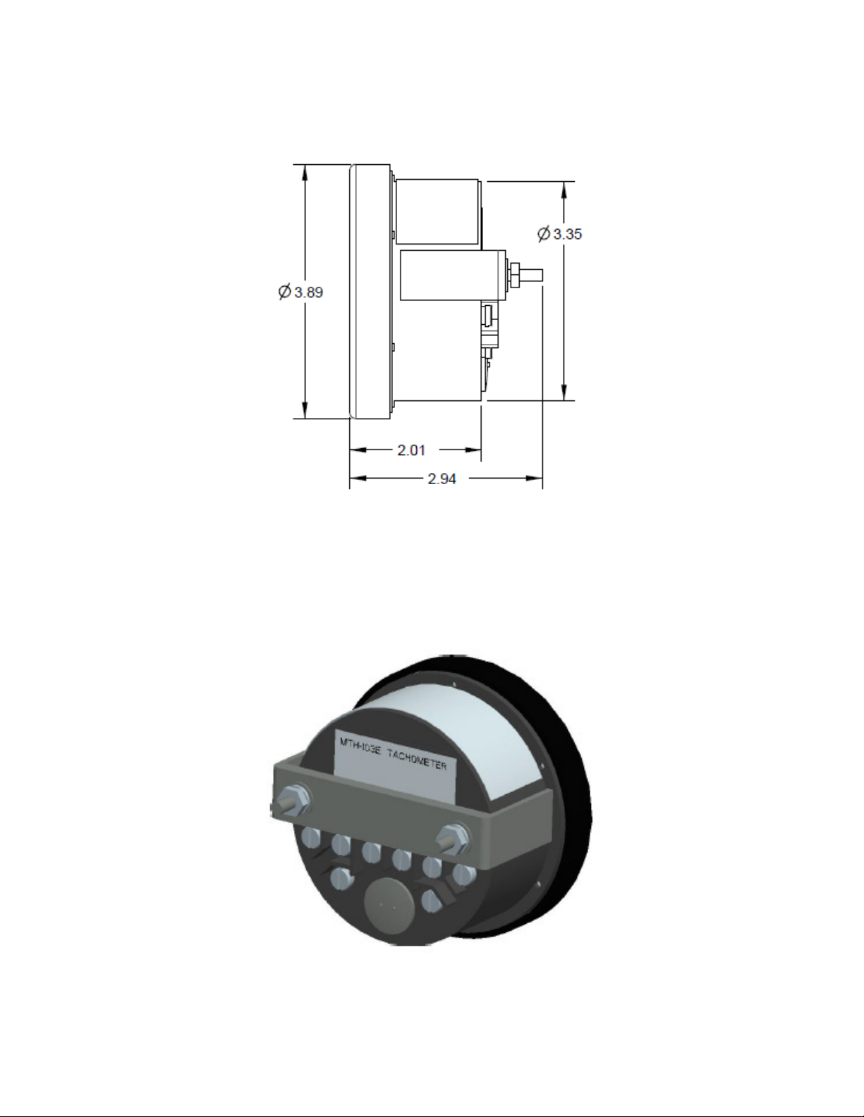
Installation:
The MTH-103E is designed to be panel mounted. The dimensions are shown below.
The MTH-103E includes a bracket for securing into the panel.
3
Page 5

Terminal Connections
All connections are made to terminals on the back of the unit.
Terminal screws to be tightened to 8 inch-pounds torque.
See pages 9 &10 for complete wiring information.
Programming Overview
4
Page 6

All programming is accomplished through the front keypad.
Below is a brief description of each key.
Press to enter or exit the configuration screens
Press to enter or accept values
Select up
Select down
Go back one screen
Select and advance to next screen
Initial configuration consists of the following steps:
1) Programming the # gear teeth
2) Selecting over / under speed setpoints (if required)
3) Pre-setting hourmeter (if required)
5
Page 7

Programming Instructions
Important: The MTH-103E must first be programmed prior to operation.
When initially powering up the unit, the display will first indicate the firmware version and then
go to the operational mode.
To configure each input, first go to the main programming screen by pressing the Menu /
Escape key:
Note: If a screen is displayed showing a keypad, this indicates that a security code has been
enabled. Please see “System Settings” section on page 7 for the description of setting a
security code.
The main configuration screen shows the following icons:
Gear Teeth Settings - for selecting number of gear teeth
Hourmeter Settings - configures hourmeter count up or count down
Alarm Settings - for enabling low / high alarms
Alarm Logs - for accessing alarm log info
System Settings - for selecting default display
Configuration of “Gear Teeth Settings”
Using the arrows on the keypad, select the “Gear Teeth Settings” icon and press enter.
Here, you will need to set the number of gear teeth for proper RPM display. The MTH-103E
will allow any number from 1 to 360 teeth.
Always use the right arrow key for selecting and advancing to the next screen.
6
Page 8

Pressing at any time during configuration will prompt you to save the changes.
Select “Yes” to save any changes made. Selecting “No” will not save changes.
Configuration of “Hourmeter Settings”
Using the arrows on the keypad, select the “Hourmeter Settings” icon.
The first screen will allow you to configure the hourmeter to either count up or count down by
pressing the up / down arrows to select, then pressing the right arrow to navigate to the
next screen. Here, you will be able to either leave the hourmeter to the current setting or preselect any number up to 99999 hours. Following this, you will be asked to save the changes.
Configuration of “Alarm Settings”
Using the arrows on the keypad, select the “Alarm Settings” icon.
Here, you can either enable or disable the RPM Alarm and select both underspeed (RPM
Alarm Low) and overspeed (RPM Alarm High) setpoints. Note that if underspeed is not
required, the parameter should be set to “0.” The next screen to the right will allow
configuration of the “Hourmeter Alarm” if required. This will allow you to preset an hourmeter
value that may be used to alert the user of maintenance required, for example.
System Settings
Using the arrows on the keypad, select the “System Settings” icon.
There are (2) display layouts available, either “Large RPM Digit” or “RPM + Hourmeter.”
Note that you are selecting the default layout type. You will be able to change the layout
during normal operation by pressing the left / right arrows.
After setting the layout type, pressing the right arrow will allow the user to either enable or
disable a “Security Option.” The security option allows the user to set a 4-digit security code
for locking out the programming function. If this is not required, select “Disable” and press the
right arrow. You will then be asked to save any changes.
If you would like to enable the security option, select “Enable” and press the right arrow. The
next screen will allow configuration of any 4-digit security code from 1000 to 9999. Pressing
“Enter” will allow the code to be set. After pressing the right arrow, you will be asked to save
the new settings.
Note that if the security code is enabled, the display will always ask the user to enter the 4digit code if the “Menu” key is pressed.
In case the security code is mis-placed or forgotten, there is a master code for gaining access to the programming function. The master
code is “5034381”
7
Page 9

Operation
Apply power from either:
a. A signal frequency generator or a magnetic pickup (minimum 4.0 VRMS;
maximum 15 VRMS) connected to terminals (A) and (B) (no polarity).
Or…
b. 9 – 30 VDC power source connected to terminals (1)(+) and (4)(–).
(minimum 1.5V RMS pickup input signal required).
The software revision number will display for one second when power is initially applied.
Alarm / Shutdown Output
The MTH-103E will alarm or shutdown when the RPM is above or below limits as specified. If
an alarm condition is met, an alarm indication on the display will blink and the digital output
will trip. The alarm / shutdown triggers a TRIAC rated at 150 mA for switching either an
annunciator input or an external relay. This TRIAC is similar to the SCR used in the previous
version MTH-103D in that current flow must be removed to reset the TRIAC. This can be
accomplished by providing a momentary contact closure across the (2) output terminals (5 &
6).
WARNING:
Terminal connection screws to be tightened to 8 inch-pounds torque.
The alarm / shutdown output should be tested monthly for proper operation, especially
if being used for engine overspeed shutdown or other critical function.
8
Page 10

9
Page 11

10
 Loading...