

Page 1
LST-100 and LST-100L
SELF-POWERED T ACHOMETER
Calibration Instructions
The LST-100 and LST-100L tachometers are normally factorycalibrated to the customer-specified number of sensing teeth or
discontinuities, sensing speed, and desired numerical display.
If necessary, turn to the reverse side of the card
to calculate Signal Frequency and Gate Time.
To calibrate the LST-100 or LST-100L:
1. Remove the sealing plug on the back of the housing.
2. Apply the calculated signal frequency to terminals A and B.
A Dynalco F-16 or F-15 signal generator is ideal.
3. Select the appropriate gate time range on the 4-position
switch.
side of card.
4. Adjust the vernier potentiometer for the desired display.
See below
See label on back of LST-100; LST-100L; or Item 3, reverse
.
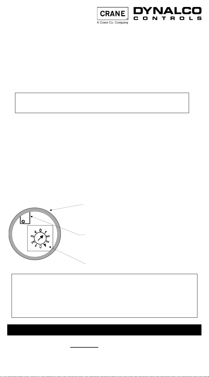
Shown with sealing plug removed
Vernier potentiometer
[clockwise to increase display reading;
counterclockwise to decrease]
4-position switch
Example:
1.Apply 3390 Hz to terminals A and B on tachometer (no polarity).
2.Turn the gate time range switch to (either) position number 1 to
select gate time range of 0.26 – 0.72 seconds.
3.Adjust the vernier potentiometer to obtain a display of 1800.
See label on back of LST-100, LST-100L for additional information
GATE TIME
CALCULATION
If 3390 Hz = 1800 RPM, then gate time is 0.53 seconds.
QUICK
}
(For example: 60/113 teeth = 0.53 sec. gate time)
60
Number of
Teeth
Assumes the pickup is “seeing” the
gear of interest directly, not through
{
a step up or step down ratio
.
Page 2
1. Calculating Signal Frequency (in Hz)
Multiply RPM times the number of teeth (or discontinuities), then
divide by 60. For example, sensing a ring gear with 1 13 teeth rotating
at 1800 RPM gives a frequency of 3390 Hz.
Signal Frequency in Hz =
Signal Frequency in Hz = = 3390 Hz
(RPM) x (Teeth or Discontinuities)
60
(1800 RPM) x (113 Teeth)
60
2. Calculating Gate Time (In seconds)
Divide the number to be displayed on the LST-100 or LST-100L
by the corresponding signal frequency.
Gate Time = = 0.53 seconds
.
1800 RPM
3390 Hz
3. Gate Time Range Selection on 4-Position Switch
Select either position for each number pair on the switch:
Position 1: 0.26–0.72 sec. Position 2: 0.72–1.43 sec.
Position 3: 1.43–2.85 sec. Position 4: 2.85–5.70 sec.
4. Pulse Rate Multiplier: Required gate time
divided by ten:
jumper terminals 4 to 5. The input pulse rate will be multiplied
by ten times. K Required gate time
divided by one hundred:
jumper terminals 5 to 6. The input pulse rate is multiplied by
one hundred.
Optional Calibration Method: On-engine
A. Select the appropriate gate time range on the 4-position switch.
B. Connect the magnetic pickup output to terminals A & B.
C. Adjust vernier potentiometer on LST-100 or LST-100L until its
display agrees with another precise digital tachometer.
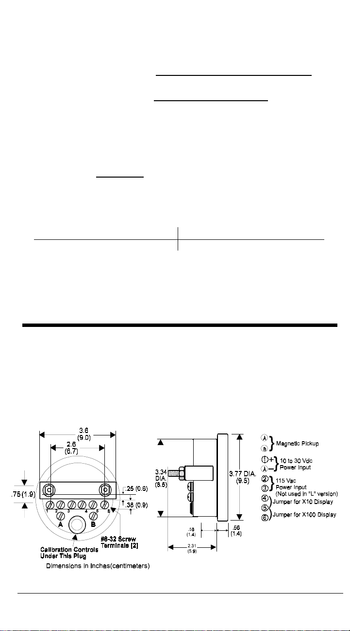
OUTLINE AND CONNECTION DRAWING
DYNALCO CONTROLS RESERVES THE RIGHT TO CHANGE THESE SPECIFICATIONS WITHOUT NOTICE.
Dynalco Controls, 3690 N.W. 53rd Street, Ft. Lauderdale, FL USA 33309
(954) 739- 4300 • Fax (954) 484-3376 • www.dynalco.com • mailbox@dynalco.com
© 2002 DYNALCO 145F-12034
LST-100 and LST-100L are trademarks of Dynalco Controls
 Loading...