

Page 1

Signal Powered Digital Indicator
LMD-120A
Installation and Calibration
The LMD-120A is powered from the 4-20 mA current that serves as the signal into
terminals 1 (+) and 2 (–). Do not make any other power connections to this unit.
K
This device can be connected as a simple current meter in any 4-20 mA current
loop in series with transmitters, controllers, and other 4-20 mA monitors.
Maximum loop burden is 100 ohms at 20 mA.
Calibration:
1. With 4 mA input, adjust ZERO ADJUST for desired reading at 4 mA.
2. With 20 mA input, adjust SPAN ADJUST for desired reading at 20 mA.
3. Repeat steps 1 through 2. Recalibrate as needed.
Note: With switch 4 off, ZERO ADJUST permits any initial reading from
–1000 to +1000; SPAN ADJUST permits a span adjust from 100 to 2000 counts.
K
With switch 4 on, the zero is adjustable from –10,000 to +10,000; the span is
adjustable from 1000 to 20,000 (fixed zero).
Intrinsic Safety: This instrument is CSA certified as intrinsically safe for Class I,
Divisions 1 and 2, Groups A, B, C, and D hazardous locations, if the signal feeding
the unit is derived from a safe source or through a safety barrier meeting entity
parameters of Vmax = 40 volts, Imax = 200 mA, Ci = 0, Li = 0.
© 2002 Dynalco Controls 145F-12032, Rev. 0
Page 2
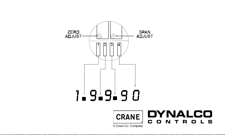
LMD-120A — View with the plug removed
Calibration controls under plug (rear)
Switches 1, 2, and
3 control decimal
points as shown.
Dynalco Controls, 3690 N.W. 53 St.
Ft. Lauderdale, FL 33309 USA
(954) 739-4300 • Fax (954) 486-4968
www.dynalco.com • mailbox@dynalco.com
Switch 4 adds a dummy
zero (fifth digit, fixed
zero) to extend range
1999 to 19990.
 Loading...