

Page 1

F-16
Signal Generator/Counter/Calibrator
Calibration Card
Generator and Counter Mode
Resolution: A. 0.1 Hz: 10–999.9 Hz
B. 1.0 Hz: 1000 Hz–20,000 Hz
Readout has automatic scale ranging.
Fast update rate of one reading per second (one second gate time)
Generator Mode
• Generates continuously adjustable frequency signal from 10 Hz to 20,000 Hz.
• One second gate time (update rate of reading) in both ranges.
• Output is a square wave, DC-coupled, nominal amplitude of 10 volts peak-to-peak, short
circuit proof. Enables calibration of Dynalco self-powered tachs, trips, etc.
Counter Mode
• Any input signal amplitude from 50 mVrms–50 Vrms
• Insensitive to signal amplitude. Responds only to frequency
• Waveform: Sinusoidal, square, triangular, or pulse
• Crystal controlled accuracy of readout
• Unipolar or bipolar since the input amplifier is AC coupled
Low Battery Indication
• A colon after the first and second digit,
and a decimal point after the third digit.
General information
• Power: Single 9-volt radio battery.
• For intrinsic safety use only:
batteries.
• Intrinsic safety: All circuits and electrical components operate at low energy levels
incapable of releasing sufficient electrical or thermal energy—under normal or abnormal
conditions—to cause ignition of hazardous atmospheric mixtures of pentane, ethylene, or
methane in their most volatile state.
Battery Replacement
• Snap-open plastic door in rear of F-16 gives quick access to 9 volt battery.
Eveready 1222, Mallory M1604HD2
0:1:5.7.9
1 :1:7.5 9
Low battery: displaying 0157.9
Low battery: displaying 11759
, or
Ray-0-Vac D1604
© Azonix-Dynalco 2002 p/n 145F-12028, Rev 2
Page 2
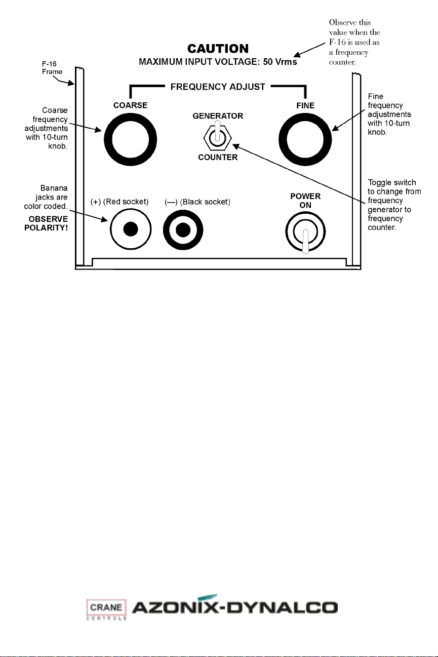
F-16 CONTROLS
CALIBRATION EXAMPLE
Determine setpoint value on an SW-50 Series Speed Switch — on the bench
J Turn on the F-16.
J Set the F-16 to a low frequency—below what would be expected to trip that
setpoint.
J Attach the red F-16 lead to Terminal 3 on the SW-50.
J Attach the black F-16 lead to terminal 2 on the SW-50.
J Make sure the F-16 is set to GENERATOR.
J Slowly increase the frequency on the F-16.
J Using an ohmmeter across each relay contact, in turn, determine the frequency
at which the relays change state.
Note: An overspeed relay will latch if terminal 4 is not grounded.
Change setpoint value on an SW-50 Series Speed Switch — on the bench
Remove the screws in the access holes for the required setpoint adjustment trim pots.
J Set the signal generator to the frequency at which the relay should change
state.
J Using a small, flat blade screwdriver, slowly adjust the trim pot for the
appropriate relay until the relay changes state.
• CW to increase the setpoint value
• CCW to decrease the setpoint value
J Decrease the frequency, then slowly increase it to verify that the relay trips at
the appropriate point.
Azonix-Dynalco, 3690 N.W. 53 Street, Fort Lauderdale, FL 3330 U.S.A.
(954) 739-4300 • Fax (954) 484-3376 • www.dynalco.com • mailbox@dynalco.com
 Loading...