

Dynacord DPS260 Owner's Manual
Owner’s Manual

www.dynacord.com
The lightning flash arrowhead symbol, within a
n
equilateral triangle is intended to alert the user to th
e
presence of uninsulated „dangerous voltage“ withi
n
the product’s enclosure that may be of sufficien
t
magnitude to constitute a risk of electric shock t
o
persons.
The exclamation point within an equilateral triangle i
s
intended to alert the user to the presence of importan
t
operating and maintance (servicing) instructions in th
e
literature accompanying the appliance.
1. Read these instructions.
2. Keep these instructions.
3. Heed all warnings.
4. Follow all instructions.
5. Do not use this apparatus near water.
6. Clean only with a dry cloth.
7. Do not cover any ventilation openings. Install in accordance with the manufacture’s instructions.
8. Do not install near heat sources such as radiators, heat registers, stoves, or other apparatus
(including amplifiers) that produce heat.
9. Do not defeat the safety purpose of the polarized or the grounding-type plug. A polarized plug has two blades
with one wider than the other. A grounding type plug has two blades and a third grounding prong. The wide
blade or the third prong are provided for your safety. If the provided plug does not fit into your outlet, consult an
electrician for replacement of the obsolete outlet.
10. Protect the power cord from being walked on or pinched particularly at plugs, convenience receptacles,
and the point where they exit from the apparatus.
11. Only use attachments/accessories specified by the manufacturer.
12. Unplug this apparatus during lightning storms or when unused for a long period of time.
13. Refer all servicing to qualified service personnel. Servicing is required when the apparatus has been damaged
in any way, such as power-supply cord or plug is damaged, liquid has been spilled or objects have fallen into the
apparatus, the apparatus has been exposed to rain or moisture, does not operate normally, or has been dropped.
14. Do not expose this equipment to dripping or splashing and ensure that no objects filled with liquids, such as vases,
are placed on the equipment.
15. To completely disconnect this equipment from the AC Mains, disconnect the power plug from the AC receptacle.
16. The mains
plug
of the power supply cord shall remain readily operable.
European Union and other European countries with individual national policies on the management of
WEEE) The symbol on the product or on its packaging indicates that this product may not be treated as
IMPORTANT SE
R
V
ICE INSTRUCTIONS
CAUTION: These servicing instructions are for use by qualified personnel only. To reduce the risk of
electric shock, do not perform any servicing other than that contained in the Operating
Instructions unless you are qualified to do so. Refer all servicing to qualified service personnel.
1. Security regulations as stated in the EN 60065 (VDE 0860 / IEC 65) and the CSA E65 - 94 have to be obeyed when
servicing the appliance.
2. Use of a mains separator transformer is mandatory during maintenance while the appliance is opened, needs to be
operated and is connected to the mains.
3. Switch off the power before retrofitting any extensions, changing the mains voltage or the output voltage.
4. The minimum distance between parts carrying mains voltage and any accessible metal piece (metal enclosure),
respectively between the mains poles has to be 3 mm and needs to be minded at all times. The minimum distance
between parts carrying mains voltage and any switches or breakers that are not connected to the mains (secondary
parts) has to be 6 mm and needs to be minded at all times.
5. Replacing special components that are marked in the circuit diagram using the security symbol (Note) is only
permissible when using original parts.
6. Altering the circuitry without prior consent or advice is not legitimate.
7. Any work security regulations that are applicable at the location where the appliance is being serviced have to be
strictly obeyed. This applies also to any regulations about the work place itself.
8. All instructions concerning the handling of MOS - circuits have to be observed.
NOTE: SAFETY COMPONENT ( MUST BE REPLACED BY ORIGINAL PART
)

Contents
Overview .............................................................6
Introduction .........................................................8
DSP 260 Features .................................................................... 8
Controls & Connection .......................................... 10
Front Panel ............................................................................ 10
Rear Panel ............................................................................. 14
Installation ............................................................................ 16
Mounting .................................................................................................... 16
Power Connection ........................................................................................ 16
Audio Cables .............................................................................................. 16
Balanced Input / Output Connections ............................................................. 16
Un-balanced Input / Output Connections ........................................................ 17
RS-232 ...................................................................................................... 17
Relay Contact Closure .................................................................................. 17
USB .................................................. ........................................................ 18
Connection to Amplifiers ............................................................................... 18
Input Level Adjustment ................................................................................ 18
Editing & Operation ............................................. 19
Factory Presets.................................................... ................... 19
User Presets – Standard Editing ............................................... 19
User Preset – Full Editing ......................................................... 19
Unpacking & Warrant y ............................................................. 19
Run-time Mode ................................................... 20
LCD Display ........................................................................... 20
Input Level Meters .................................................................. 20
Output Level Meters ................................................................ 20
Output Gain Reduction Meters .................................................. 21
Output Channel Mute Buttons................................................... 21
Output Channel Function Indicators .......................................... 21
Preset Recall .......................................................................... 21
Preset Store ........................................................................... 22
Edit ...................................................................................... 23
Standard Edit Mode ................................................................ 23
Full Edit Mode ........................................................................ 23
Parameters ............................................................................ 23
Input Channel Hi-Pass Filter .......................................................................... 24
Input Channel Parametric EQ ........................................................................ 25
Input Channel GEQ (Graphic Equalizer) .......................................................... 28
Input Delay ................................................................................................ 28
Routing ...................................................................................................... 29

Cross-Over (Output Channels) ...................................................................... 29
Parametric EQ (Output Channels) .................................................................. 31
Delay (Output Channels) ............................................................................. 31
Channel Level (Output Channels) .................................................................. 32
Channel Limiter (Output Channels) ................................................................ 32
Setup ................................................................ 33
Setup Menus .......................................................................... 33
Configuration .............................................................................................. 33
Input ......................................................................................................... 34
LCD ........................................................................................................... 34
Limiter Units ............................................................................................... 34
Metering .................................................................................................... 34
T emperature ............................................................................................... 34
Editing ....................................................................................................... 35
Lock - Front Panel Access ............................................................................. 35
System ...................................................................................................... 36
RS232 Port ................................................................................................. 36
Configurations of the DSP 260............................... 37
List and Detailed Descriptions .................................................. 37
Stereo 2 Way + Full Range ........................................................................... 38
3 Way Stereo .............................................................................................. 39
4 Way + FR ................................................................................................ 40
5 Way + FR ................................................................................................ 41
Free Configuration - Full Edit 2 in 6 Out .......................................................... 42
3 Way Stereo-Mono Sub+FR ......................................................................... 43
EQ Plot Images ................................................... 45
6dB PEQ Cuts Q Changes ......................................................... 45
6dB-Oct Shelves at 200Hz and 2kHz ......................................... 45
12dB PEQ Cuts Q Changes ....................................................... 46
12dB-Oct Shelves at 200Hz and 2kHz ....................................... 46
Bessel Filters ......................................................................... 47
Butterworth Filters .................................................................. 47
Hi Lo Pass Filters .................................................................... 48
Linkwitz-Riley Filters ............................................................... 48
PEQ Gains ............................................................................. 49
Operation Modes & Presets ................................... 50
Dimensions ........................................................ 52
Technical Specifications ........................................ 53
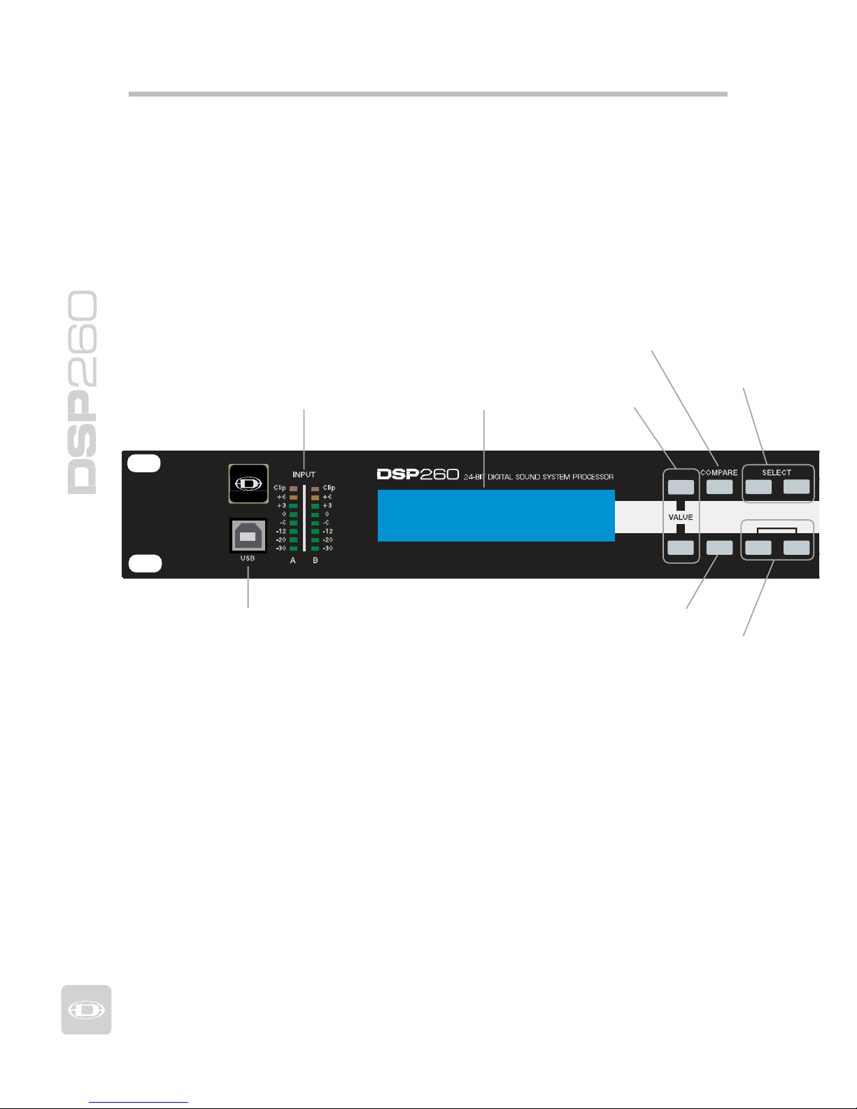
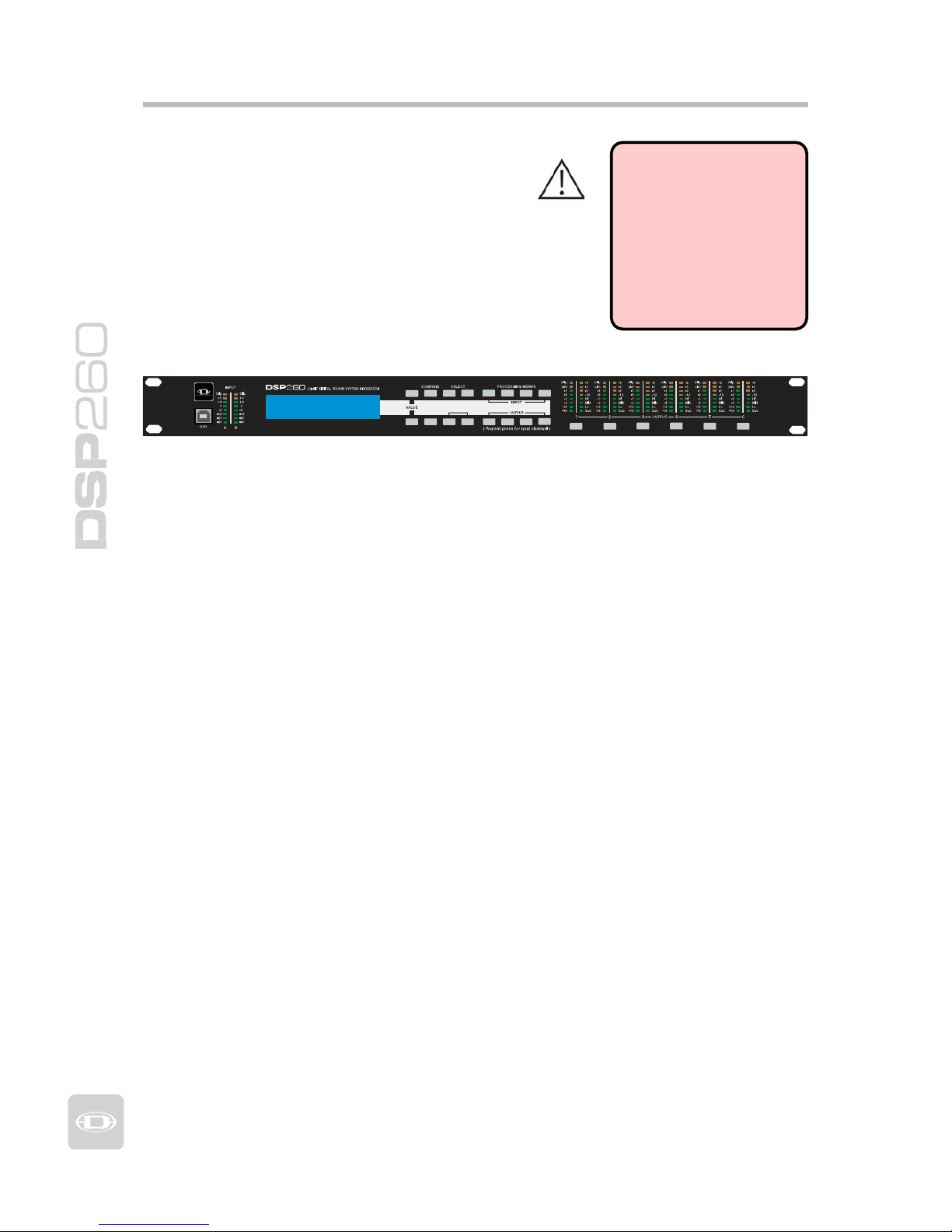
Overview
Compare / Edit
In
p
ut Meters
Dis
p
la
y
V
alue
Select Buttons
Dynacord DSP-260
Program:U01
(
FullEdit
(
2in. 6out
))
Edit
Setu
p
<
Store
>
Recall
USB Port
Setu
p
Store / Recall
6
Processing Menues for High
Pass Filter, Parametric EQ,
Gra
p
hic EQ and Delay
Output Gain Reduction Meters, Out
-
put Channel Function Indicators an
d
Output Level Meters
HPF
PEQ
GEQ Delay
X-Over
PEQ
Delay
Level
Mute
Mute
Mute
Mute
Mute
Mute
Output Control buttons for
Cross-Over, Parametric
EQ, Dela
y
and Level
Output Channel
Mute Buttons
7
Owners Manual
Introduction
Thank you for purchasing the Dynacord
DSP 260 Digital Signal Processor.
The Dynacord DSP 260 Digital System
Processor is a universal two-input, six-output
digital signal processor with the flexibility of
configuration to handle a multitude of audio
system needs and applications; installed sound,
house of worship, convention & meeting facilities,
concert touring, club, portable sound
reinforcement and more.
IMPORTANT NOTE
To achieve optimum performance and guard against
damage to the processor,
your sound system or yourself, please read, understand
and follow all of th e dir ections contained in this
Owner’s Manual. Failure to
do so may result in improper
performance, loss or injury.
Dynacord DSP-260
Program:U01
(
FullEdit (2in. 6out))
Edit
Setup
<
Store
>
Recall
HPF
X-Over
PEQ
PEQ
GEQ
Delay
Delay
Level
Mute
Mute Mute Mute Mute Mute
DSP 260 Features
The internal routing matrix can be configured as 2-way stereo + full-range, 3-way
stereo, 4-way mono + full-r ange, 5-way mono + full range, 3-way stereo with a
mono sub + full-range, 4-wa y stereo with mono sub and low frequency and finally
as a freely assignable 2 x 6 matrix router.
The DSP 260 replaces entire
racks o
f
signal processors previously needed to
properly configure and control sound reinforcement systems with a single
Analog Devices® SHARC™ DSP processor. The substantial advantages of the
DSP 260 over discrete si
g
nal
p
rocessin
g
racks include:
• 24-bit, 48kHz digital signal path
• No patch cables to fail or add noise
• Optimal gain structure throughout all stages of signal processing;
no gain matching from processor to processor.
• Recallable factory and user presets; instant system reconfiguration
for differing applications and performances.
• Easy, intuitive operation and editing with a PC and the DSP 260
Graphic User Interface Application.
Each DSP 260
Digital System Processor includes the following
si
g
nal processing blocks:
• Input VU Metering
• Analog or AES/EBU inputs
• 24-bit, 48kHz A/D converters
• Stereo Hi-pass filters
• Stereo 9-band parametric equalizer
• Stereo 31-band graphic equalizer (available as a software add-on
with V1.1 firmware - see www.dynacord.com for details)
• Stereo delay
8

Matrix Router
/ Mixer
• Two (stereo) inputs
• Summed left / right (mono) input
• Six assignable outputs
Outputs (each)
• Cross-over (hi-pass / low-pass filters), with selectable filter types
• 5-band parametric equalizer
• Delay
• Polarity
• Peak RMS detecting limiter
• Level & Mute
• 24-bit, 48kHz D/A converters
Additional features include:
• Electronically balanced XLR inputs and outputs
• -6dB switchable input level pad
• Contact closure interface for recall of up to eight selectable presets
• Front-panel USB port for connection to PC; preset editing and real
time parameter control and monitoring.
• Firmware updates
• FLASH memory for preset storage and in-field firmware upgrades
• Input level meters
• 192 x 32 back-lit graphic LCD display
• LCD navigation / editing controls
• DSP block navigation short-cut controls
• Output level meters
• Output gain reduction meters
• Output assignment display LEDs; sub, low, mid & high
• Output channel Mute controls
• Auto-ranging internal power supply; 100 – 240VAC, 50 – 60Hz
• Standard IEC A.C. inlet with external, replaceable fuse
9
Owners Manual

Controls & Connection
Front Panel
4 6 8 9 12 13 14 15 20 21
1 2 3 5 7 10 11 16 17 18 19 22 23
1 – USB Connector
USB 1.0 port for connection to a PC running Windows XP or Vista. With a
connected PC you may run the DSP 260 Editor Graphic User Interface Application.
The DSP 260 can be operated, edited and configured for installation with an easy
to use, intuitive interface. Any available firmware updates downloadable from
www.dynacord.com can be loaded via the USB port as well; allowing for easy infield u
p
dates.
2 – In
p
ut Level Meters
The DSP 260 does not itself have input level controls. Proper input level
adjustment is accomplished by setting the output level from the (L / R) bus
outputs from the connected mixer (or other audio output device), as the vast
majority of today’s mixer-outputs are dBu calibr ated. When the mixer is operating
at optimal levels, so is the DSP 260. The input meters monitor the input level of
either analog or AES-EBU inputs, depending on the input mode selection set in
the Setu
p
Menu.
Optimal signal-to-noise performance
is
obtained when the nominal (aver age),
input level consistently lights the +3dBu (green) and / or +6dBu (Yellow) LED
indicators. As the DS P 260 is a di gi tal audi o devi ce – and di gi tal clippi ng p roduce s
very unpleasant results, the Clip (red) LED should not light. If the DSP 260’s input
does cli
p
,
reduce the output level o
f
the connected mixer.
3 – LCD Displa
y
The back-lit, 192 x 32 graphic LCD display allows for operation and editing o
f
the
DSP 260 without the need for an attached PC. The contrast can be set in the Setu
p
Menu for varying lighting conditions and viewin
g
ang
les.
The LCD displ a y wor ks i n con ju ncti o n with Menu buttons, Select buttons and
Value buttons - to
op
erate, navigate and edit the DSP 260’s
p
arameters.
In Run mode, the LCD displays the
number and name o
f
the currently selected
factory or user preset. Pressing the Recall or Store buttons switches to their
respective menus. Pressing the Edit or Setup menu buttons switches the display
to the last edited
p
arameter.
In Edit and Setup mode, the top
line o
f
the LCD display shows the currently
selected parameter edit screen. Use the Select buttons to activate the top line of
the display, and the value buttons to scroll through available parameter edit
screens.
10

4/5 – Value Up/Down Buttons
Depending on the current LCD screen, the Value Up/Down Buttons performs
the followin
g
function:
R
ecall – Select forwards/backwards through the stored preset list to
select a preset to be recalled to current memory.
Store – Select User Preset destinations forwards/backwards to select a
destination for the currently edited preset, scroll forwards through ANSI
character
set to name
p
reset.
Edit / Setup – Scroll forwards/backwards through Edit / Setup screen
s
when the top line of the LCD screen is active. Scroll forwards throug
h
values for the selected
p
arameter in an Edit
/
Setu
p
screen.
6 – Edit / Com
p
are Button
Pressing the Edit button while in Run mode places the current preset in Edit
mode and the Edit button lights. The LCD display shows the last edit screen
that was selected. From this point, any edit screen can be displayed and
altered.
Pressing the Edit button again
“compares” the edited preset, if parameters
have been altered, to the original un-edited preset. This compare function will
audibly switch between the altered parameters and the previously stored
settings, allowing you to hear the effect of any DSP changes that have been
made. Use this
feature to monitor
prog
ress in editin
g
or
creating presets.
Subsequently recalling a new preset will prompt you to save cha ng e s, w h ich
y
ou may do or not.
7 – Setu
p
Button
Pressing the Setup button while in Run mode displays the Setup menus in the
LCD display and the Setup button lights. In this mode, any Setup menu can
be displayed and altered. Changes made to Setup menu items are saved
automaticall
y.
T
o exit Setup mode, press the Setup button again.
The
L
CD display will revert
to Run mode.
8 – Select < Button
The Select < button is pressed to navigate backwards through Edit, Setup
and / or Recall menu displayed. The button cycles through all available value
fields in a screen and wra
p
s around from first to last.
9 – Select > Button
The Select > button is pressed to navigate forwards through Edit, Setup and /
or Recall menu displayed. The button cycles through all available value fields
in a screen and
wraps around from last to first.
11
Owners Manual

10 – Store Button
Pressing the Store button while in
Run
mode displays the Store Preset screen
in the LCD display and the Store button lights. In this screen edited presets
can be named and saved to a user preset location. Pressing the Store button
a
g
ain completes the preset save operation.
T
o exit without storing the current preset, press the Edit or Setup buttons to
return to the Run mode screen.
11 – Recall Button
Pressing the Recall button while in
Run
mode displays the
R
ecall Preset screen
in the LCD display and the Recall button lights. In this screen, any of the 60
factory and 20 user presets can be recalled into current memory. Pressing the
Recall button again completes the preset load operation and returns the LCD
dis
play
to Run mode.
T
o exit without storing the current preset, press the Edit or Setup buttons to
return to the Run mode screen.
12 – Input HPF Button
Pressing the HPF button places the current preset in Edit mode and jumps to
the Hi-Pass Filter screen of Input A. Subsequent button presses toggle the
dis
play
between Input A and Input B.
13 – Input PEQ Button
Pressing the PEQ button places the current preset in Edit mode and jumps t
o
the first screen of the Input Parametric Equalizer. Subsequent button presse
s
toggle the display between Input A and Input B.
14 – Input GEQ Button
Pressing the GEQ button places the current preset in Edit mode and jumps t
o
the the Input Graphic Equalizer screen. Subsequent button presses toggle th
e
display between Input A and Input B.
15 – Input Delay Button
Pressing the Delay button places the current preset in Edit mode and jumps
to the Input Delay screen. Subsequent button presses toggle the display
between In
put
A and Input B.
16 – Output X-Over Button
Pressing the X-Over button places the current preset in Edit mode and jumps
to the first Output Channel Cross-Over screen. Subsequent button presses
ste
p
through the six output channels.
12

17 – Output PEQ Button
Pressing the PEQ button places the current preset in Edit mode and jumps t
o
the first Output Parametric Equalizer screen. Subsequent button presses ste
p
through the six output channels.
18 – Output Delay Button
Pressing the Delay button places the current preset in Edit mode and jumps
to the Output Channel Delay screen. Subsequent button presses step through
the six out
p
ut channels.
19 – Out
p
ut Level Button
Pressing the Level button places the current preset in Edit mode and jumps to
the Output Channel Level screen. Subsequent button presses step through
the six out
p
ut channels.
20 - Out
p
ut Level Meters
Each output channel has an eight-segment output level VU meter. Meter
response characteristics can be selected in the Setup menu: Normal F ast,
Peak-Hold Slow Decay. The yellow segment indicates that limiti ng is bei ng
applied to the output channel. The red segments indicates clipping of the D/A
converters and should be avoided by adjusting the Output Level of the output
channel. It is important to understand how the meters work and what they
are displaying. The Output Meters are displayed as “dB to Limiter Threshold”.
In other words, these meters will display the headroom between the output
level and the limiter threshold. When viewe d in co n ju n ction with the Gain
Reduction meters, this provides a complete display of level and headroom
before and after limiting has been engaged to allow system levels to be
o
p
timized.
This also means that the output
metering will be displayed differently
depending on the limiter threshold setting.
21 – Output Gain Reduction Meters
Each output channel has a four-segment gain reduction meter that shows the
effect o
f
the output channel Limiter on output level
;
from 0dBu to -12dBu.
22 – Output Channel Mute Buttons
Each output channel has a lighted Mute button. Pressing the Mute button
turns off the output of that channel. The button lights red as an alert. Press
the Mute button a
g
ain to restore the output channel’s signal.
Output channels may also be
muted from the DSP 260 Graphic User Interfac
e
Application, if the u nit is conne cted to a PC. Muting a channel in any windo
w
of the application will light the channel Mute button on the front panel of th
e
unit as well.
13
Owners Manual
23 – Output Channel Function Indicators
Each output channel has a four-segment function display for informational
purposes only . F or any given configuration possible with the DSP 260, an
output channel may be identified as a sub, low, low/mid, mid, mid/hi, hi or
full range output. One or two adjacent LED are displayed to indicate all
p
ossible output bandpasses.
(
Full range is indicated b
y
no
lit LED’s.)
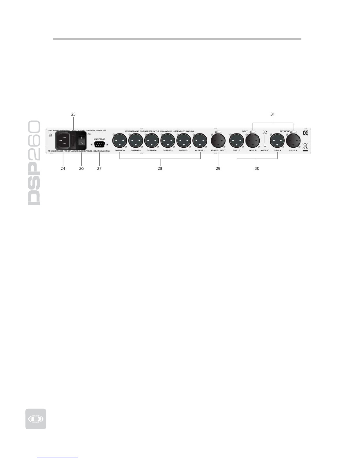
Rea r Panel
24- A.C. Inlet
The DSP 260 features a standard IEC A.C. inlet that will accept universal
power cords. The DSP 260 power supply is auto-ranging and can accept
voltages from 100 - 240VAC, 50 – 60Hz. Only A.C. cords approved for use in
y
our country should be connected to the DSP 260.
25 – A.C. Fuse
The A.C. inlet includes a fuse holder that contains the mains fuse as well as a
spare fuse. If necessary, replace the fuse only with a specified 5x20mm,
T800mA, L250V replacement. Disconnect A.C. power before replacing a fuse.
Before turning the unit back on, assess the condition of the A.C. receptacle
powering the DSP 260. If fuses continue to blow, refer servicing of the DSP
260 onl
y
to qualified service
p
ersonnel.
26 – A.C. Power Switch
The A.C. power switch turns
p
ower to the DSP 260 On and Off.
27 – Link/Rela
y
Interface
The operating mode of this dual purpose interface is selected in the Setup
menu. O
p
erating modes are:
RS-232
I
nterface – Used to link two DSP 260s together in a Master /
Slave setup. Connection is made via a standard 9-pin null-modem serial
interface cable with fem al e connectors.
Contac
t
Closure Port – Eight contact closure pins plus ground for
interfacing to 5 V contact closure systems. Each pin can be assigned a
preset that is recalled when voltage on that pin is detected. The lowest
p
in number takes priorit
y
in
multiple controller systems.
14

28 – Balanced XLR Outputs
Each output channel has an electronically balanced XLR connector for
connection to system amplifiers. Each output channel can output different
frequency ranges dependin
g
on
its assignment and cross-over settings.
Care must be ta
k
en to assure that each output is connected
to an appropriate amplifier and loudspeaker to avoid damage
or unexpected results. Note that a new preset may change
the assignment of channel and its frequency range. For
instance an output assigned to Hi frequency speakers in one
preset, may be assigned as a sub output in another. See
“
Configurations of the DSP 260”.
29 – AES/EBU Digital Input
In addition to the analog audio inputs, an AES/EBU digital stereo input is
provided and selectable in the Setup menu. The input conforms to IEC
standard 60958 Type I. Connections must be made with three-conductor,
110-Ohm, twisted pair cablin
g
and an XLR connector.
30 – Balanced XLR Thru
Each analog audio input is connected to an electronically buffered and
balanced output as a through connector. The signal does not undergo any
digital conversion or processing. These connectors are used to pass input
audio to a second DSP 260 used as a slave or to other audio inputs in the
s
y
stem.
31 – Balanced XLR In
p
uts
Each input has an electronically balanced, locking XLR connector. In stereo o
r
dual modes, connections to both inputs must be made. In mono modes, onl
y
one connection need be made
,
typ
icall
y
to Input A.
32 – -6dB Pad
Input levels to the DSP 260 can be reduced -6dB prior to the A/D converter t
o
compensate for higher-level output from mixers and other audio devices. Fo
r
ideal signal to noise performance when connecting the DSP 260 to high outpu
t
level devices engage the -6dB pad rather than turning down the output of th
e
connected device. The DSP 260’s Input Level Meters (2) will indicate incoming
si
g
nal level and whether attenuation is required.
15
Owners Manual
Installation
For proper operation, all directions regarding installation and connection must be
followed.
Mounting
The DSP 260 should be mounted in a rack-mount enclosure or rack rails. The
unit is 1RU tall by 14” (353mm) deep. Proper clearance for air circulation
around the unit must be provided. Do not block any vent holes on the unit.
For secure mounting and electrical insulation, correct r ack screws must be
used – #10-32 screw with plastic / nylon cup washer. All four mounting points
provided by the rack ears must be secured.
Power Connection
The DSP 260 must be connected to A.C. power only by means of the provided
IEC A.C. cable or by a power cable provided by the dealer / installer to match
the configuration of your country or region. The DSP 260 must only be
connected to a properly wired, three pin, grounded A.C. outlet. A.C. power
must range from 100 – 240VAC, 50 – 60Hz. The DSP 260 internal power
supply is an auto-ranging design; no adjustments are necessary to configure
it for proper A.C. power.
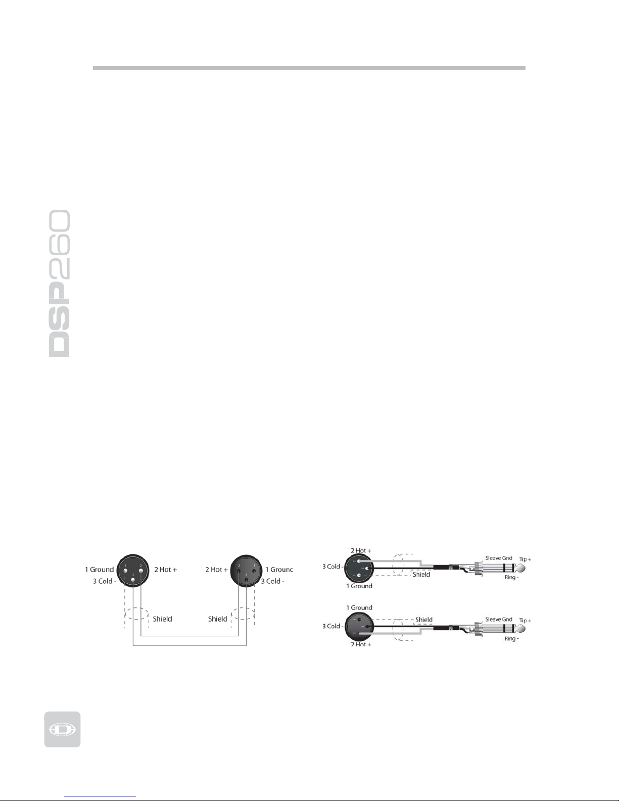
Audio Cables
Always use correctly shielded audio cables when connecting to the DSP 260.
Balanced Input / Output Connectio ns
To minimize induced noise caused by audio cables and to maximize the length
of cables used, balanced connections are strongly advised for both Inputs and
Outputs. The XLR jacks provided on the DSP 260 are configured as pin 1
ground, pin 2 hot (+), pin 3 cold (-). Cable shielding must be connected to
pin 1. XLR – XLR cables or ¼” tip-ring-sleeve – XLR cables can both be used
for balanced connections to the DSP 260.
16
Un-balanced Input / Output Connections
Un-balanced connections can be made to the DSP 260, although induced
noise from cabling may be increased. Cables should also be less than 15”
(5m) in length. Unbalanced connections can be 6dB lower in level as well. To
match the audio level obtained with a balanced connection, it is necessary to
tie pin 3 to ground at the XLR connector. This may increase noise.
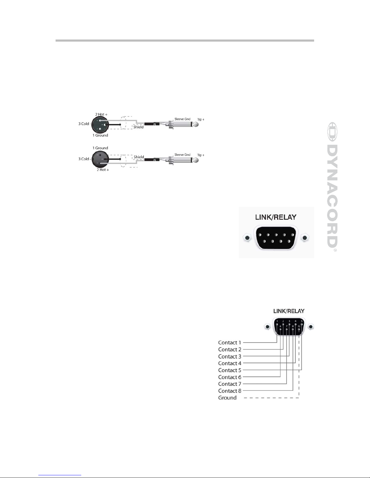
RS-232
Two DSP 260s can be used in combination as a
Master / Slave for managing larger sound
reinforcement systems. A 9-pin D-sub connector is
provided on the rear of each unit for data line
connections. A standard female-to-female RS232
cable that conforms to the null modem wiring
convention is used to connect the two units. Cable
length should be kept to less than 45 feet (15m) for
the most reliable operation. These cables are readily
available at lo cal computer dealers.
Operation o
f
the DSP 260 9-pin port for RS-
232 connections is selected in the Setup menu.
Relay Contact Closure
The same 9-pin port used for RS-232
connection to another DSP 260 can
alternately be used to recall presets
from relay contact closures. Pins 1 – 8
are the input lines and pin 9 provides
the ground reference. When the DSP
260 detects a connection between pin-9
ground and pins 1 – 8, as completed by
an external relay, a preset assigned by
the user to pins 1-8 is recalled into
memory and the DSP 260 returns to
runtime mode.
17
Owners Manual
 Loading...