

Page 1

Page 2

Page 3

INTRODUCTION
1. INTRODUCTION
Preamble
Thank you for choosing the DYNACORD PROANNOUNCE System. With the PROANNOUNCE System you
purchased a high-quality product which is going to satisfy your highest demands. This extraordinarily flexible and
versatile system allows the configuration of either small or complex installations as well. Most functions are realized
through software modules, which - when compared to conventional PA-systems – not only reduces the amount of
cabling but also the costs. Next to extensive audio signal generating and distribution functions, the PROANNOUNCE
system provides ample control functions. On one hand, these functions offer the possibility to register and rate
external events, as well as to control different external components, on the other hand. Boolean operations and
relations to the internal state of the system can be programmed as well.
To be able to take advantage of all possibilities that are offered by the PROANNOUNCE system, we would like to ask
you to read this handbook carefully. For getting a quick overview about the PROANNOUNCE system's components
and functions, we recommend consulting the chapter System Description.
Owner’s Manual
This handbook provides all the information that is necessary for planning and installing a PROANNOUNCE system.
The handbook is structured in different chapters, each explaining a specific component or function. Thus, you can skip
a section, if it is of no relevance for your particular application. The following table lists all chapters included in the
handbook. It is meant as a guide for finding relevant information as quickly as possible.
1. Introduction Notes on how to use the handbook
2. Operation Instructions Precautions, operational conditions, environmental conditions, location,
initial operation, maintenance and service
3. System Description Overview of all components (appliances), audio and control functions of
the PROANNOUNCE system
4. Installation Notes on how to install the PROANNOUNCE DESIGNER
configuration software
5. Single Device Descriptions Detailed descriptions of all PROANNOUNCE components: central unit with
modules, paging stations, power amplifiers, monitoring system
6. Appendix Notes on how to configure the hardware, wiring, and initial operation
PROANNOUNCE System User Handbook 1.1 1-1
Page 4
OPERATION INSTRUCTIONS
f
t
2. Operation Instructions
2.1 Safety Instructions
IMPORTANT SAFETY INSTRUCTIONS
CAUTION
RISK OF ELECTRIC SHOCK
DO NOT OPEN
WARNING:
DO NOT EXPOSE THIS APPLIANCE TO RAIN OR MOISTURE.
AVI S: RISQUÉ DE CHOC ELECTRIQUE. NE PAS OUVRIR.
1. Please carefully read all instructions.
2. Keep the instructions at a safe place, so that they are at hand for further reference.
3. Observe all warnings and precautions, whether attached to the appliance or within the owner's manual.
4. Do not expose or operate the appliance next to water or in environments with high humidity.
5. Do not cover any ventilation louvers. Mind manufacturer’s instructions when installing the appliance.
6. For maintenance and servicing, please refer to qualified service personnel only.
The symbol of a flash within an equilateral
triangle is to alert the user to the presence o
uninsulated dangerous voltage within the
product's enclosure that may be of sufficien
magnitude to constitute a risk of electric
shock to persons.
The symbol of an exclamation mark within an
equilateral triangle is to alert the user's
attention to the presence of important operating and maintenance (servicing) instructions
in the literature accompanying the appliance
PROANNOUNCE
System User Handbook 1.1 2-1
Page 5
OPERATION INSTRUCTIONS
CAUTION !
1. To prevent the risk of fire and shock hazard, do not expose any appliance or module high humidity or water.
2. Make sure that no alien objects enter the appliances or get in contact with the modules – especially no metal parts
– since this would very likely cause dangerous electric shock and/or malfunctioning. There are no userserviceable parts located inside the appliances or on the modules. Opening appliance enclosures and/or rack
shelf systems can lead to dangerous shock hazard. Do not open or try to reach inside the enclosures of
appliances. Leave installation, servicing, maintenance, and any other works on the appliances or the rack shelf
system to qualified service personnel only.
3. When exposing appliances/modules to extreme temperature changes, i. e. when moving them from the outside
into a warm room, condensation may occur. If so, it is necessary to wait before use until the devices gained room
temperature.
4. Under no circumstance place any liquid-containing cans, glasses, mugs, etc. on top of an enclosure. In case any
liquids or foreign obstacles entered the enclosure of an appliance, immediately unplug the device from the mains
supply and have it serviced.
5. Make sure that appliances/modules are always provided with sufficient ventilation. Do not expose devices to
direct sunlight or any other heat-radiating source.
6. Do not expose appliances/modules to extreme dust or humidity. Operating the system under environmental
conditions like these can lead to severe damage through fire or cause bodily harm to the operator.
7. Make sure that the stated mains voltage is in accordance to the specifications of your mains supplier.
Mismatching will cause severe damage to all appliances/modules.
8. Make sure that mains cords and/or any other cabling are not damaged or being jammed by the turning frame or
any other movable parts of the rack shelf. Damaged cables can lead to fire hazard and/or can be the cause for
electric shock.
9. The mains cord of the rack shelf installation is supplied with a 3-pole plug to minimize the risk of electric shock. It
should only be connected to a grounded wall outlet. Under no circumstances insulate the ground contact. When
using an extension cord, always use a 3-pole grounded cable. When using multi-outlets for distributing, make sure
that the wall outlet's capacity is not exceeded, since this could lead to fire hazard and/or can be the cause for
electric shock.
10. The DPM 4000 contains a lithium-type battery to provide the internal clock with power. The lifetime of this batterytype spans approximately 10 years. When the battery's voltage drops below a certain minimum, an according
message appears on the paging station display. In this case, the battery has to be exchanged by an EVI Audio
GmbH authorized service technician. Under no circumstances try to exchange the battery yourself!
CAUTION! There is a severe risk of explosion when incorrectly exchanging the battery. Only replace with
the same type of battery or one especially recommended by the manufacturer. For
environmental awareness: Take care of used batteries following the manufacturer's advice.
11. Obeying the VDE-regulation DIN VDE 0800 is necessary when installing and operating 100V-loudspeaker
systems. Especially with 100V-loudspeaker systems that are part of an emergency alert installation, protection
measures have to be in accordance with safety class 3 regulations.
CAUTION! During operation, speaker group connectors (POWER OUTPUT) may carry shock hazard output
voltages (>34V peak value). Thus, the installation of the connected loudspeaker groups has to in
accordance to security standards and regulations as stated above.
12. Make sure to establish all connections before operating the system. Connecting/disconnecting cables during
operation can cause malfunctioning or damage to the correspondent appliances.
2-2 PROANNOUNCE System User Handbook 1.1
Page 6

OPERATION INSTRUCTIONS
2.2 Operation Instructions
2.2.1 Central Unit DPM 4000
According to its specified capabilities and specifications, the DPM 4000 central unit can be used to control and monitor PA- and
paging systems in buildings, but also to operate professional audio systems.
The DPM 4000 central unit is not an independent device. For its operation, at least the following is necessary:
1. A power supply unit (24 V / 4 A) (24 V / 12 A), preferably of the DPP 4000 – Series, depending on the power
consumption of the entire system.
2. When the installation includes paging stations:
- the desired amount of paging stations of the DPC 4000 – Series (max. 16)
- all required cables.
3. When the unit's audio section is utilized:
- power amplifiers, preferably of the DPA 4000 – Series, including cabling
- loudspeaker systems including cabling
4. When the integrated real-time clock is going to be synchronized to the DCF77–timesync-signal:
- an active DCF77–antenna for reception (NRS 90193) including cables
This feature is only available in areas where DCF77-reception is strong enough.
5. When slave clocks need to be synchronized:
- the required amount of slave clocks (max. 40) including cabling
Additionally, a PC providing the following features is needed for configuration purposes and operation:
- PC computer system with Pentium processor (min. 90 MHz) and Windows 95/98/NT
- 16 MB of RAM
- 1 hard disk offering free space of at least 5 MB
- 1 x 3.5” floppy drive, 1.44 MB
- 1 mouse
- 1 monitor (with a resolution of at least 800 x 600 pixels) with VGA-graphics board, 256 colors
- 1 serial port RS-232 with serial cable
- PROANNOUNCE Designer configuration software
- 1 CD ROM drive
All necessary cables, plugs, connectors or adapters for establishing connections are available through EVI Audio
GmbH. Our entire accessory assortment with order-numbers is included in the corresponding owner's manuals as well
as in the PA-systems price lists.
PROANNOUNCE
System User Handbook 1.1 2-3
Page 7

OPERATION INSTRUCTIONS
2.2.2 DPA 4000 Power Amplifier
Especially designed for it, the DPA 4000 Series power amplifiers optimally match the PROANNOUNCE system. Thus
guaranteeing trouble-free installation and operation.
The power amplifiers are "stand alone" devices, offering the opportunity for them to be operated together with several
other pieces of equipment, as long as all valid specifications and applicable instructions for the installation are being
observed.
2.2.3 DPC 4000 Paging Stations
Especially designed for it, the DPC 4000 Series paging stations optimally match the PROANNOUNCE system. Thus
guaranteeing trouble-free installation and operation.
The paging stations cannot be used as "stand alone" devices. At least a DPM 4000, a 24 V power supply plus all
necessary cabling is needed to build-up a minimal installation.
Configuration and operation is accomplished through the DPM 4000 central unit.
2.2.4 DCS 400 Control System
The DCS 400 control system – consisting of a DCS 401 control module, a DCS 408 relay module 100V, a DCS 409
control-relay module, DCS 412 logic input module and DCS 416 analog I/O module – cannot be used as a "stand
alone" system. At least a DPM 4000, a 24 V power supply plus all necessary cabling is needed to build-up a minimal
installation.
According to their technical specifications, it is possible to incorporate the modules of the DCS 400 system as follows:
- DCS 401: control module for all other DCS 400 modules
query of 2 rotary encoders
- DCS 408: 5 floating switches for 100 V loudspeaker lines
- DCS 409: 5 floating switches for control signals (DC voltages, 24 V)
or for audio signals at line level
- DCS 412: query and monitoring of 12 floating control voltages
(logic signals up to ±31 V)
- DCS 416: 8 analog inputs for the query of control voltages (0 – 10 V)
8 analog outputs to output control voltages (0 – 10 V)
- DCS 420: Monitor Manager with loudspeaker, headphones socket,
7-segment display, and metering instrument
Configuration and operation is accomplished through the DPM 4000 central unit.
2.2.5 DPP 4000 Power Supply Units
Especially designed for it, the DPP 4000 Series power supply units optimally match the PROANNOUNCE system,
guaranteeing trouble-free installation and operation.
The power supplies are "stand alone" units, which offers the possibility to utilize them to feed other equipment with 24 V
supply voltage, as long as all valid specifications and applicable instructions for the installation are being observed.
2-4 PROANNOUNCE System User Handbook 1.1
Page 8

OPERATION INSTRUCTIONS
2.3 Operation Location
The appliances are exclusively meant for the installation in 19" rack shelf systems while the modules can also be
installed in an appropriate wall junction box. When installing the system, the safety regulations that are mentioned in
chapter 2.1 have to be observed.
It is particularly important that the following environmental conditions are provided:
- ambient temperature at the installation site – which also includes inside the rack shelf system – is not to exceed 40°
C. If necessary, the rack shelf system has to be supplied with forced ventilation or air conditioning.
Heat sources like power amplifiers, etc. – especially when they are mounted underneath the appliance – can increase
the ambient temperature to an exceeding degree, although the average temperature within the rack shelf system may
stay below 40° C.
- The installation site should not suffer from increased dust and moisture.
- The radiation of direct sunlight or other heat sources should be avoided.
- During operation, rear connectors have to be covered, since they partly conduct voltages that could endanger your
life.
- Ventilation louvres are not to be covered by any other installed gear. Therefore, it is reasonable to install a 1 HU
ventilation blind above the correspondent appliance.
- The installation site should not be subject to vibration.
2.4 Excluded From Warranty
Damages, malfunction, or obstruction of certain performance features resulting from the following causes are excluded
from the warranty.
- improper or erroneous maintenance by the customer
- changes or alterations without written consent
- operation outside of the environmental conditions specified for this product
- operation outside of electrical specifications
- improper installation
- damage during transportation because of improper packaging by the customer
Repair, replacing used batteries, altering, and retrofitting extensions is only admissible if EVI Audio GmbH or one of its
authorized service centers or maintenance technicians carry out these tasks.
PROANNOUNCE
System User Handbook 1.1 2-5
Page 9
SYSTEM DESCRIPTION
3. System Description
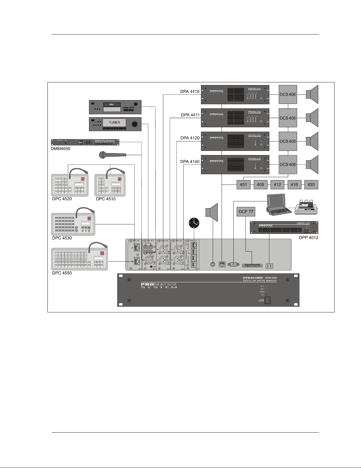
This chapter provides an overview of the general configuration of the PROANNOUNCE system and its most important
functions. The following block diagram shows a typical PROANNOUNCE system installation including the DPM 4000
central unit, paging stations, audio equipment, amplifiers, power supply unit, relay board assemblies, loudspeaker lines,
and control board assemblies for external signals.
figure 3.1 PROANNOUNCE System
3.1 General Overview
The digital PROANNOUNCE manager DPM 4000 represents the central unit of the system. It is used to control and
monitor all connected components via several serial interfaces. The chapter Single Device Descriptions contains all
necessary information about the DPM 4000 and its available modules.
The kind and amount of connected audio sound sources, amplifiers, and relay board assemblies are extremely
variable. This allows configuring the system to basically match any requirement. The system is capable of managing up
to 16 paging stations and up to 100 output lines. More than 150 control inputs and outputs are available for controlling
and monitoring purposes providing the possibility to generate and manage logic levels and analog levels as well. For
detailed information, please refer to the chapter DCS 400 Control System.
Configuration and documentation of a PROANNOUNCE system installation is established through the use of the
PROANNOUNCE Designer software – a comfortable graphical user interface that runs on a PC under Windows
95/98/NT. This allows changing the system’s setup at any time to meet new requirements, without the need to alter the
actual installation. The PC has to be connected to the system only when loading or changing its configuration. During
PROANNOUNCE System User Handbook 1.1 3-1
Page 10

SYSTEM DESCRIPTION
normal operation, PC-interaction is not necessary. Anyway, in most cases the permanent connection of a computer
bears benefits, like displaying detailed status reports or the printing of protocols. It also offers the possibility for remote
diagnosis and remote maintenance via modem.
3.2 Audio Routing
The DPM 4000 employs a digital audio matrix providing 4 inputs and 4 outputs. Additional matrix junctions for the
integrated gong and alarm signal generators, the vocal recording/playback unit, and the lock-on of the pilot tone and its
evaluation are incorporated. All input signals and internally generated signals can be freely mixed inside the matrix and
outputted through the 4 amplifier channels. Routing speaker lines to these amplifier channels is achieved via the relaymatrix, which offers up to four separate audio buses simultaneously, while the DPM 4000 takes over the management
of all these signals according to their priority.
Next to connecting paging stations, the audio inputs also serve for the connection of other audio sound sources, like
microphones, mixers, CD-players, cassette decks and DAT-recorders, tuners, etc. Several different input modules are
available to optimally adjust and match signal levels and connections.
3.3 Volume And Tone Controls / Delays
The PROANNOUNCE system provides individual volume controls for each input, output, and paging station. Even the
internal audio sources, like gong/alarm tone generators, voice message playback, and pilot tone generator employ
individual level controls, each. Additionally, it is possible to set an attenuation that unanimously affects the inputs. This
value determines the degree, by which the input signal is attenuated during the reproduction of messages or other
signals with a higher priority setting. This allows to smoothly fade-out and fade-in background music during the
transmission of important messages.
Besides, each of the four inputs embodies three fully parametric digital filters allowing for optimal tone control. The
filters provide different filter types like Hi-/Lo pass filters, shelving filters, and peak-dip-filters providing the possibility for
adjusting the sound within the entire audio transmission range. Factory-preset filter settings for the DPC 4000 Series
paging stations are already provided.
Setting volume levels and filter parameters is accomplished via PC during the configuration procedure. Further, it is
possible to alter any volume setting during the later operation of the system via special-function keys on the paging
stations or through external controls that are connected to analog or digital control inputs.
All four outputs employ digital delays allowing signal delays of up to 330 ms per channel. Natural delays, resulting from
loudspeaker positioning which causes time differences in the traveling of sonic events or environmental circumstances
related to architectural characteristics of the location, can be equalized without additional effort.
3.4 Signal Generators / Voice Message Memory
The DPM 4000 provides a variety of tone generators for the generation of gong, alarm, and text signals. Signal
generation is realized through DSP-algorithms, which are extremely flexible in use, so that they can be adjusted to
match nearly any possible application. Factory presets include 6 different gong signals, 18 different alarm signals, plus
sine cycle at any frequency. Other than in comparable equipment, the PROANNOUNCE signal generating DSPalgorithms do not take up any extra storage of the voice message memory.
In addition, a voice message recording/playback module providing CD-quality sound is optionally available. With a total
recording time of approximately 6 minutes, 25 different messages are being managed. The DPM 4000 provides the
possibility to install up to four optional FLASH-memory modules, depending on individual desires or requirements.
3-2 PROANNOUNCE System User Handbook 1.1
Page 11

SYSTEM DESCRIPTION
3.5 Paging Stations
The DPC 4000 Series paging consoles are mainly meant for transmitting voice messages and calls but also to
manually control the PROANNOUNCE system. Available paging station functions are: line/group selection, voice
messages, program assignment, launching gong and alarm signals, and reproduction of voice message memory
announcements. Additionally, special commands include volume control, monitor selection, preset switching, lighting
control, function status indication, etc. Thus, it is possible to configure the paging consoles to serve as operation panels
for general control purposes.
If a voice call is being launched into a speaker line that is already busy with other audio transmissions, the caller gets a
busy-sign, i. e. the BUSY-LED blinks. In case the calling terminal has a higher priority it will interrupt any messages
from other paging stations or audio signals with lower priority levels. Interruption does not take place uncontrolled
anymore. Before actually interrupting a transmission, the blinking LED indicates that a line or group is busy when
selecting a destination, leaving the choice to the operator, whether he/she immediately wants to interrupt or wait upon
the conclusion of the momentary reproduced program.
3.6 Control Inputs And Outputs
By using the control inputs, it is possible to link the PROANNOUNCE system to fire alert systems, burglary alert
systems, or to a central operating desk. It is also possible to connect external switches, breakers, rotary controls or
rotary encoders, respectively to query control outputs of external units (power supplies, power amplifiers, …).
The control outputs allow switching external devices ON or OFF, trigger signals and events, switch monitor sources,
remote control doors, gates or shutters, generate analog signals for the control of multimedia systems, etc.
A total of 130 control inputs for logic levels, 128 control inputs for analog levels, 16 inputs for rotary encoders, 127
logic-control outputs, and 128 analog-control outputs are usable.
3.7 Clock / Calendar
The PROANNOUNCE manager DPM 4000 has an integrated quartz-controlled real-time clock which can be set for
radio-controlled DCF 77 operation using the optional antenna (DCF 77 tuner NRS 90193). The system clock
automatically recognizes leap years and, if in DCF 77 mode, automatically switches between daylight saving time and
standard time.
The system clock provides the possibility to control up to 40 external slave clocks. For this purpose, the DPM 4000
employs a special, short-circuit-proof output for pole changing impulses. Slave clocks are automatically resynchronized whenever a time difference to the system clock is detected; like for instance in cases of power outage or
when time values were entered manually.
It is possible to activate pre-set functions like break-gong signals, background music, remotely controlled gates, switch
lights ON/OFF, etc. when using system clock and calendar function together All the functions mentioned before can be
programmed for specific days; but also hourly, daily, weekly, monthly, and yearly activation is possible. Up to 500 timecontrolled events can be programmed.
3.8 Monitoring
The PROANNOUNCE manager DPM 4000 embodies a monitor amplifier with headphones/speaker output. The
integrated logic-switching circuit provides the opportunity to listen to the signals of any internal input and output.
Assigning external sound sources to the monitor bus is possible as well. This additionally allows monitoring amplifier
outputs or pre-listen to the contents of external voice message memories and other audio devices.
The remote control’s wiring already includes all the cabling necessary for the pre-/post-listen feature when using
remote-controlled amplifiers.
When using the DCS 420 PROANNOUNCE MONITOR MANAGER, easy programming and operating is available. See
also chapter 5.4.7
PROANNOUNCE System User Handbook 1.1 3-3
Page 12

SYSTEM DESCRIPTION
3.9 Macros
Macro is defined as the combination of several commands, functions, and their parameters in an internal consecutive
sequence. For example a gong signal with specific volume and priority settings has to be transmitted in different calling
zones, while simultaneously activating a control output. In that case the macro consists of the functions “gong” and
"control" with the parameters gong-type, volume setting, priority number, calling zone numbers, and the type and idnumber of the control output.
It is possible to initiate a macro via the special function keys on the paging consoles or to trigger it via control input. It is
also possible to combine a macro with the internal clock or calendar.
The PROANNOUNCE system provides a number of pre-programmed macros, where only individual parameters still
have to be entered. Additionally, it is possible to combine several macros in a sequence. Using pre-defined macros and
sequences lets you create new, user-specified and application-related macros, which basically are capable of
managing any control function imaginable. A total of up to 250 user-macros can be programmed.
3.10 Interfaces
Besides its control inputs and control outputs, the PROANNOUNCE system provides additional interface ports. The
connection of paging consoles to the PROANNOUNCE manager DPM 4000 is performed via serial RS-485 ports. This
allows connecting up to four terminals at a single port. Power amplifiers and the DCS 400 controller are connected to
another independent RS-485 port, which allows direct management of up to 64 power amplifiers and 8 DCS 401.
Connecting a PC is established via serial RS-232 port on the rear panel of the DPM 4000. It is not necessary for the
PC to be permanently connected to the DPM 4000.
An additional RS 485-interface offers the possibility to operate several DPM 4000 in a network.
3.11 Safety Standards
The PROANNOUNCE system complies with all applicable requirements of the IEC 849 standard – electro acoustics
emergency alert PA-systems. The digital PROANNOUNCE manager DPM 4000 guards and monitors its entire internal
functions. All connected paging stations and power amplifiers, including the wiring, are monitored via polling and pilot
tone functions. Using the remote control units in the power amplifiers, it is also possible to monitor the loudspeaker
lines. Of course, the PROANNOUNCE system is also prepared for operation with emergency power supply. In case of
a power outage, the DPM 4000 takes over the entire power management; i. e. all internal and external power
consuming components are switched to stand-by mode. Only when necessary, they are turned on again. This
minimizes the total power consumption efficiently and guarantees maximum operational reliability when the system is
operated from a battery power source.
Fault messages are being displayed in plain text on the paging console displays and a floating contact is provided for
collective fault messages. An automatic protocol facility of the system's individual state of operation is optionally
possible. This protocol is stored in the DPM 4000's internal memory. If necessary, it can be displayed on the screen of
a connected computer or printed out via a printer.
3-4 PROANNOUNCE System User Handbook 1.1
Page 13

INSTALLATION
4. Installation
The PROANNOUNCE Designer software has been designed for use on computers running Microsoft
Windows95/98/NT and utilizes all typical features of these operating systems. Therefore it is important that the user is
familiar with using application software running under Windows.
4.1 Installation And Program Start
4.1.1 System Specifications
The software can be used on a desktop or laptop PC running Windows95/98/NT as operating system. To guarantee
satisfactory working with the PROANNOUNCE Designer software, the computer should provide the following features:
- PC computer system with pentium processor (at least 90 MHz) and Windows95/98/NT
- 16 MB of RAM
- 1 hard disk with at least 5 MB available disk space
- 1 x 3.5" floppy drive
- 1 mouse
- 1 monitor (800 x 600) incl. VGA graphics board, 256 colors
- 1 RS-232 serial port with interface cable
- 1 CD-ROM drive
4.1.2 Software Installation
To install the PROANNOUNCE Designer on your PC you have to:
insert the PROANNOUNCE Designer CD into CD-ROM or DVD drive on your PC.
- in the Windows menu select the entry Execute
- enter the correct names for the floppy drive, directory and the software:
D:\PROANNOUNCE Designer\Disk1\SETUP.EXE
- First, the setup-software prepares the Install Shield Wizard for the installation of the PROANNOUNCE
software. During the following installation process, the program will ask you to acknowledge several specific
notes and preferences. To accept the standard preferences, you simply confirm the Next button. In
general, the PROANNOUNCE software is installed in the directory C:\PROGRAMS\PROANNOUNCE.
Additionally, the sub directories C:\PROGRAMS\PROANNOUNCE\ EXAMPLES and
C:\PROGRAMS\PROANNOUNCE\PROJECTS are being installed. Anyway, it is possible to change the
installation paths at your liking and you can also cancel the installation process at any time.
- Now it comes to copying the files.
- After successfully finishing the installation, you can “quit” the installation software and “open” the
PROANNOUNCE Designer application by “double clicking” the program icon.
PROANNOUNCE System User Handbook 1.1 4-1
Page 14

INSTALLATION
4.1.3 Starting PROANNOUNCE Designer
Windows95/98/NT offers several choices to start the PROANNOUNCE Designer software:
- Select EXECUTE within the Windows95/98/NT start menu, enter the command line
"C:\programs\PROANNOUNCE\PROANNOUNCE.exe" and confirm with OK.
- In the Windows95/98/NT start menu, select programs/PROANNOUNCE and click onto PROANNOUNCE Designer.
- Link the "PROANNOUNCE.exe" file onto your desktop and start the program by double clicking the PROANNOUNCE
Designer icon.
- By dragging & dropping a configuration file (suffix .pmx) onto the PROANNOUNCE Designer icon on the desktop, the
PROANNOUNCE Designer software starts using the corresponding project.
4.1.4 Uninstalling PROANNOUNCE Designer
For removing the PROANNOUNCE Designer software from your hard disk, using the Windows95/98/NT software
uninstall-procedure is recommended.
To do so, you have to open the windows my system and system controls and select the entry software. Now, you are
presented with a list of software that Windows95/98/NT is able to automatically uninstall. Click onto the entry
"PROANNOUNCE" and confirm your selection with the button install/uninstall. After confirming the uninstalling
procedure again, all components of the PROANNOUNCE Designer software including its .dll and registration files are
automatically removed from your hard disk.
4-2 PROANNOUNCE System User Handbook 1.1
Page 15

DEVICE DESCRIPTIONS
5. Description Of Individual Devices
5.1 Digital PROANNOUNCE Manager DPM 4000
5.1.1 Features
The Digital PROANNOUNCE Manager DPM 4000 represents the central unit of the PROANNOUNCE system
incorporating all primary functions that are needed in advanced PA-system installations. The DPM 4000's most
important characteristics are listed below:
· 4 audio inputs; universally configurable; connection of up to 16 paging consoles
· 4 audio outputs
· Digital 4 x 4 audio mixing matrix with volume controls in all inputs and outputs
· Parametric 3-band equalizer for all 4 inputs
· Delay processor for all 4 outputs
· Multi-chime gong signal
· Alarm generator
· Signal generator and evaluation used for pilot tone surveillance
· Voice message recording and playback (optional)
· Floating control inputs with freely definable functions
· Floating control outputs for general control purposes with freely definable functions
· Linking of internal and external control inputs and outputs
· System clock with DCF-77 receiver for radio-controlled operation (optional)
· Monitor output to control slave clocks via pole change impulse
· Monitoring facility for all inputs and outputs as well as DPA 4000 Series power amplifiers and other external
audio sources
· Integrated monitoring amplifier with loudspeaker respectively headphones connector
· RS-485 remote interface for DPA 4000 Series power amplifiers and the DCS 400 control system
· RS-232 interface for PC-connection
· Optional RS-485 interface for network-based operation of several DPM 4000
· Electronically programmable fuses for all power supply outputs
· READY relay for remote indication of malfunctions
· Power management of the entire PROANNOUNCE system (optional)
· Surveillance and protocol of all internal and external functions (optional)
PROANNOUNCE System User Handbook 1.1
5-1
Page 16
DEVICE DESCRIPTIONS
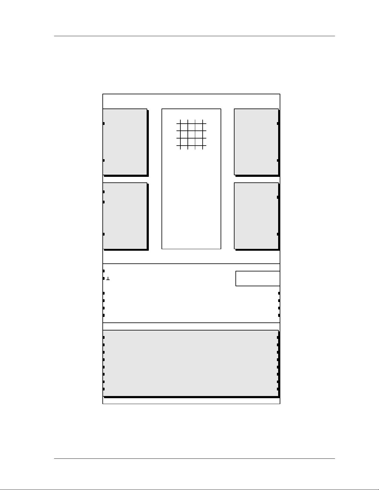
The following block diagram outlines the features once again. It shows a DPM 4000 equipped with a 2-channel paging
station module (NRS 90215), a MIC/LINE + 2 AUX inputs module (NRS 90216), two 2-channel LINE output modules
(NRS 90218) and an 8 I/O control module (NRS 90219). The ports of the interface block are standard. Their functioning
is explained in detail on the following pages. The "Optional" port allows for retrofitting an additional serial port for the
intercommunication between several DPM 4000s or connecting external devices / entire installations.
DPM 4000
IN A Pag. Console
SLOT 1
NRS 90215
IN B Pag. Console
AUX1
IN A
AUX2
SLOT 2
NRS 90216
IN B MIC / LINE
+
DC INPUT
24V =
RS-232 PC INTERFACE
DCF 77
INP 1
INP 2
AUDIO MATRIX 4x4
INPUT FILTERS
OUTPUT DELAYS
CHIME / ALARM
SIGNAL GENERATOR
MESSAGE RECORDER
SYSTEM TIMER
CALENDAR
CONTROL / SUPERVISION
POWER MANAGEMENT
INTERFACE
LINE OUT A
SLOT 3
NRS 90218
LINE OUT B
LINE OUT A
SLOT 4
NRS 90218
LINE OUT B
OPTION PORT
+ 24V =
READY
REMOTE CONTROL
MONITOR OUT
IN 1 SLAVE CLOCK OUT 1
IN 2 OUT 2
OUT 3
OUT 4
OUT 5
OUT 6
OUT 7
OUT 8
IN 3
IN 4
IN 5
IN 6
IN 7
IN 8
SLOT 5
NRS 90219
figure 5.1 DPM 4000 block diagram
PROANNOUNCE System User Handbook 1.1
5-2
Page 17
DEVICE DESCRIPTIONS
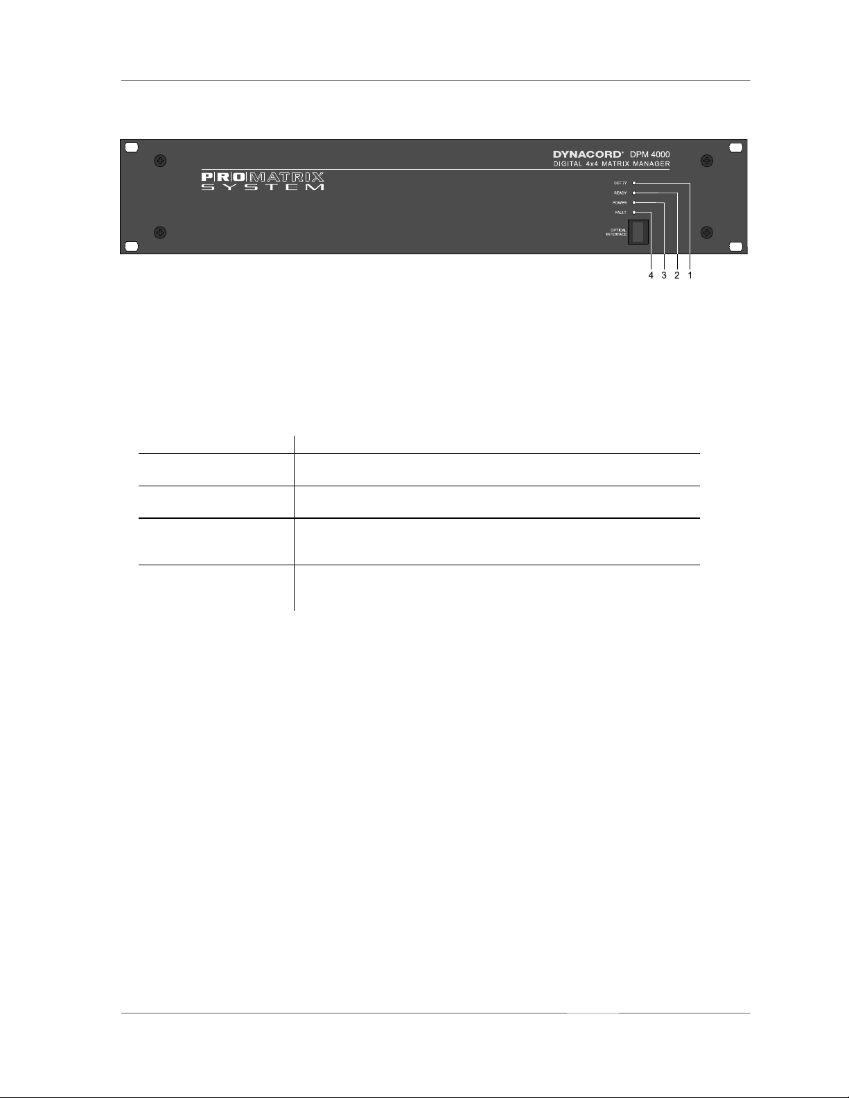
5.1.2 Front View
figure 5.2 DPM 4000 front view
The following controls and indicators are located on the DPM 4000's front panel:
1. LED DCF 77
This LED indicates the operation mode of the DCF 77 radio-controlled-signal receiver. The following table shows
the different indications and explains their corresponding status:
LED indication status
OFF
ON
Blinking, one cycle per
second
Blinking, fast
No radio control signal detected or no DCF 77 antenna connected. The
system clock is quartz-synchronized.
The radio control signal is received. The system clock is synchronized
to the DCF 77 signal.
The radio control signal is present and the system clock is being
synchronized. This procedure can take up to 2 minutes. After
synchronization is complete, the DCF 77 LED light continuously.
The radio control signal is detected but its reception is jammed. Readjusting the DCF 77 antenna or choosing a location with improved
reception is recommended.
2. LED READY
This LED indicates the operation mode of the PROANNOUNCE System. After switching the power on, the READY
LED blinks while the system boots. Depending on the complexity of the installation blinking can take several
seconds. After successful initialization, the LED lights, signaling that the system is ready for operation. Whenever
erroneous operation – either in the DPM 4000 or in one of the connected components – is detected, the LED goes
out indicating that a system error occurred. When the system power is OFF, the READY LED is OFF as well.
3. LED POWER
This LED lights as soon as a power source (24 V =, power supply or battery) is connected to the DPM 4000. The
LED does not light when the DPM 4000's power supply is disconnected, switched off or fails.
4. LED FAULT
This LED lights during a reset or when an internal watchdog error is being detected within the DPM 4000. It also
indicates erroneous operation of external system components (power amplifiers, paging stations, relay boards, ...).
The LED is connected to the READY relay on the rear of the appliance, which allows remote indication of system
errors.
PROANNOUNCE System User Handbook 1.1
5-3
Page 18
DEVICE DESCRIPTIONS
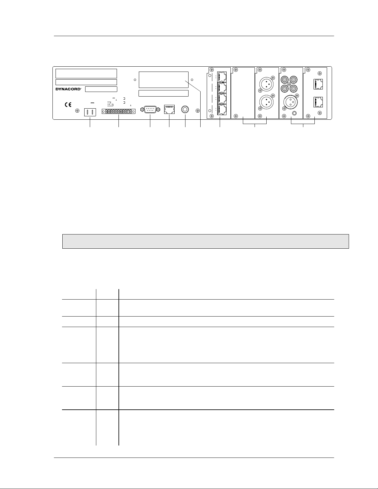
5.1.3 Rear View
TO REDUCE THE RISK OF FIRE OR ELECTRIC SHOCK,
WARN ING :
DO NOT EXPOSE THIS APPLIANCE TO RAIN OR MOISTURE.
RISQUÉ DE CHOC ELECTRIQUE. NE PAS OUVRIR.
AVI S :
NO USER SERVICEABLE PARTS INSIDE. REFER SERVICING TO
QUALIFIED SERVICE PERSONNEL.
DPM 4000
MADE IN GERMANY
121 619
DC INPUT
24
+--
SIGNAL INTERFACE
+ 24V
1
2
GROUND
3
READY
4
5
111
6
7
8
9
10
11
CAUTION:
FITTING AND CORRECT CABLES AND CONNECTION.
INP 1
INP 2
DCF 77
DCF 77 IN
PC INTERFACE
SEE OPERATION MANUAL FOR MODULE
RS-232
REMOTE
CONTROL
MONITOR OUT
8 OHMS 1 WATT
PHONES
5
C
O
N
T
R
O
L
OUT
IN
DPM - LC 8
8
5
NU41
8
5
4
1
4
90219
DPM - OUT
A
B
0/+6 dBu
0/+6 dBu
90218
LINE
OUT
LINE
OUT
A
LR
B
DPM - MLA
123
DPM - PCI
DPC 4000 IN
AUX
IN 1
A
AUX
IN 2
DPC 4000 IN
B
MIC/
LINE
IN
GAIN
90216
90215
1 2 3 4 5 7
6
89
figure 5.3 DPM 4000 rear view
The following module ports and connections are located on the rear panel of the DPM 4000:
1. DC INPUT 24V ==
The DPM 4000's power supply source has to be connected here; a 24 VDC power supply or a PROANNOUNCE
system battery module using insulated AMP flat-connector plugs 6.3 x 0.8 mm. The DPM 4000 is protected against
polarization mismatch and all positive and negative conductors within the device are fuse-protected. The fuses are
located inside the enclosure on the printed board assembly 80430. The connection cables have to be 1,5 mm
diameter at least. With this diameter the cable length of a single path should not exceed 4.0 m (max. drop in voltage
<1V).
CAUTION: Using the DPM 4000 is only permissible with batteries that are not grounded or provide a grounded
negative pole. Operation with grounded positive pole is not admissible.
2. SIGNAL INTERFACE
Signal Pins Description
+24V ==
1 24 V== voltage output for the supply of external components. The maximum current
handling capacity is 400 mA.
GROUND
READY
2 Ground connector of the 24 V== voltage output.
3, 4, 5 Floating output for the indication of the system's operation mode. In the normal ready
mode the READY relay is activated. When internal errors occur or external devices
show faulty behavior, the READY-relay drops. The relay is connected to the FAULT
LED indicator on the front panel of the DPM 4000 providing indication of the
operational status directly on the appliance.
INP1
6, 7 Floating input for monitoring / remote controlling the battery power supply, usually
connected to a battery module or battery charging unit. Since this input can be freely
programmed, using it for any other 24 V control signal is possible as well.
INP2
8, 9 Floating input for monitoring / remotely controlling the power supply, usually
connected to the 24 V== system power supply. Since this input can be freely
programmed, using it for any other 24 V control signal is possible as well.
DCF77
10, 11 Socket for connecting an external DCF 77 antenna. This input provides the supply
voltage and simultaneously serves as input for the decoded DCF 77 signal. Only
connecting the NRS 90193 DCF 77 receiver is admissible while polarity is not a
critical factor. However, according to CE regulations, shielded cabling has to be used.
Connect the shield to the connector's pin 10 and the signal line to pin 11.
2
in
PROANNOUNCE System User Handbook 1.1
5-4
Page 19
DEVICE DESCRIPTIONS
A
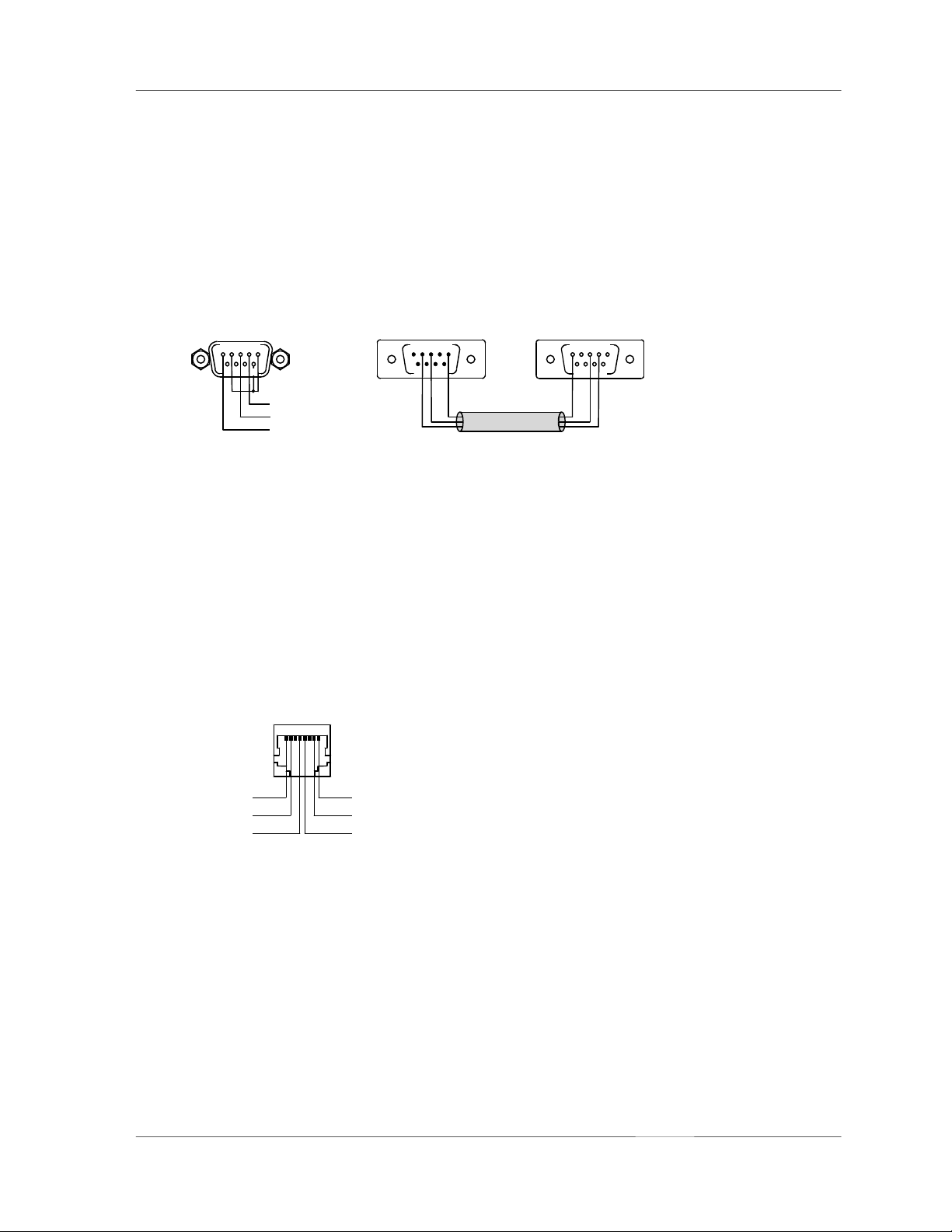
3. RS-232 PC INTERFACE
This 9-pole PC-interface is meant for connecting a computer (female, pin 4 = TXD, pin 3 = RXD, pin 1 = ground). It
is used to transfer data between the PC and the DPM 4000 during system configuration as well as for control,
monitoring, and remote diagnosis purposes. The PC is connected to the DPM 4000 utilizing a standard 1:1 D-sub
extension cord with male connectors on one end and female connectors on the other.
As an alternative to the RS-232 port, an optical IrDA interface is provided on the front panel of the appliance
offering the possibility for wireless data transmission.
RS-232
PC INTERFACE
12345
6
987
TxD
RxD
M
SSE
RS-232
54321
678
9 987
extension cord
12345
6
figure 5.4 pin-assignment of the RS-232 PC INTERFACE connector, D-Sub extension cord
4. REMOTE CONTROL socket
This 8-pole RJ-45-type socket is meant for connecting DCS 401 control modules or DPA 4000 power amplifiers with
remote interface. The connector provides a RS-485 interface for communicating with control modules and power
amplifiers (pins 4 / 5), a balanced audio input for the insertion of external monitor signals (pins 7 / 8), and a 24 V==
supply voltage output for the supply of external modules (pin 1 = +24 V, 1 A max., pin 2 = GND). A programmable
electronic fuse (adjustable to 330 mA, 660 mA, 990 mA) protects the voltage output against short-circuit and
overload. External devices are connected through common RJ-45 extension cords. For additional information,
please refer to the corresponding chapters of the individual device.
REMOTE
CONTROL
18
+ 24V
GND
RS-485 +
AUDIO IN AUDIO IN +
RS-485 -
figure 5.5 pin-assignment of the REMOTE CONTROL socket
The RS-485 bus may not exceed a maximum length of 1,000m and must follow a line-structure (short stub cables
are permissible). Cabling has to be carried out using twisted pair cables (38.400 Bd, 8N1)
PROANNOUNCE System User Handbook 1.1
5-5
Page 20
DEVICE DESCRIPTIONS
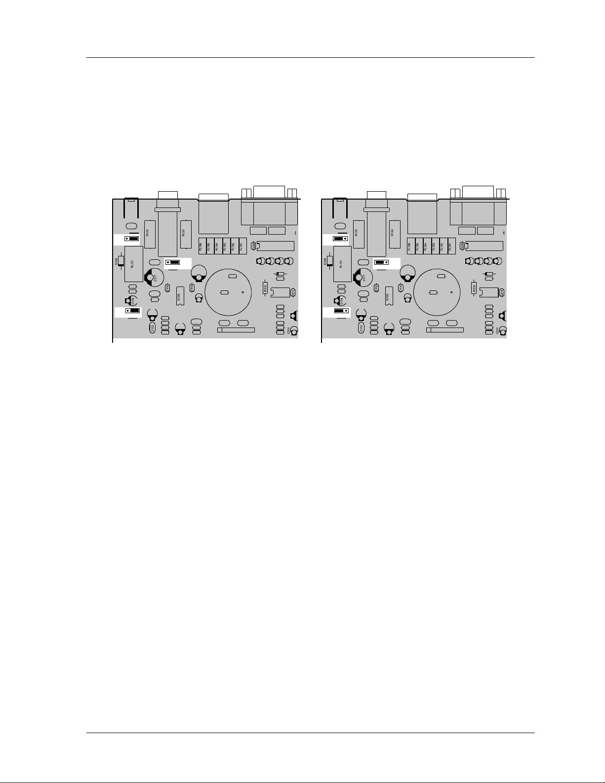
5. MONITOR OUTPUT socket
The audio signal of the integrated monitor amplifier is outputted via this connector. In standard configuration, this
output is set for the connection of headphones. It is also possible to directly connect a loudspeaker with minimum
load impedance of 8 Ohms. To achieve higher output capacity it is possible to set the internal monitor amplifier to
bridged operation. Thus some internal jumpers have to be re-set as shown in the figure below.
jumper-setting for headphones operation jumper-setting for bridged operation
Jumper-Einstellung für Kopfhörerbetrieb Jumper-Einstellung für Brückenbetrieb
JP101
JP102
C142
321
R122
R121
321
81
CN101
JS101
C141
C115
R120
C113
R118
R117
R110
R114
321
JP103
C139
C140
C108
C110
R107
R108
R101
R102
T101
C101 C102
RN101
CN201
FL201 FL202
IC201
C203 C201 C202 C204
IC204
96
51
D204
R211
R213
R212
R210
R216
R227
R228
JP101
JP102
C142
321
R122
R121
321
JS101
C141
321
C115
R120
C113
R118
R117
R110
R114
JP103
C110
81
CN101
C139
R102
C140
C108
C101 C102
R107
R108
T101
RN101
CN201
96
51
FL201 FL202
IC201
C203 C201 C202 C204
R101
D204
R211
IC204
R213
R212
R210
R216
R227
R228
figure 5.6 adjusting the monitor amplifier's output power via jumpers on the printed board assembly 80430
6. Extension slot
The DPM 4000 extension slot allows retrofitting additional serial ports, which can be used for the inter-
communication amongst DPM 4000 managers or to connect additional external devices. For detailed information,
please refer to the owner’s manuals of the individual extensions or modules.
7. Control Module Slot
Slot 5 is a control slot, which can be equipped with control modules for general control and query purposes. Control
modules provide different kinds of control inputs and outputs. For detailed description, please refer to the following
chapters. The DPM 4000 is shipped with one 8 I/O control module installed.
8. Slots for Audio Output Modules
The slots 3 and 4 are the DPM 4000's audio output slots providing two audio outputs per slot. Each slot can be
equipped with a 2-channel audio output module. The DPM 4000 is shipped with a 2-channel audio output module
installed in slot 3; described in detail at a later stage. Slot 4 is empty.
9. Audio Input Module Slots
The slots 1 and 2 are the DPM 4000's audio input module slots providing two audio inputs per slot. Each slot can be
equipped with any suitable audio input module. A detailed description of available audio input modules can be
found in the following chapters. The DPM 4000 is shipped with no audio input modules installed.
PROANNOUNCE System User Handbook 1.1
5-6
Page 21

DEVICE DESCRIPTIONS
5.1.4 Specifications
Supply voltage 24 V DC (21.6 ... 31.2 V DC)
Nominal power consumption 500 mA
Maximum power consumption 6.7 A
Audio section
Inputs see specifications of the corresponding input module
Outputs see specifications of the corresponding output module
Frequency Response 20 Hz ... 20 kHz, ± 0.5 dB
S/N ratio
Distortion
24 V output 24 V DC / 400 mA max. (21.6 ... 31.2 V DC)
Ready output floating relay contacts, 1 A / 24 V DC
Logic inputs 2, floating via opto-coupler, bi-pole
Voltage with input OFF (LOW) UIN < ± 5 V
Voltage with input ON (HIGH) UIN > ± 10 V
Maximum input voltage UIN max = ± 31 V
DCF77 input
RS-232 interface 19,200 Baud, 8 data bits, 1 stop bit, no parity, Xon/Xoff
Remote interface
Serial port RS-485 standard
Supply output short-circuit-proof, electronically programmable fuse
Monitor input electronically balanced, transformer optionally available
Max. input level +10 dBu / 2.5 V
Input balance > -30 dB
Monitor output 6.3 mm phone jack, either for the connection of headphones or speakers
Output level with headphones: 650 mV / -1.5 dBu
with loudspeakers: 1.8 V / 7.2 dBu
Output power handling with headphones: 50 mW / 8 W
with loudspeakers: 380 mW / 8 W
Operating temperature range +5 °C ... +40 °C
Dimensions W x H x D 19“, 2 HE 483 x 88 x 337 mm
Installation depth 340 mm (410 mm incl. connectors)
Weight 6.4 kg
Optionally available extensions NRS 90208 input transformer for 1 monitor input, order no. 121 641
> 100 dB (A-weighted)
< 0.01 %
2-pole, for the NRS 90193, DCF 77 receiver
Supply voltage 24 V DC (21.6 ... 31.2 V DC)
Nominal current 330 mA, 660 mA, 990 mA (selectable, electronic fuse)
Nominal input level +2.2 dBu / 1 V
PROANNOUNCE System User Handbook 1.1
5-7
Page 22
DEVICE DESCRIPTIONS
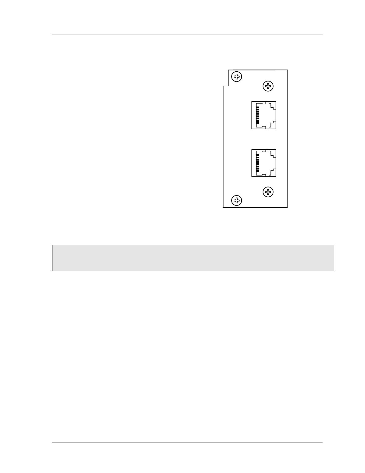
5.1.5 2-Channel Paging Station Module (NRS 90215)
This 2-channel audio input module is meant for the
connection of DPC 4000 Series paging consoles. Each of
the two input channels provide RJ-45 sockets allowing
the connection of up to 4 paging stations plus paging
station extensions per input. The microphone terminals
are interconnected via 6-conductor parallel cables. The
module can be installed in slot 1 and slot 2.
Next to the electronically balanced audio input, each input
connector provides a serial RS-485 interface port and the
power supply connection for the paging stations (see
also: pin-assignment of the RJ-45 connector). The paging
stations' power supply employs an electronic,
programmable fuse, through which the maximum output
current can be matched to meet actual system
accommodations. This prevents the entire installation
from malfunction, in case of short-circuit occurring in a
single paging station only.
Input channels can be switched separately onto the
monitor bus and you can monitor the audio signal via
headphones or loudspeaker, either which is connected to
the monitor output. Automatic pilot tone surveillance of
the entire input stage is integrated as well. If necessary,
retrofitting the audio inputs with transformers is possible.
figure 5.7 2-channel paging station module
DPM - PCI
DPC 4000 IN
A
DPC 4000 IN
B
90215
Note: When connecting several paging consoles to a single input, please keep in mind that line interruption or
short-circuit can cause malfunction of several or even all paging stations of that specific line. In
emergency alert installation, connecting security-related consoles to individual inputs is therefore of
major importance.
Specifications:
description DPM-PCI 2-channel paging station module, NRS 90215
connections
audio
inputs 2, electronically balanced, transformers are optionally available
input balancing
frequency response
S/N ratio
distortion
A/D-conversion
control interfaces 2 x RS-485 standard
power supply outputs for the DPC 4000 2, short-circuit-proof, electronically programmable fuses
power consumption 2 W
operational temperature range +5 °C ... +40 °C
dimensions W x H x D 37.5 x 81 x 248 mm
weight 152 g (220 g including 2 x NRS 90208)
extensions NRS 90208 input transformer for 1 paging station input, order-No. 121 641
2 x RJ-45 sockets
nominal input level 0 dBu / 775 mV
max. input level +12 dBu / 3 V
input impedance 20 kW
> -30 dB
20 Hz ... 20 kHz, ± 0.5 dB
> 100 dB (A-weighted)
< 0.01 %
18-bit linear, Sigma-Delta
supply voltage 24 V DC (21.6 ... 31.2 V DC)
nominal current 330 mA, 660 mA, 990 mA (adjustable, electronic fuse)
PROANNOUNCE System User Handbook 1.1
5-8
Page 23
DEVICE DESCRIPTIONS
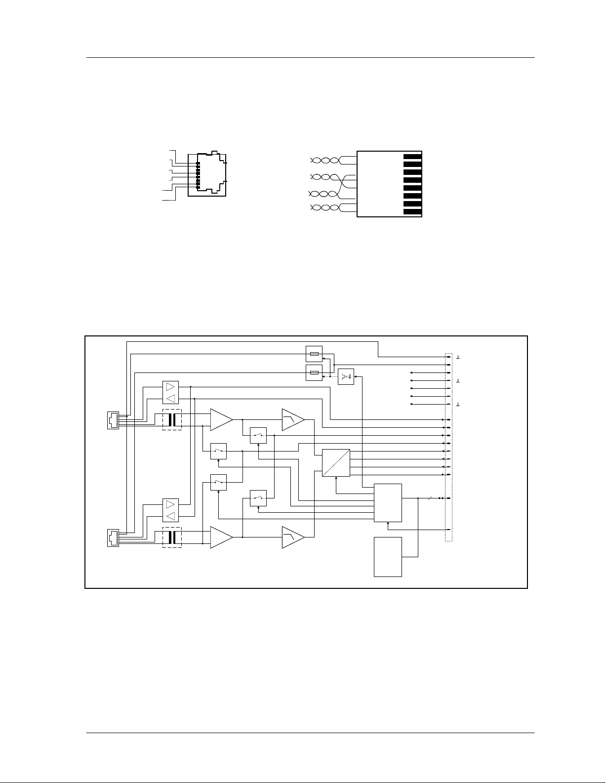
Pin-Assignment Of DPC 4000 Connectors And The Extension Cord:
Connecting DPC 4000 paging stations to the DPC 4000 IN connector is established through the use of common RJ-45
extension cords, where the conductors are twisted in pairs as follows: pair 1 = 1/2 (24 V/GND), pair 2 = 3/6 (free), pair
3 = 4/5 (RS-485), pair 4 = 7/8 (AUDIO).
AUDIO IN AUDIO IN +
RS-485 RS-485 +
GND
DPC 4000 IN
8
1
AUDIO
RS-485
+24V
24V/GND
figure 5.8 pin-assignment of the DPC 4000 connectors, RJ-45 extension cords
RJ-45 extensioncord
8
7
6
5
4
3
2
1
The RS-485 bus may not exceed a maximum length of 1,000m (mind the voltage drop for operation voltage) and must
follow a line-structure (short stub cables are permissible). Twisted-pair wiring is of special importance.
Using IY(ST)Y wiring is allowable (38400 Bd, 9N1)
Block Diagram:
ELECTRONIC
PROGRAMMABLE
FUSES
DPC 4000
IN A
24V
RS-485
AUDIO
RS-485
AUDIO
DPC 4000
24V
IN B
NRS 90208
MON A
PILOT A
PILOT B
MON B
NRS 90208
figure 5.9 block diagram 2-channel paging station module
+U24
+12V
ANALOG
SUPPLY
-12V
+5V
DIGITAL
SUPPLY
RX485
TX485
INTERNAL MONITOR
PILOT
A
D
BOARD
CONTROL
BOARD
STATUS
& ID
MCLK
2 CHANNEL
BCLK
DIGITAL
WCLK
AUDIO
DIN
4
SPI
RES
PROANNOUNCE System User Handbook 1.1
5-9
Page 24
DEVICE DESCRIPTIONS
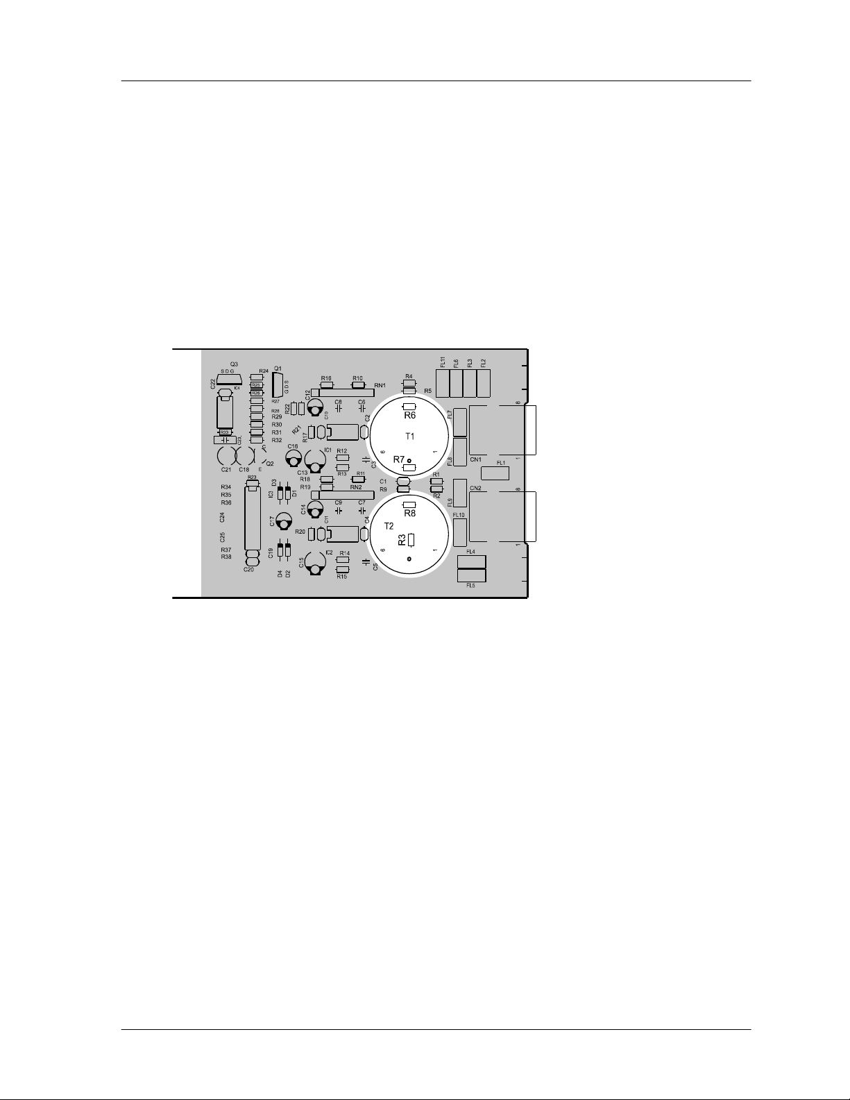
Retrofitting Input Transformers:
In case galvanic separation of the audio signal is necessary, the module is prepared for retrofitting two input
transformers. Separate NRS 90208 extensions consisting of audio transformer and insulation plate each are needed
per input channel.
When retrofitting the transformers, please proceed as follows:
1. Disconnect the DPM 4000 from the mains power supply.
2. Loosen the two locking screws and carefully slide the module out of the slot.
3. Remove the two resistors of the corresponding input channel (IN A: R6 / R7, IN B: R3 / R8).
4. Place the insulation plate between the transformer and the printed board assembly and solder the transformer to
position T1 for IN A or to position T2 for IN B.
5. Re-insert the module into the slot and carefully push it into the DPM 4000 until it firmly locks in place.
6. Fix the module in place using the two locking screws and reconnect the power supply.
figure 5.10 retrofitting the input transformers, location of parts (NRS 90215)
PROANNOUNCE System User Handbook 1.1
5-10
Page 25
DEVICE DESCRIPTIONS
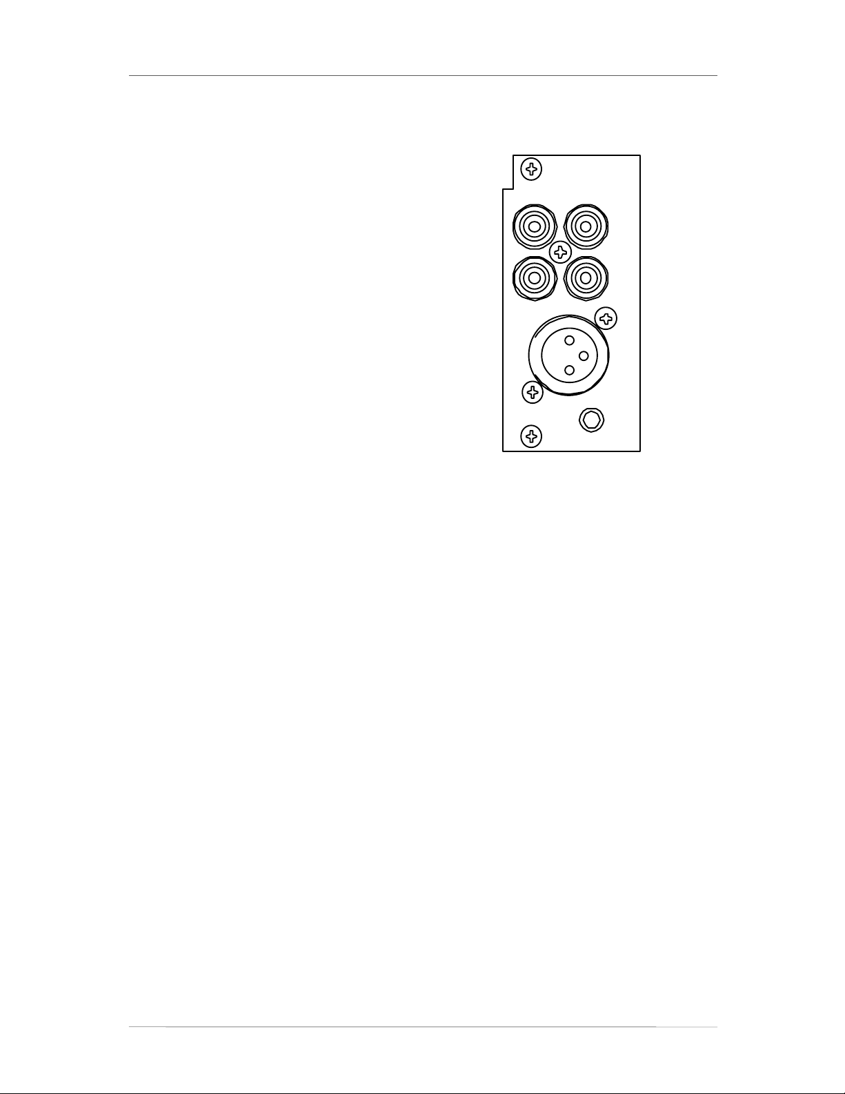
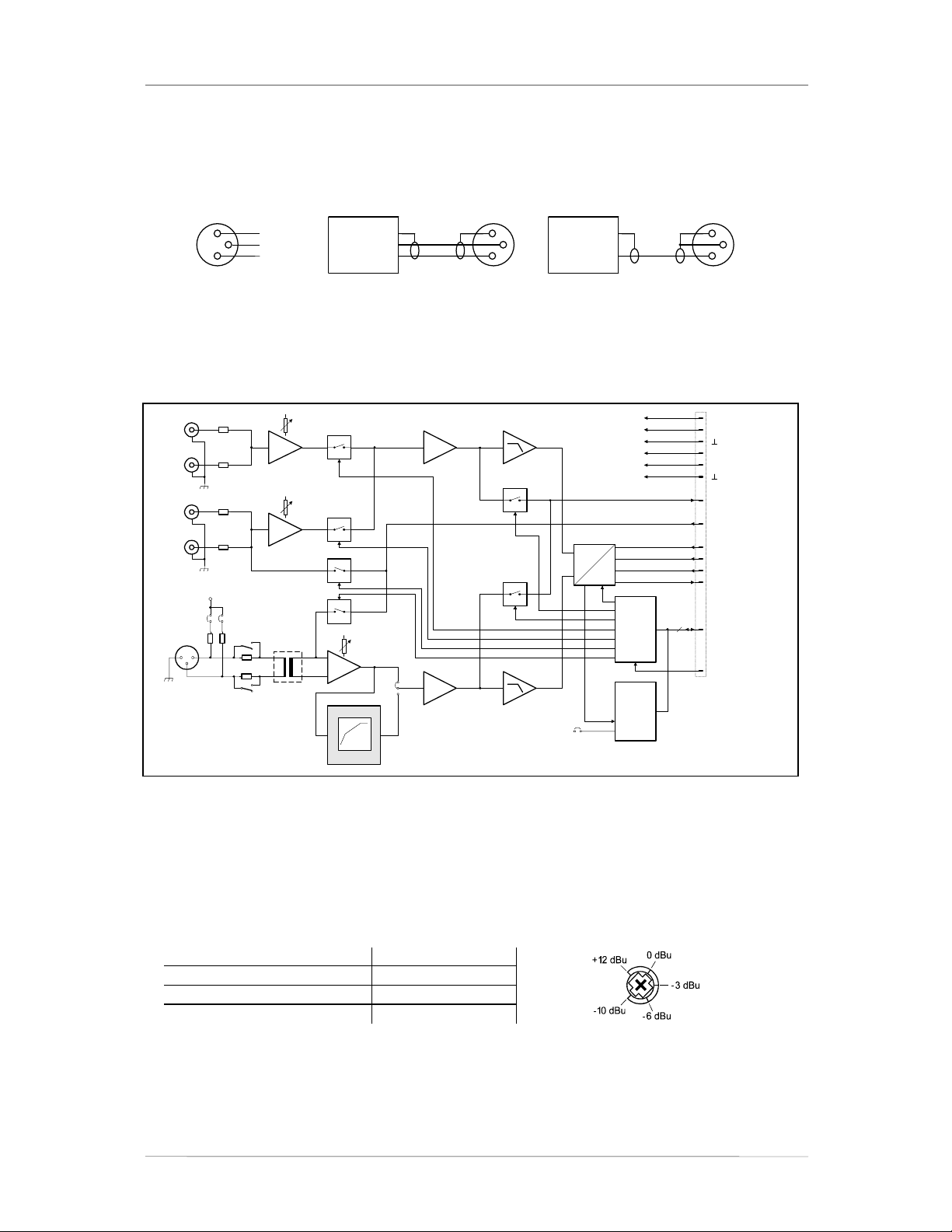
5.1.6 MIC/LINE + 2 AUX Input Module (NRS 90216)
This 2-channel audio input module is meant for the
connection of external audio sources of any kind.
Channel A employs two switched AUX-inputs with 4
RCA-type connectors (2 x L / R) for CD players, tape
decks, tuners, DAT decks, etc. The MIC / LINE-input of
channel B is provided through an XLRF-type connector
allowing the connection of microphones, mixers and other
similar sources. The module can be inserted in slot 1 and
slot 2.
Input levels of both AUX-inputs can be separately
adjusted via internal potentiometers in a range between –
10 dBu to +12 dBu.
The MIC / LINE-input's sensitivity can also be adjusted
through an internal MIC / LINE switch (PAD) providing 30
dB attenuation. The GAIN-control on the appliance's rear
panel offers additional control within a range of 40 dB.
The MIC / LINE input is electronically balanced and can
be retrofitted with a transformer. Phantom power can be
switched via a jumper. If necessary, it is also possible to
incorporate a compressor / limiter into the audio path via
jumper setting.
The input channels can be switched separately to the
monitor bus and you can listen to the signal via
figure 5.11 MIC/LINE + 2 AUX input module
headphones or loudspeaker, either which is being
connected to the monitor output. Automatic pilot tone
surveillance of the entire input stage is integrated as well.
Specifications:
description
connections 1 x XLRF-type / 4 x RCA-type connectors
input A
m
input B
LINE: -24 dBu ... +16 dBu / 50 mV ... 5 V
m
LINE: 10 kW
input balancing
audio
frequency response
S/N ratio
distortion
A/D-conversion 18-bit linear, Sigma-Delta
power consumption
operational temperature range
dimensions W x H x
weight
extensions
DPM-MLA MIC/LINE + 2 AUX input module, NRS 90216
2 x AUX, unbalanced, internally summed
nominal input level
ax. input level
input impedance
MIC/LINE, electronically balanced, transformers are optionally available
nominal input level
ax. input level
(im limiter operation)
input impedance
phantom power
> 95 dB (A-weighted)
< 0.01 %
160 g (173 g including NRS 90233)
NRS 90233 input transformer for 1 MIC/LINE input, order-No. 121 682
-10 dBu ... +12 dBu / 250 mV ... 3 V
+12 dBu / 3 V
10 kW
MIC: -54 dBu ... -14 dBu / 1.5 mV ... 155 mV
MIC: +5 dBu / 1.4 V
LINE: +30 dBu / 25 V
MIC: 3.6 kW
> -30 dB
24V / 20 mA, switched via jumper
20 Hz ... 20 kHz, ± 0.5 dB
2.3 W
+5 °C ... +40 °C
D 37.5 x 81 x 252 mm
DPM - MLA
A
LR
B
AUX
IN 1
AUX
IN 2
MIC/
LINE
IN
GAIN
90216
PROANNOUNCE System User Handbook 1.1
5-11
Page 26
DEVICE DESCRIPTIONS
Pin-Assignment Of XLRF-Type Connectors:
The pin-assignment of the MIC/LINE input's XLRF-type connector is as follows: pin 1 = screen, pin 2 = positive
conductor, pin 3 = negative conductor. In unbalanced configuration, the pins 3 (-) and 1 (screen) have to be
bridged inside the connection plug.
1
2
MIC/
LINE
IN
SHIELD
3
-+
BALANCED
SOURCE
LO (-)
HI (+)
1
2
3
UNBALANCED
SOURCE
1
3
2
figure 5.12 pin-assignment of the MIC/LINE IN XLRF-type connector
Block diagram:
4
+24V
+12V
ANALOG
SUPPLY
-12V
+5V
DIGITAL
SUPPLY
INTERNAL MONITOR
PILOT
MCLK
2 CHANNEL
BCLK
DIGITAL
WCLK
AUDIO
DIN
SPI
RES
IN A
IN B
AUX 1
AUX 2
MIC/
LINE
L
R
L
R
12
AUX 1
GAIN
AUX 1
AUX 2
GAIN
AUX 2
PILOT A
+24V
123
JP1
4
MIC
3
LINE
NRS 90233
PILOT B
GAIN
COMPRESSOR /
LIMITER
LIN
JP2
COMP
MON A
MON B
A
D
BOARD
CONTROL
BOARD
STATUS
JP1
LINE
MIC
5 6
& ID
figure 5.13 block diagram MIC/LINE + 2 AUX input module
Internal Settings:
1. AUX input sensitivity
The input levels can be set in a range of -10 dBu to +12 dBu using trimmers VR2 (AUX 1) and VR3 (AUX 2).
The trim-potentiometers’ coarse scales are meant for your convenience, helping you in adjusting the levels.
Potentiometer setting Input level
Left margin
Center position
Right margin
+12 dBu
-3 dBu
-10 dBu
2. MIC / LINE switching and sensitivity setting for the MIC / LINE input
The MIC / LINE input's internal PAD-switch (S1) allows switching the channels' sensitivity between
microphone and line level (30 dB). The GAIN-control on the module's front panel is provided to precisely
adjust the input sensitivity (range 40 dB).
PROANNOUNCE System User Handbook 1.1
5-12
Page 27

DEVICE DESCRIPTIONS
In addition, a MIC/LINE jumper (JP1, pins 5-6) is located on the printed board assembly, which allows
correctly configuring the input. When changing the MIC/LINE switch it is important to change the jumper
correspondingly (open = LINE, closed = MIC).
When shipped, the factory preset is: switch S1 in the LINE position and jumper JP1 open.
GAIN setting MIC / LINE setting MIC / LINE jumper Input level
Left margin
Center position
Right margin
MIC Closed -14 dBu
LINE Open +16 dBu
MIC Closed -28 dBu
LINE Open +2 dBu
MIC Closed -54 dBu
LINE Open -24 dBu
3. Phantom Power
By closing the jumper JP1, pins 1-2 and pins 3-4, engage 24 V phantom power is possible for microphones
that are directly connect. When shipped, the jumpers' factory preset position is “open” (no phantom power).
4. Compressor / Limiter
The MIC / LINE input channel embodies a compressor / limiter circuit which can be incorporated into the
signal path via jumper JP2 (position 1-2, COMP). Normally, the compressor / limiter should be used to
eliminate the risks of overdrive and clipping, when directly connecting a microphone. When shipped, the
jumper is set to its “Linear” position (2-3, LIN).
figure 5.14 retrofitting the input transformer, internal settings, location of parts (NRS 90216)
Retrofitting Input Transformers:
In case galvanic separation of the audio signal is necessary, an input transformer can be retrofitted to channel B
of the MIC / LINE module. This is accomplished using the extension kit NRS 90233.
When retrofitting input transformers, please proceed as follows:
1. Disconnect the DPM 4000 from the mains power supply.
2. Loosen the two locking screws and carefully slide the module out of the slot.
3. Remove the two resistors of input channel B (R7 / R11).
4. Solder the transformer in position T1 onto the printed board assembly.
5. Re-insert the module into the slot and carefully push it into the DPM 4000 until it firmly locks in place.
6. Fix the module in place using the two locking screws and reconnect the power supply.
PROANNOUNCE System User Handbook 1.1
5-13
Page 28

DEVICE DESCRIPTIONS
5.1.7 2-Channel MIC/LINE Input Module (NRS 90217)
This 2-channel audio input module is meant for the
connection of external audio sources, like microphones,
mixers, etc. Both channels are furnished with XLRF-type
connectors. The module can be installed into slot 1 and
slot 2.
The sensitivity of the MIC / LINE inputs can be adjusted
in a wide range. The internal MIC / LINE switches (PADs)
provide 30 dB attenuation. The separate GAIN-controls
for each channel provide additional control in a range of
40 dB. The MIC / LINE inputs are electronically balanced
and can be retrofitted with transformers. Phantom power
can be switched via jumper setting. If necessary,
compressors / limiters can also be incorporated in the
audio paths via jumpers.
Input channels can be switched separately onto the
monitor bus and you can listen to the signal via
headphones or loudspeaker, either which is being
connected to the monitor output. Automatic pilot tone
surveillance of the entire input stage is integrated as well.
figure 5.15 2-channel MIC/LINE input module
Specifications:
description
connections
audio
nominal input level MIC: -54 dBu ... -14 dBu / 1.5 mV ... 155 mV
LINE: -24 dBu ... +16 dBu / 50 mV ... 5 V
LINE: 10 kW
Input balancing
frequency response
S/N ratio
distortion
A/D-conversion
phantom power
power consumption
operational temperature range
dimensions W x H x
weight
extensions
DPM-MLI 2-channel MIC/LINE input module, NRS 90217
2 x XLRF-type connectors
inputs
max. input level
(in limiter operation)
input impedance
phantom power
2 x electronically balanced, transformers are optionally available
MIC: +5 dBu / 1.4 V
LINE: +30 dBu / 25 V
MIC: 3.6 kW
> -30 dB
24V / 20 mA, switched via jumper
20 Hz ... 20 kHz, ± 0.5 dB
> 95 dB (A-weighted)
< 0.01 %
18-bit linear, Sigma-Delta
24V / 20 mA, switched via jumper
3 W
+5 °C ... +40 °C
D 37.5 x 81 x 252 mm
160 g (186 g including 2 x NRS 90233)
NRS 90233 input transformer for 1 MIC/LINE input, order-No. 121 682
DPM - MLI
A
B
GAIN
MIC/
LINE
IN
MIC/
MIC/
LINE
LINE
IN
IN
GAIN
90217
PROANNOUNCE System User Handbook 1.1
5-14
Page 29

DEVICE DESCRIPTIONS
Pin-Assignment Of XLRF-Type Connectors:
The pin-assignment of the MIC/LINE input's XLRF-type connector is as follows: pin 1 = screen, pin 2 = positive
conductor, pin 3 = negative conductor. In unbalanced configuration, the pins 3 (-) and 1 (screen) have to be
bridged inside the connection plug.
1
2
MIC/
LINE
IN
SHIELD
3
-+
BALANCED
SOURCE
LO (-)
HI (+)
1
2
3
UNBALANCED
SOURCE
1
3
2
figure 5.16 pin-assignment of the MIC/LINE IN XLRF-type connectors
Block diagram:
+24V
123
JP1
12
3
12
3
4
MIC
LINE
NRS 90233
+24V
123
JP2
4
MIC
LINE
NRS 90233
COMPRESSOR /
LIMITER
PILOT A
PILOT B
COMPRESSOR /
LIMITER
GAIN A
GAIN B
LIN
JP3
COMP
MON A
A
D
MON B
LIN
JP4
COMP
MIC / LINE A
MIC / LINE B
JP1
5 6
5 6
JP2
BOARD
CONTROL
BOARD
STATUS
& ID
MIC/
LINE
IN A
MIC/
LINE
IN B
4
+24V
+12V
ANALOG
SUPPLY
-12V
+5V
DIGITAL
SUPPLY
PILOT
INTERNAL MONITOR
MCLK
2 CHANNEL
BCLK
DIGITAL
WCLK
AUDIO
DIN
SPI
RES
figure 5.17 block diagram of the 2-channel MIC/LINE input module
Internal Settings:
1. MIC / LINE switching and sensitivity setting for the MIC / LINE inputs
The MIC / LINE input's internal PAD-switches (IN A: S1, IN B: S2) allow switching the channels' sensitivity
between microphone and line level (30 dB). The two GAIN-controls on the module's front panel are provided
to precisely adjust the input sensitivity (range 40 dB).
In addition, two MIC/LINE jumpers (IN A: JP1, pins 5-6, IN B: JP2, pins 5-6) are located on the printed board
assembly allowing the correct configuration of the inputs. When changing a MIC/LINE switch it is important to
change the related jumper correspondingly (open = LINE, closed = MIC).
When shipped, the factory presets are: switches S1 and S2 set to LINE and jumpers JP1 and JP2 are open.
GAIN setting MIC / LINE setting MIC / LINE jumper Input level
Left margin
Center position
Right margin
MIC Closed -14 dBu
LINE Open +16 dBu
MIC Closed -28 dBu
LINE Open +2 dBu
MIC Closed -54 dBu
LINE Open -24 dBu
PROANNOUNCE System User Handbook 1.1
5-15
Page 30

DEVICE DESCRIPTIONS
2. Phantom Power
By closing the jumpers JP1, pins 1-2 and pins 3-4 (IN A) respectively JP2, pins 1-2 and pins 3-4 (IN B), it is
possible to (separately) engage 24 V phantom power when a microphone is connected to the corresponding
input. When shipped, jumpers are set to “open” (no phantom power).
3. Compressor / Limiter
The MIC / LINE input channels embody compressor / limiter circuits, which can be incorporated in the signal
paths via the jumpers JP3 for IN A and JP4 for IN B (position “COMP”), if needed. Normally, the compressors /
limiters should be used to eliminate the risks of overdrive and clipping, when directly connecting microphones.
When shipped, the jumpers are set to “LIN”.
figure 5.18 retrofitting the input transformers, internal settings, location of parts (NRS 90217)
Retrofitting Input Transformers:
In case galvanic separation of the audio signals is necessary, the module can be retrofitted with two input
transformers. This is accomplished by using an extension kit NRS 90233 per input channel.
When retrofitting input transformers, please proceed as follows:
1. Disconnect the DPM 4000 from the mains power supply.
2. Loosen the two locking screws and carefully slide the module out of the slot..
3. Remove the two resistors of the correspondent input channel (IN A: R2 / R3, IN B: R10 / R11).
4. Solder the transformer for IN A in position T1 and for IN B in position T2 onto the printed board assembly.
5. Re-insert the module into the slot and carefully push it into the DPM 4000 until it firmly locks in place.
6. Fix the module in place using the two locking screws and reconnect the power supply.
PROANNOUNCE System User Handbook 1.1
5-16
Page 31

DEVICE DESCRIPTIONS
5.1.8 2-Channel AUX Input Module (NRS 90228)
This 2-channel audio input module provides 8 RCA-type
connectors (4 x L / R) for connecting external audio
sources such as CD-players, tape decks, tuners, DAT
decks, etc. The module can be installed into slot 1 and
slot 2.
The input levels of the four AUX inputs can be
independently adjusted in a range between -10 dBu and
+12 dBu via internal trim-potentiometers.
Input channels can be switched separately to the monitor
bus and you can listen to the signal via headphones or
loudspeaker, either which being connected to the monitor
output. Automatic pilot tone surveillance of the entire
input stage is integrated as well.
DPM - AUX
AUX
IN 1
A
AUX
IN 2
LR
AUX
IN 3
B
AUX
IN 4
Specifications:
description
connections
audio
m
input impedance 10 kW
frequency response
S/N ratio
distortion
A/D-conversion
power consumption
operational temperature range
dimensions W x H x D
weight
DPM-AUX 2-channel AUX input module, NRS 90228
8 x RCA-type connectors
inputs
4 x AUX, unbalanced, internally summed
nominal input level
ax. input level
> 100 dB (A-weighted)
< 0.01 %
150 g
-10 dBu ... +12 dBu / 250 mV ... 3 V
+12 dBu / 3 V
20 Hz ... 20 kHz, ± 0.5 dB
18-bit linear, Sigma-Delta
1.4 W
+5 °C ... +40 °C
37.5 x 81 x 252 mm
figure 5.19 2-channel AUX input module
90 22 8
PROANNOUNCE System User Handbook 1.1
5-17
Page 32

DEVICE DESCRIPTIONS
Block Diagram:
4
+24V
+12V
ANALOG
SUPPLY
-12V
+5V
DIGITAL
SUPPLY
INTERNAL MONITOR
PILOT
MCLK
2 CHANNEL
BCLK
DIGITAL
WCLK
AUDIO
DIN
SPI
RES
AUX 1
L
AUX 1
R
IN A
L
AUX 2
R
L
AUX 3
R
IN B
L
AUX 4
R
GAIN
AUX 2
GAIN
AUX 3
GAIN
AUX 4
GAIN
AUX 1
MON A
AUX 2
PILOT A
MON B
PILOT B
AUX 3
AUX 4
figure 5.20 block diagram 2-channel AUX input module
A
D
BOARD
CONTROL
BOARD
STATUS
& ID
Internal Settings:
AUX input sensitivity setting
Using trimmers VR1 (AUX 1), VR2 (AUX 2), VR3 (AUX 3) and VR4 (AUX 4), adjusting input levels is possible
in a range between -10 dBu and +12 dBu. The trim-potentiometers' coarse scales are meant for your
convenience, helping you in adjusting the levels.
Potentiometer setting Input level
Left margin
Center position
right margin
+12 dBu
-3 dBu
-10 dBu
figure 5.21 internal settings, location of parts (NRS 90228)
PROANNOUNCE System User Handbook 1.1
5-18
Page 33

DEVICE DESCRIPTIONS
5.1.9 MIC/LINE + Paging Station Module (NRS 90234)
This 2-channel audio input module is meant for the
connection of DPC 4000 Series paging stations and other
external audio sources. The RJ-45 socket of channel A
allows the connection of up to 4 microphone terminals
plus paging station extensions. The MIC / LINE input of
channel B is furnished through an XLRF-type connector
allowing the connection of microphones, mixers and other
audio signal sources. The module can be installed into
slot 1 and slot 2.
Next to the electronically balanced audio input, the DPC
4000 input connector provides a serial RS-485 interface
and the power supply for the connected paging consoles
(see also pin-assignment of the RJ-45 connector). The
paging stations' power supply employs an electronic,
programmable fuse, through which the maximum output
current can be matched to meet actual system
accommodations.
The MIC / LINE input employs an internal switch (PAD)
providing 30 dB of attenuation. The GAIN-control located
on the appliance's rear panel offers additional control in a
range of 40 dB. The input is electronically balanced and
prepared for retrofitting a transformer. Phantom power
can be switched via jumper. If necessary, a compressor /
limiter circuit can be incorporated in the audio path.
Input channels can be switched separately to the monitor
bus and you can listen to the signal via headphones or
loudspeaker, either which being connected to the monitor
output. Automatic pilot tone surveillance of the entire
input stage is integrated as well.
Note:
When connecting several paging consoles to a single input, please keep in mind that line
interruption or short-circuit can cause malfunction of several or even all paging stations of that
specific line. In emergency alert installation, connecting security-related consoles to individual
inputs is therefore of major importance.
Specifications:
description
connections
input A
input B MIC/LINE, electronically balanced, transformers are optionally available
LINE: -24 dBu ... +16 dBu / 50 mV ... 5 V
m
LINE: 10 kW
audio
input balancing > -30 dB
frequency response
S/N ratio
distortion
A/D-conversion
control interface
DPM-MLC MIC/LINE + paging station module, NRS 90234
1 x RJ-45 socket; 1 x XLRF-type connector
DPC 4000, electronically balanced, transformers are optionally available
nominal input level
max. input level
input impedance
nominal input level
ax. input level
(in limiter operation)
input impedance
Phantom power
> 95 dB (A-weighted)
< 0.01 %
0 dBu / 775 mV
+12 dBu / 3 V
20 kW
MIC: -54 dBu ... -14 dBu / 1.5 mV ... 155 mV
MIC: +5 dBu / 1.4 V
LINE: +30 dBu / 25 V
MIC: 3.6 k
24V / 20 mA, switched via jumper
20 Hz ... 20 kHz, ± 0.5 dB
18-bit linear, Sigma-Delta
1 x RS-485 standard
figure 5.22 MIC/LINE + paging station module (NRS 90234)
W
PROANNOUNCE System User Handbook 1.1
5-19
Page 34

DEVICE DESCRIPTIONS
A
A
A
supply output for the DPC 4000
supply voltage
nominal current 330 mA, 660 mA, 990 mA (set via electronic fuse)
power consumption
operational temperature range
dimensions W x H x D
weight
165 g (215 g including NRS 90208 + NRS 90233)
extensions
NRS 90208 input transformer for 1 paging station input, order No. 121 641
24 V DC (21.6 ... 31.2 V DC)
2.5 W
37.5 x 81 x 252 mm
1, short-circuit-proof, electronic, programmable fuse
+5 °C ... +40 °C
NRS 90233 input transformer for 1 MIC/LINE input, order No. 121 682
Pin-Assignment Of RJ-45 Socket And Extension Cord:
Connecting DPC 4000 paging stations to the DPC 4000 IN connector is performed using common RJ-45
extension cords, where the conductors are twisted in pairs as follows: pair 1 = 1/2 (24 V/GND), pair 2 = 3/6 (free),
pair 3 = 4/5 (RS-485), pair 4 = 7/8 (AUDIO).
UDIO IN UDIO IN +
RS-485 RS- 485 +
GND
DPC 4000 IN
8
1
UDIO
RS- 485
+24V
24V/GND
figure 5.23 pin-assignment of the DPC 4000 socket, RJ-45 extension cord
RJ-45 extensioncord
8
7
6
5
4
3
2
1
The RS-485 bus may not exceed a maximum length of 1,000m (mind the voltage drop for operation voltage) and
must follow a line-structure (short stub cables are permissible). Twisted-pair wiring is of special importance.
Using IY(ST)Y wiring is allowable (38400 Bd, 9N1)
Pin-Assignment Of XLRF-Type Connectors:
The pin-assignment of the MIC/LINE input's XLRF-type connector is as follows: pin 1 = screen, pin 2 = positive
conductor, pin 3 = negative conductor. In unbalanced configuration, the pins 3 (-) and 1 (screen) have to be
bridged inside the connection plug.
1
2
MIC/
LINE
IN
figure 5.24 pin-assignment of the MIC/LINE IN XLRF-type connector
SHIELD
3
-+
BALANCED
SOURCE
LO (-)
HI (+)
1
2
3
UNBALANCED
SOURCE
1
3
2
PROANNOUNCE System User Handbook 1.1
5-20
Page 35

DEVICE DESCRIPTIONS
Block Diagram:
ELECTRONIC
PROGRAMMABLE
FUSE
DPC 4000
IN A
24V
RS-485
AUDIO
+24V
123
JP1
12
3
4
MIC/
LINE
IN B
NRS 90208
PILOT A
MIC
LINE
NRS 90233
PILOT B
GAIN
COMPRESSOR /
LIMITER
MON A
A
D
MON B
BOARD
CONTROL
LIN
JP2
COMP
JP1
LINE
MIC
5 6
BOARD
STATUS
& ID
4
+U24
+12V
ANALOG
SUPPLY
-12V
+5V
DIGITAL
SUPPLY
RX485
TX485
INTERNAL MONITOR
PILOT
MCLK
2 CHANNEL
BCLK
DIGITAL
WCLK
AUDIO
DIN
SPI
RES
figure 5.25 block diagram MIC/LINE + paging station module
Internal Settings:
1. MIC / LINE switching and sensitivity of the MIC / LINE input
The MIC / LINE input's internal PAD-switch (S1) allows switching the channels' sensitivity between
microphone and line levels (30 dB). The GAIN-control on the module's front panel is provided to precisely
adjust the input sensitivity (range 40 dB).
In addition, a MIC/LINE jumper (JP1, pins 5-6) is located on the printed board assembly, which allows
correctly configuring the input. It is important to change the jumper accordingly (open = LINE, closed = MIC)
when changing the MIC/LINE switch.
When shipped the switch S1 is pre-set to LINE and the jumper JP1 to its open position.
GAIN setting MIC / LINE setting MIC / LINE jumper Input level
Left margin
Center position
Right margin
MIC Closed -14 dBu
LINE Open +16 dBu
MIC Closed -28 dBu
LINE Open +2 dBu
MIC Closed -54 dBu
LINE Open -24 dBu
2. Phantom power
Closing the pins 1-2 and 3-4 of the jumper JP1 offers the possibility to engage 24 V phantom power for
microphones that are connected directly. When shipped, the jumper is factory pre-set to its “open” position (no
phantom power).
3. Compressor / Limiter
The MIC / LINE input channel embodies a compressor / limiter circuit which can be incorporated into the
signal path via jumper JP2 (position COMP). Normally, the compressor / limiter should be used to eliminate
the risks of overdrive and clipping, when directly connecting a microphone. When shipped, the jumper is preset to its “Linear” position (LIN).
PROANNOUNCE System User Handbook 1.1
5-21
Page 36

DEVICE DESCRIPTIONS
Retrofitting Input Transformers:
Retrofitting two input transformers onto the module is possible for the case that galvanic separation of the audio
signals is needed. For the DPC 4000 input a NRS 90208 extension is needed, which consists of an audio
transformer and an insulation plate. For the MIC/LINE input a NRS 90233 extension is needed.
When retrofitting input transformers, please proceed as follows:
1. Disconnect the DPM 4000 from the mains power supply.
2. Loosen the two locking screws and carefully slide the module out of its slot.
3. Remove the two resistors of the corresponding input channel (IN A: R8 / R9, IN B: R3 / R4).
4. With the DPC 4000 input (IN A), you have to place the insulation plate between the transformer and the
printed board assembly. Then solder the transformer in position T2; with the MIC/LINE input (IN B), you have
to solder the transformer in position T1.
5. Re-insert the module into the slot and carefully push it into the DPM 4000 until it firmly locks in place.
6. Fix the module in place using the two locking screws and reconnect the power supply.
figure 5.26 retrofitting the input transformers, internal settings, location of parts (NRS 90234)
PROANNOUNCE System User Handbook 1.1
5-22
Page 37

DEVICE DESCRIPTIONS
5.1.10 2-Channel LINE Output Module (NRS 90218)
The output module is meant for the connection of power
amplifiers with an input sensitivity of 0 dB or +6 dB. Two
XLRM-type connectors allow the connection of up to 20
power amplifiers each. The audio signal is electronically
balanced; if necessary, transformers can be retrofitted.
The module can be installed in slot 3 or slot 4.
The output channels can be switched separately to the
monitor bus and you can listen to the signal via
headphones or loudspeaker, either which is connected to
the monitor output. Automatic pilot tone surveillance of
the two output channels is also integrated. The jumpers
for adjusting the output voltage to 0 dB or +6 dB are
located on the printed board assembly. At the same time
you have to alter the jumper setting of the monitor signal
correspondingly.
The output module employs integrated output relays that
prevent switching noise from being heard. When
switching the system on, the output signal is put through
after the system is been initialized (power-on delay); the
contacts are immediately interrupted when switching the
power off.
figure 5.27 2-channel LINE output module
Specifications:
description
connections
audio
nominal output level 0 dBu / 775 mV or +6 dBu / 1.55 V, switched via jumper
frequency response
dynamic range
S/N ratio > 109 dB (A-weighted)
distortion
D/A-conversion
power consumption
operational temperature range +5 °C ... +40 °C
dimensions W x H x D
weight
extensions
DPM-OUT 2-channel LINE output module, NRS 90218
2 x XLRM-type connectors
outputs
output impedance
2, electronically balanced, transformers are optionally available
115 W
20 Hz ... 20 kHz, ± 0.5 dB
> 97 dB (A-weighted)
£ 0.005 %
20-bit linear, Sigma-Delta
1.5 W
37.5 x 81 x 247 mm
160 g (255 g including 2 x NRS 90227)
NRS 90227 output transformer for 1 output order-No. 121 679
A
B
DPM - OUT
LINE
OUT
0/+ 6 dB u
LINE
OUT
0/+ 6 dB u
90218
PROANNOUNCE System User Handbook 1.1
5-23
Page 38

DEVICE DESCRIPTIONS
Pin-Assignment Of XLRM-Type Connectors:
The LINE output XLR-connectors' pin-assignment is as follows: pin 1 = screen, Pin 2 = positive conductor, pin 3 =
negative conductor. In unbalanced configuration the pins 3 (-) and 1 (screen) have to be bridged inside the
connected plug.
figure 5.28 pin-assignment of the OUT XLR-connectors
Block diagram:
+U24
ANALOG
SUPPLY
DIGITAL
SUPPLY
2 CHANNEL
DIGITAL
AUDIO
+12V
-12V
+5V
INTERNAL
MONITOR
MCLK
BCLK
WCLK
DOUT
RES
R3
NRS 90227
0dB+6dB
JP1.A
0dB
+6dB
D
A
BOARD
4
SPI
CONTROL
JP2.A
0dB+6dB
JP1.B
0dB
+6dB
JP2.B
MON A
MON B
R2
MUTE A
R5
NRS 90227
R4
MUTE B
12
OUT A
3
12
OUT B
3
BOARD
ID
figure 5.29 block diagram of the 2-channel LINE output module
Setting Output Levels Via Jumpers:
Each of the two outputs' output level can be set to 0 dB or +6 dB using the jumpers JP1 and JP2. Please make
sure to set both jumpers of an output channel (A / B) to the desired position.
When shipped, the output levels for both output channels are factory pre-set to 0 dB (all jumpers are closed).
Jumper setting
JP1, 2-4 / JP2, 2-4
Open
Closed
Output level
Jumper setting
channel A
+6 dB
0 dB
JP1, 1-3 / JP2, 1-3
Open
Closed
Output level
channel B
+6 dB
0 dB
Jumper setting for the output assignment: To be used in network installations.
When used in a network environment, the following jumpers have to be open:
OUT A LK10, LK11
(applies to printed board assemblies starting with index C!)
OUT B LK 8, LK 9
PROANNOUNCE System User Handbook 1.1
5-24
Page 39

DEVICE DESCRIPTIONS
Retrofitting Output Transformers:
Retrofitting two output transformers onto the module is possible for the case that galvanic separation of the audio
signals is needed. Therefore, separate NRS 90227 extensions are needed per output channel.
When retrofitting output transformers, please proceed as follows:
1. Disconnect the DPM 4000 from the mains power supply.
2. Loosen the two locking screws and carefully slide the module out of its slot.
3. Remove the two resistors of the correspondent output channel (OUT A: R2 / R3, OUT B: R4 / R5).
4. Close the two bridges of the correspondent output channel (OUT A: LK1 / LK2, OUT B: LK3 / LK4). The
soldering pads on the printed board assembly have to be short-circuited (closed).
5. Solder the transformer onto the printed board assembly: for OUT A in position T1 and for OUT B in T2.
6. Re-insert the module into the slot and carefully push it into the DPM 4000 until it firmly locks in place.
7. Fix the module in place using the two locking screws and reconnect the mains power supply.
figure 5.30 output level jumpers, retrofitting transformers, location of parts (NRS 90218)
PROANNOUNCE System User Handbook 1.1
5-25
Page 40

DEVICE DESCRIPTIONS
5.1.11 8 I/O Control Module (NRS 90219)
This control module provides 8 floating control inputs and
7 floating logic level outputs (0 V, 24 V). An additional
output provides pole change impulses for controlling
slave system clocks. Contact is established via 4 x RJ-45
sockets providing 8 contacts each. The module can be
installed in slot 5.
The slave clock output (NU, OUT 1) is short-circuit proof;
up to approximately 40 slave clocks can be connected.
Please make sure to connect all slave clocks according to
their correct polarity.
The control outputs (OUT 2 - 8) are capable of switching
voltages of either polarity and up to a maximum current of
1 A.
The control inputs (IN 1 - 8) are capable of handling
voltages of either polarity between -31 V and +31 V; for
voltages between 0 and 5 V the inputs are not active
(low), for voltages between 10 V and 31 V the inputs are
active (high). The control inputs can ignite switching
functions or macros either during a change of state or in
any stationary state. This offers the possibility to monitor
line idling currents (e. g. in fire alert system installations).
Note:
The opto-coupler inputs are primarily meant to prevent noise loops that can result from dropping
voltages in long distance cabling. They are not suitable for separating networks from each other.
Therefore, only floating sources should be connected.
Specifications:
description
connections
logic inputs
logic outputs 7, floating via relay contacts
slave clock output
output voltage
maximum output current
power consumption 3.2 W (12 W with the maximum amount of slave clocks connected)
operational temperature range
dimensions W x H x D
weight
DPM-LC8 8 I/O control module, NRS 90219
4 x RJ-45 sockets
8, floating via opto-coupler, bi-polar
voltage when the input is LOW
voltage when the input is HIGH
maximum input voltage
contact capacity
195 g
1 A / 24 V DC
pole change impulse / turning impulse
24 V DC
500 mA, electronically protected against overload
+5 °C ... +40 °C
37.5 x 81 x 247 mm
IN
U
U
< ± 5 V
IN
> ± 10 V
IN max
U
= ± 31 V
figure 5.31 8 I/O control module
PROANNOUNCE System User Handbook 1.1
5-26
Page 41

DEVICE DESCRIPTIONS
Pin-Assignment Of RJ-45 Connectors:
The floating control inputs and outputs provide 2 adjacent contacts, each. The following diagram shows the
assignment of RJ-45 contacts to inputs / outputs.
slave clocks
figure 5.32 pin-assignment of the IN / OUT connectors
Block diagram:
IN1
IN2
IN3
SLAVE
CLOCK
OUT2
OUT3
OUT4
OUT5
OUT6
OUT7
OUT8
IN4
IN5
IN6
IN7
IN8
INPUT
REGISTER
OUTPUT
REGISTER
figure 5.33 block diagram of the 8 I/O control module
BOARD
CONTROL
BOARD
STATUS
& ID
+U24
+5V
DIGITAL
SUPPLY
DATA BUS
D8 - D15
CONTROL
4
SPI
RES
PROANNOUNCE System User Handbook 1.1
5-27
Page 42

DEVICE DESCRIPTIONS
5.1.12 Flash Memory for Voice Recording/Playback (NRS 90205)
Internal Message Recorder
For using the internal message memory at least one voice message module NRS 90205 (121648) needs to be
installed in the DPM 4000 and the SW-Message (121709) needs to be enabled. Up to maximally 4 memory
modules can be retrofitted. The memory modules need to be formatted before the first use.
The Message Stacking Function is available together with the recorder.
Data:
- number of internal texts (messages) 25
- sampling frequency 48kHz
- sampling format 16-bit linear at a bandwidth of 20kHz
8-bit compressed at a bandwidth of 10kHz
- maximum recording time 16-bit, 20kHz, 1 message memory: 22,5 sec.
16-bit, 20kHz, 4 message memory: 90 sec.
8-bit, 10kHz, 1 message memory: 90 sec. (1,5 min.)
8Bit, 10kHz, 4 message memory: 360 sec. (6 min.)
- signal sources DPM 4000 inputs IN1 – IN4
Instructions for retrofitting the Message Memory Extension (NRS 90205) into the DPM 4000
contents: 1 printed board assembly 86237
1 manual
1. Disconnect the appliance from any power supply.
2. Remove the cover (7 screws).
3. Insert the printed board 86237 on the main pcb 80249C
4. Format the inserted memory boards (only possible using the PROANNOUNCE Designer software).
- Insert the printed board 86237 into an empty slot, starting with CN301, CN302, CN303 or CN 304.
PROANNOUNCE System User Handbook 1.1
5-28
Page 43

DEVICE DESCRIPTIONS
5.2 PROANNOUNCE – DPC 4000 Paging Consoles
5.2.1 System Overview
The PROANNOUNCE system includes 5 different models of DPC 4000 Series paging stations and one paging
station extension. All microphone terminals employ gooseneck microphones, 6 or 8 function keys and a covered
alarm key. An additional alarm key and a key-locked switch can be retrofitted. The paging stations are available
with 10, 20, 30, or 50 selection keys. All models also employ LC-displays (2 lines with 16 characters each).
The following list provides you with an overview of available paging station models:
DPC 4510 8 function keys + 10 selection keys + alarm key
All paging consoles include the following common features:
All paging consoles are processor-controlled and extensive monitoring functions are provided. The watchdog
function monitors the processor system while a switchable pilot tone generator monitors the audio section.
Additionally, the internal supply voltage is constantly measured. When it falls below a critical threshold an alert
message is being displayed. The line surveillance function recognizes any line-interruption and/or short-circuits in
the audio and RS-485 control cabling. Upon the detection of failure a corresponding message is displayed.
The PROANNOUNCE Designer software allows comfortably configuring the paging stations. Its graphic,
dialogue-oriented user interface offers effortless assign of key functions, priorities, options, and many other
paging station functions.
DPC 4106
DPC 4520
DPC 4530
DPC 4550
DPC 4350
all functions are processor-controlled
·
configuration data is stored in non-volatile FLASH RAM
·
condenser microphone with pre-amplifier and compressor / limiter circuitry
·
freely programmable key-assignment
·
easy key-labeling through label-strips and MS WORD™ templates
·
analog circuitry surveillance via integrated pilot tone generator
·
processor surveillance via watchdog function
·
line surveillance via pilot tone and polling functions
·
covered alarm key (not with DPC 4106)
·
additional alarm keys or key-locked switches can be optionally retrofitted
·
connection of an external PTT-microphone or audio source
·
piezo buzzer for acoustical alerts
·
an optional loudspeaker can be retrofitted
·
setup-mode allows direct parameter setting at the paging station
·
two-line LC-display
·
Note: Up to four paging consoles can be connected to a single input of the central unit. However, it
6 function keys
8 function keys + 20 selection keys + alarm key
8 function keys + 30 selection keys + alarm key
8 function keys + 50 selection keys + alarm key
paging console extension with 50 selection keys
is important to keep the fact in mind that in case of line interruption and short-circuit several
microphone terminals may fail. Despite, one input allows only launching one message at a
time. All other connected paging stations are presented with a busy-message. If these
restrictions are not acceptable, every microphone terminal – or at least all directing stations
and other important paging stations – should have its own input at the central unit.
PROANNOUNCE System User Handbook 1.1
5-29
Page 44

DEVICE DESCRIPTIONS
g
p
g
p
g
g
r
g
g
5.2.2 Paging Console Functions
Next to elementary messaging, the paging stations offer several additional functions, which in summation are
shown in the following diagram. Which functions a microphone terminal can initiate depends on its configuration
and priority setting.
Table of all functions
announcement
start
si
nal
selective
call
collective
call
direkt
call
gong
text
general
alarm
selective
ala
m
lines
roups
all
stop
si
nal
clear
selection
power
on / off
program
assi
nment
lines
roups, all
assi
clear
nment
special
functions
start
macro
paging station
setu
address
assword
Pre-gong
buzzer
compressor
date / time
LCD-contrast
service
functions
figure 5.34 overview of possible paging console functions
Detailed information on the different functions is provided within the following chapters of this handbook.
5-30 PROANNOUNCE System User Handbook 1.1
Page 45

DEVICE DESCRIPTIONS
5.2.3 Control Panel Of The DPC 4550
11
12
1
11 12
21 22
31 32
41 42 43
3
4
5
6
7
2
13
14
15
16
23
24
25
26
33
34
35
36
44
45
46
1
8
17
18
27
28
37
38
47
48
10
9
19
20
29
30
39
40
49
LÖSCHEN
50
ALLE
2
EIN
GONG
3456
ALARM
DPC 4550
PROGRAMMSTOPP
BUSYESC
TEXT SPRECHEN
figure 5.35 control panel of the DPC 4550
1 Selection Keys and LED’s
Depending on the individual paging station model, 10, 20, 30, or 50 selection keys with corresponding LED’s
are provided. The selection keys are used to pre-select areas or groups for the reproduction of messages,
gong or alarm signals, vocal messages, or to assign programs (pressed once = ON, subsequently pressed =
OFF). The LED’s indicate the momentary selection status (also refer to the paragraph “indications”). It is also
possible to assign special functions or no function at all (no function assigned) to the selection keys. Assigning
functions is performed during the configuration procedure via PC.
Note:
When shipped, these keys are factory pre-set as area selection keys, where key 1 –
area 1, key 2 – area 2, ..., key n – area n.
10
13
7
8
9
2 ALL key and LED
The ALL key allows the selection of all programmed areas at once for transmitting messages, gong or alarm
signals, vocal messages, or to assign programs. One time pressing selects all areas. The corresponding
LED’s and the ALL LED are lit. Subsequent pressing cancels the selection.
3 CANCEL key
This key offers different functions, depending on the actually selected operation mode, e.g. cancel calling
pattern or cancel program-assignment. Which function is carried out at times is explained in detail in the
paragraph OPERATION.
4 GONG key (ESC) and LED
Pressing this key starts the transmission of a gong signal in the pre-selected areas or groups. The GONG LED
lights or blinks during the transmission of a gong signal. What kind of gong signal is being transmitted is
defined during the configuration procedure. Pressing the STOP key cancels the reproduction of the gong
signal.
While in setup-mode, this key is used to return to ‘normal’ user mode (ESCAPE = leaving setup-mode).
PROANNOUNCE System User Handbook 1.1
5-31
Page 46

DEVICE DESCRIPTIONS
5 TEXT key (Ú) and LED
Pressing the TEXT key starts a prerecorded message (optional voice reproduction), which is transmitted into
pre-selected areas or groups. The TEXT LED lights or blinks during the transmission of a prerecorded
message. The desired text message is selected during the configuration procedure. Pressing the STOP key
cancels the reproduction of a text message.
While in setup-mode, pressing the TEXT key decreases the selected parameter value (parameter entry).
6 TALK key and BUSY-LED
This key activates a message for pre-selected areas or groups. The BUSY LED lights during transmission.
The TALK key has to be pressed until the end of a message. The BUSY LED blinks when one or several
areas are busy or when an event with higher priority setting interrupts the output message (see paragraph
indications). In the latter, it is necessary to repeat the message.
7 ON key (<) and LED
This key turns the system’s power on or off. Turning the power on can take several seconds. The ON LED
blinks while the system boots. The ON LED lights steadily when the system is operational. To prevent
inadvertent erroneous operation pressing the key for at least 1 second is necessary when turning the power
off. It is also possible to prohibit the operation of the ON key during the configuration procedure.
In setup-mode this key is used to select the previous parameter (parameter selection).
8 STOP key (Ù)
Pressing the STOP key cancels an output alarm signal or text message. Terminating an alarm signal is also
possible by subsequently pressing the ALARM key. Only events that were triggered from a specific paging
console can be stopped from the exact terminal with the exception of the directing station. This terminal allows
canceling all signals.
While in setup-mode, this key increases the selected parameter value (parameter entry).
9 PROGRAM key (>) and LED
Pressing the PROGRAM key selects the program assign mode. The selection keys are used in this mode to
assign a program (background music) to the desired areas or groups. The PROGRAM LED lights while being
in the program assign mode. In this case the selection LED’s indicate the areas / groups the program is being
transmitted into.
Keeping this key pressed and simultaneously pressing the STOP key selects the setup-mode and the
PROGRAM LED starts blinking. Now you can alter preferences or make other changes as described in the
chapter 5.2.7 Paging Station Configuration In Setup Mode.
When in setup-mode, this key is used to select the following parameter (parameter selection).
10 ALARM key and Indicator
Pressing the ALARM key starts an alarm signal that is transmitted into all areas. The alarm indicator lights
when launching an alarm. Pressing the STOP key or subsequently pressing the ALARM key terminates the
alarm signal. What kind of alarm signal is being transmitted is defined during the configuration procedure of
the PROANNOUNCE system.
11 Optional Key-Slots
These slots allow retrofitting an additional covered key and a key-locked switch. The front panel is already
prepared for the installation of two 18 mm pushbuttons / switches. You only have to cut suitable holes into the
front panel foil. Internal fittings and cables are also already prepared. The newly installed switches’ functions
are assigned during the configuration procedure via PC; e.g.: second alarm-pushbutton for transmitting an
alarm signal into specific areas (selective alarm), or assigning the system ON / OFF function to the key-locked
switch.
Detailed information and installation instructions are provided in the chapter 5.2.13 Optionally Available
Accessories.
5-32 PROANNOUNCE System User Handbook 1.1
Page 47

DEVICE DESCRIPTIONS
12 Microphone
After pressing the TALK button and after the BUSY LED lights making announcements in pre-selected areas
or groups is possible using the integrated gooseneck microphone. The optimum distance from the microphone
is approximately 20 to 35 cm. The microphone pre-amplifier embodies a limiter to control signal peaks and
protect the system against overdrive.
The extension socket (EXT) allows connecting a second microphone with TALK button. Assigning the function
(area, group) of the external microphone is performed during the configuration via PC.
13 Display
Depending on the actual operational status of the system, the LC-display with 2 lines of 16 characters each,
shows information on time, operation mode, user notes, setting up, fault messages including precise device /
module specification, etc.
5.2.4 Connections
1 LAN socket
This is the interface for connecting DPC 4000 Series paging stations to the PROANNOUNCE system. The 8pole RJ-45 connector provides power supply, control interface RS-485, and audio connections. The
microphone terminal has to be connected to a corresponding RJ-45 wall outlet using the supplied connection
cord (3 m). The following figure shows the pin-assignment of LAN socket and RJ-45 network cable. Please
also pay attention to chapter 5.2.14 Cable Lengths.
figure 5.36 LAN socket and RJ-45 network cable pin-assignment
2 EXT socket
Mostly, this socket is used for connecting a DPC4350 paging station extension. Use the supplied network
cable (0.5 m) to connect the DPC4350 to the paging console’s EXT socket.
In case no paging station extension is being connected, utilizing the EXT socket for connecting a second
microphone with TALK button or other external audio signal sources to the paging console is possible as well.
Detailed information is provided in chapter 5.2.13 Optionally Available Accessories.
figure 5.37 EXT socket pin-assignment
PROANNOUNCE System User Handbook 1.1
5-33
Page 48

DEVICE DESCRIPTIONS
5.2.5 Key-Labeling
Labeling the keys of paging consoles is done using label-strips, which can be slid in from the side. The label-strips
for the 6 or 8 function keys are slid in from the right while the selection key strips – for 10, 20, 30, or 50 selection
keys – are inserted from left. Therefore, you have to detach the correspondent side panel (2 screws) and insert
the labeled strip into the gap between the front panel and the front panel foil.
The most convenient way of printing the labels is to utilize the word processing software MS-WORD. A suitable
MS-WORD template file is supplied. Please note that with different printer models margin-settings may vary.
Please adjust the layout form according to the individual specifications of your printer model.
Tested printer models are:
HP LaserJet 5
HP LaserJet II
The recommended paper thickness is between 120 g/m
Also supplied with this handbook are prepared label-strips in German, English and French as well as empty strips
which only have to be cut out. You can label the empty strips in handwriting or by using Letraset
HP LaserJet 6P
2
and 200 g/m2.
®
letters.
5-34 PROANNOUNCE System User Handbook 1.1
Page 49

DEVICE DESCRIPTIONS
5.2.6 Operation
This chapter explains all functions that are used during general operation.
Selective Call
The user can launch calls or announcements into freely selectable areas or groups.
Pressing a single or several selection keys defines areas or groups where a call is launched into – corresponding
LED’s will light. By pressing the key of an already pre-selected line once again deactivates that line and the
corresponding LED goes out.
After making a selection, pressing the TALK-button ignites the call. Prior hereto, the BUSY LED allows checking
whether all lines and the paging station input are actually free. If single lines or the terminal input are busy with
lower priority transmissions, the BUSY LED will blink slowly. Whilst making an announcement is possible, this will
interrupt any other transmitted event. If single lines or the terminal input are busy with higher priority signals, the
BUSY LED will vastly blink and the calling attempt is ignored (also refer to the description of indications).
The BUSY LED lights during the transmission of an announcement. The TALK button has to be pressed during
the whole message. Until the user makes any changes, the defined selection stays memorized, even after
releasing the TALK button. Pressing the CANCEL key de-selects the entire selection.
Additionally and in case of a pre-gong signal has previously been programmed, the GONG LED will light during
the transmission of the pre-gong signal.
Collective Call
The announcement is launched into all areas of the entire installation.
The procedure is similar to making a selective call. First, all areas of the installation are selected by pressing the
ALL key. Pressing the TALK button activates the collective call. During the transmission of a call, all area and/or
group LED’s as well as the ALL LED will light (also refer to the paragraph “indications”). The TALK button has to
be pressed down until the end of the announcement. BUSY LED indication and the behavior of the pre-gong
signal are equivalent to the selective call.
Direct Call
Principally, assigning a direct call to any selection key (area key, group key, ALL key) is possible via PC during
the configuration procedure. This allows making an announcement directly by pressing the desired selection key
– without need to press the TALK key. For direct calls the BUSY LED also signals the status of correspondent
areas (free, busy with lower priority signal, busy with higher priority signal; see “indications”). When shipped, there
is no factory pre-set direct call programmed.
Gong (Chime) Signal
By factory the Gong key is programmed as a general call
A gong signal can also be transmitted into any selectable area or group of the entire installation (if programmed).
First, the desired areas / groups have to be selected; either by use of the selection keys (selective gong) or with
the ALL key (general gong). Pressing the GONG key releases the gong signal. While the gong signal is being
transmitted, the GONG LED lights continuously or blinks (also refer to indications). The gong’s priority can be set
to 6 or 7. Therefore it has priority over announcements from any paging station, except for the directing terminal
(priority 10).
Pressing the STOP key cancels the transmission of a gong signal.
During setup mode this key is used to go back to the normal operating mode (escape).
PROANNOUNCE System User Handbook 1.1
5-35
Page 50

DEVICE DESCRIPTIONS
Text Message
A text message recorded via the optional message module or using an external recording/playback device can be
transmitted into any selectable area or group of the entire installation.
First, the desired areas / groups have to be selected; either by use of the selection keys or via the ALL key.
Pressing the TEXT key starts the reproduction of a prerecorded message that had been assigned during
configuration. While the text message is being transmitted, the TEXT LED lights steadily or blinks (also refer to
indications). The text message priority can be set to values between 2 and 8.
Pressing the STOP key cancels the transmission of a text message.
General Alarm
A general alarm signal is always transmitted to all lines of the entire installation.
Pressing the covered ALARM key launches the integrated alarm. The key lights during the transmission of the
alarm signal. The priority of the alarm can be set between 7 and 9. Therefore it has priority over any
announcement or other event, except for those that were ignited from the directing paging station (priority 10).
Pressing the STOP key or subsequently pressing the ALARM key cancels the alarm.
Selective Alarm
When a paging station is equipped with a second ALARM key providing the option for selective alarms, it is
possible to transmit alarm signals into selected lines.
Similar to the procedure for making a selective call you first have to select areas or groups to which the alarm
signal shall be transmitted. Afterwards, pressing the covered ALARM key starts the selective alarm. The key lights
during the transmission of an alarm. Already now, you are able to enter the lines for the following alarm.
Pressing the STOP key or subsequently pressing the ALARM key cancels the alarm.
When shipped, there is no factory pre-set selective alarm pre-programmed.
Note:
The launch of an alarm does not depend on a paging console’s priority setting it had been
activated from. Launching an alarm is possible from any microphone terminal at any time,
even when the system is in stand-by mode. A running alarm is optically and occasionally also
acoustically indicated at every paging station.
Canceling Signals
Pressing the STOP key cancels alarms, gong signals and text message transmissions. Events can only be
terminated at the paging station they were launched from with the exception of the directing terminal (paging
console with the highest priority possible 10). Through the directing station it is possible to cancel any signal in
progress.
5-36 PROANNOUNCE System User Handbook 1.1
Page 51

DEVICE DESCRIPTIONS
System ON / OFF
The ON key switches a PROANNOUNCE system ON or OFF. Mostly, it is not intended that any paging station be
provided with the possibility to do so. Thus, this function can be programmed via PC-configuration.
When the system is in stand-by mode, the ON LED is off. Pressing the ON key turns the PROANNOUNCE
system’s power on which can take up to 10 seconds, while the ON LED is blinking. Once the system is ready for
operation, the ON LED lights continuously (which also applies for all paging stations of the entire installation).
To switch the system OFF, you have to press the ON key for approximately 1 second. This is to prevent
inadvertently turning off the system.
Pressing an ALARM key or igniting an alarm sequence at external terminals automatically switches the
PROANNOUNCE system’s power on and boots the system.
Program Assignment
Activating this feature allows the assignment of programs to individual areas and groups of the entire installation
during the PC-configuration procedure.
First, by pressing the PROGRAM key, the paging station has to be set to program-assign mode. Pressing a single
or several selection keys assigns the outputted program (background music) to the selected areas and groups.
The corresponding LED’s are lit. Program transmission has always the lowest priority (1). The signal level is
determined during system configuration. The assignment stays memorized until the selection keys are pressed
again. Pressing the CANCEL key erases the entire assignment-pattern.
Subsequently pressing the PROGRAM key or any other function key cancels program-assign mode. It is also
automatically canceled after approximately 15 seconds.
In single-program configuration the music reproduction into all areas of the installation is attenuated for the time of
an announcement. In double-program configuration parallel transmission of a background music program into
rooms that are not part of an actual announcement selection is possible as well. If every line incorporates its own
LF-output and separate power amplifiers, mixing announcements and background programs is possible in any
way.
Special Functions
Generally, assigning a function to each selection key is possible. This allows utilizing a paging station to control
the lighting, door openers, blinds, etc.; even controlling volume settings is possible through the use of the UP /
DOWN keys.
When shipped, there are no special functions assigned.
PROANNOUNCE System User Handbook 1.1
5-37
Page 52

DEVICE DESCRIPTIONS
5.2.7 Paging Console Configuration In Setup Mode
Configuring paging consoles is preferably performed on the central unit via computer and using the
PROANNOUNCE Designer software. This represents the most convenient way without any limitation, while a
paging terminal itself offers only limited programming ability.
Several key functions differ between setup-mode and operation mode. Alternate functions are marked on the right
top corner of the individual key area.
Pressing PROGRAM key and STOP key simultaneously for at least 1 second – the PROGRAM LED starts
blinking – engages a paging station’s setup-mode.
Note:
Paging stations where program-assignment has been activated indicate the program
assignment-pattern for a short period of time.
Using the ‘<‘ and ‘>‘ keys lets you step through the setup menu items in forward and backward direction
(parameter selection). Parameter number and name are shown on the display.
The following table shows an overview of parameters and their meaning:
Parameter
number
1 Address
2 Password
3 Pre-gong signal
4 Buzzer
5 Compressor
6 Date / Time
7 LCD contrast
The ‘Ù‘ and ‘Ú‘ keys activate / deactivate corresponding parameters or increment / decrement according
parameter values. For directly entering numerical parameters, use selection keys 1 to 10, where the 10-key
represents the “0”.
Pressing the ESC key returns to ‘normal’ operation. The setup-mode is also automatically canceled when for
approximately 15 seconds no entry or change has been made. All parameters are automatically stored.
1 Address
Paging consoles accept the assignment of addresses between 1 and 16. The setting is generally performed
using the numerical keys 1 to 10, where the 10-key represents the “0”. For paging stations without selection
keys, the address has to be set using the ‘Ù‘ und ‘Ú‘ keys.
CAUTION: When shipped all paging station addresses are set to OFF (no address). Therefore it
When applying operation voltage for the first time, paging consoles start up in entry
Parameter name Description
Paging station address-assignment (addresses 1 - 16)
Unwanted access protection in two levels via code numbers:
- 3-digit = normal operation
- 4-digit = setup-mode
Message pre-gong ON / OFF
Acoustic signal (buzzer) on failure or as alert and during an outgoing alarm
signal
Microphone pre-amplifier compressor ON / OFF
Entry of date and time in the formats:
tt.mm.yy hh:mm
Setting the LCD-contrast and/or view angle
is important to assign a correct address to a microphone terminal, before the first
operation. Within an installation terminal addresses have to be assigned exclusively;
a specific address can exist only once!
mode right away.
5-38 PROANNOUNCE System User Handbook 1.1
Page 53

DEVICE DESCRIPTIONS
2 Password
(does not apply to paging consoles without selection keys)
3 or 4-digit passwords provide protection for paging consoles against unauthorized operation. Password
protection can be established in two levels. The first level is the ‘normal’ user-level. In case this level is
password-protected, the paging station cannot be operated except for launching an alarm. The second level is
the setup-level. If this level is password-protected, the setup-mode is not accessible while unlimited ‘normal’
operation is possible.
Level 1 and 2 passwords are assigned and transferred to the individual paging stations during the PCconfiguration procedure. As factory preset the level 1 password is set to ‘111’ and the level 2 password is
‘2222’; level 2 (setup-mode) is password-protected (factory pre-set).
To prevent a paging station from unwanted access, you have to enter setup-mode and select parameter 2
“password”. Depending on which function of the paging console you want to protect, by using the selection
keys you have to enter either the 3-digit level 1 password or the 4-digit level 2 password. Protection is now
activated and operation (1st level) and/or programming (2nd level) are not possible anymore. The blinking
PROGRAM LED indicates this status.
The protection is canceled by re-entering the correct password while being in setup-mode.
3 Pre-Gong Signal
It is possible to program a pre-gong signal that is heard before an announcement. The pre-gong signal is
transmitted into the selected areas when pressing the TALK-button. You can begin with your announcement
during the transmission of the pre-gong signal; you can talk “into” the pre-gong.
Using the arrow keys (<>) first select parameter 3. Now, you can ignite the pre-gong signal with the ‘Ù‘ key or
cancel it by using the ‘Ú‘ key. The pre-gong function can also be activated or deactivated during PCconfiguration.
4 Buzzer
The integrated buzzer can be programmed as acoustic alert signal. During failure, malfunction, or as general
alert a buzzing sound is heard. When an alarm has been launched, the buzzing can be heard for the whole
period of the alarm.
First, select parameter 4 using the arrow keys (<>). Now, you can activate the buzzer by pressing the ‘Ù‘ key.
Pressing the ‘Ú‘ key deactivates the buzzer. The buzzer function can also be activated during PCconfiguration.
5 Compressor
The paging stations’ microphone pre-amplifier incorporates compressor / limiter circuitry. While the limiter is
constantly activated, the compressor can be switched ON or OFF. When the compressor is engaged, lowlevel signals are amplified to a higher degree, which results in constant talking levels although the distance
between the announcer and the microphone varies. Besides, you have to keep in mind that also
environmental noise is amplified. Thus, on-site testing with and without compressor will reveal which results in
the better performance.
First, by using the arrow keys (<>), select parameter 5. Pressing the ‘Ù‘ key activates the compressor.
Pressing the ‘Ú‘ key deactivates the compressor. It is also possible to activate the compressor during the PCconfiguration procedure.
6 Time / Date
(does not apply to paging consoles without selection keys)
The connected paging stations allow setting the date and time of the PROANNOUNCE system.
First, by using the arrow keys (<>), select parameter 6. Using the selection keys 1 to 10 – with the 10-key
representing the “0” – you can enter the correct time. Date and time are indicated in the following format:
tt.mm.yy hh:mm. They have to be entered in that sequence
7 LCD-Contrast
Paging consoles with display allow the user to individually adjust LCD-contrast and viewing angle. This allows
optimum legibility from the user’s location.
First, by using the arrow keys (<>), select parameter 7. Now, you can adjust the LCD-contrast via the ‘Ù‘ or ‘Ú‘
keys.
PROANNOUNCE System User Handbook 1.1
5-39
Page 54

DEVICE DESCRIPTIONS
5.2.8 Indications
The following table provides you with an overview of the most important LED-indications.
LED Status Description
Selection LED OFF No group or area selected
(not with DPC 4106) Lights green Area or group selected / special function activated / direct call
ALLE LED OFF No collective call selected
(not with DPC 4106) Lights green Collective call pre-selected / direct collective call activated
BUSY LED OFF System not busy, clear for call
Lights green During own message
Slow blinking, green Low priority paging station launches a call in selected areas;
Fast blinking, green System is busy with a higher priority transmission (message,
GONG LED OFF No gong signal started
Lights green Gong signal in progress; manually started or pre-
Lights green Gong signal in progress, ignited from another source or time-
ON LED OFF System is OFF (stand-by mode)
Lights green System is ON and ready for operation
Blinks green System has been turned on and is booting (initialization)
PROGRAMM LED OFF Paging console is in message-mode
Lights green Paging console is in program assign mode
Slow blinking, green Paging console is password-protected
Fast blinking, green Paging console is in setup-mode
TEXT LED OFF No text message launched
Lights green Text message in progress, manually launched
Blinks green Text message in progress, launched from another source or
ALARM OFF No alarm signal launched
Lights red Alarm signal has been launched from any source
Blinks red Alarm signal has already been stopped, but keeps running
activated
interruption on cost of the momentary microphone terminal is
possible
gong, alarm), interruption is not possible, already launched
call is interrupted by events with higher priority setting
programmed pre-gong signal
controlled
time-controlled
until signal-end
5-40 PROANNOUNCE System User Handbook 1.1
Page 55

DEVICE DESCRIPTIONS
5.2.9 Priorities
The PROANNOUNCE system allows setting 10 priority levels (highest priority = 10, lowest priority = 1) that
include announcements, as well as alarm and gong signals, and vocal message reproduction. A higher prioritized
event principally interrupts any other event with a lower priority setting. For events with equal priority the earlier
launched signal is continued; has priority over the latter.
Priority level Assigned Description
10
7 - 9
6 - 7
2 - 8
2 - 6
1
Directing station Highest priority; can ignite any type of events and interrupt
Alarm signal Can only be interrupted from the directing station; but
Gong signal
(manual / time-controlled)
Recorded message These priorities can be freely assigned to text messages
Message from a paging
console without / with pre-
gong signal
Program Background music always has the lowest priority level.
all other signals.
interrupts all other signals that have not been launched from
the directing terminal.
Interrupts all signals that are not coming from the directing
terminal. Time-controlled gong signals can be delayed/predelayed by a pre-defined period of time.
during the configuration procedure.
These priorities can be freely assigned to any ‘normal’
paging console. A pre-gong signal has the priority of the
launching microphone terminal.
5.2.10 DPC 4350 Paging Station Extension
The DPC 4350 paging station extension provides selection keys only. It is employed whenever a higher amount
than 50 lines need to be accessed or when an installation’s requirement of group and special function keys
exceeds the existing amount of selection keys. The DPC 4350 can be easily combined with any other paging
station model. The following list shows the amounts of maximally accessible lines for various combinations:
Combination Maximum amount of lines
DPC 4106 + DPC 4350 50
DPC 4510 + DPC 4350 60
DPC 4520 + DPC 4350 70
DPC 4530 + DPC 4350 80
DPC 4550 + DPC 4350 100
The extension unit is directly connected to the extension interface of the main paging station using the supplied 8pole RJ-45 cable and plugging it into the EXT-socket. A single paging station then consists of two devices that
report to a common address. Therefore the central unit recognizes them as one single
an increased amount of selection keys. Also from the viewpoint of the user the two devices act as only one paging
station; i.e. the selection keys of the main and the slave paging station provide equal access to their assigned
areas, groups and special functions.
Note:
During the configuration of the system using the PROANNOUNCE Designer software, it is
important that the main paging station’s EXT-socket is configured for the connection of a DPC 4350
extension.
The extension unit can only be operated together with DPC 45.. or DPC 40.. Series paging console
models!
microphone terminal with
PROANNOUNCE System User Handbook 1.1
5-41
Page 56

DEVICE DESCRIPTIONS
5.2.11 Factory Presets
When shipped, the selection keys 1 – n are assigned to the corresponding areas 1 – n offering real plug ‘n’ play;
the paging station is ready for operation directly after connection and switching the system power ON.
CAUTION: When operating several paging consoles within one installation, setting every single one
The paging stations provide the following factory pre-set functions and characteristics:
Parameter Setting / Description
Address
Priority
Name
Password
Pre-gong signal
Buzzer
Compressor
Extension socket EXT
Options
Key-assignment
Special functions
to its individual, exclusive address (1 - 16) is of major importance.
OFF
5 (priority for messages)
Untitled DPC4xxx (Type)
Level 1 not protected
Level 2 password-protected
Default password level 1: 111
Default password level 2: 2222
OFF
ON (acoustic alert signal)
OFF
OFF
nd
alarm key Not programmed
2
Key-lock switch Not programmed
PTT-microphone Call in pre-selected areas, priority 5
Selection keys 1 – n Selecting areas 1 – n (
(not with DPC 4106)
TALK Call in pre-selected areas, priority 5
(DPC 4106: calls in all areas)
key 1 à area 1, key 2 à area 2, ..)
TEXT Text message in pre-selected areas; text 1, priority 2
(DPC 4106: text message transmission in all areas)
GONG 4-stroke gong signal in pre-selected areas, priority 8
(DPC 4106: gong signal transmission in all areas)
ALL Selecting collective call
CANCEL Cancel selection / call-pattern
(not with DPC 4106)
ON Switching the system ON / OFF, priority 5
STOP Terminates any locally launched signal (gong, text, alarm)
PROGRAM Assigns a program to pre-selected areas
(not with DPC 4106)
ALARM DIN-alarm in all areas, priority 9
(not with DPC 4106)
Not programmed
5-42 PROANNOUNCE System User Handbook 1.1
Page 57

DEVICE DESCRIPTIONS
5.2.12 Specifications
DPC 4106 DPC 4510 DPC 4520 DPC 4530 DPC 4550 DPC 4350
Operation voltage
Power consumption (24 V)
Min. operation voltage
Max. power consumption
(15 V)
NF - input external
Line (default)
PTT – microphone
(A & B bridged)
NF-output
(electrically balanced)
Covered alarm key,
sealable
DPC 4350 extension
connection provided
Connections
Supplied connection cord
LC-display
Environmental temperature
Enclosure dimensions
(W x D x H, in mm)
Gooseneck
Weight
Finish
Accessories
Monitor speaker
Pushbutton / switch
Selectable, Æ18 mm
Key-lock switch
Æ 18 mm
Transformer balanced
24 V DC (21,6 V – 31,2 V)
80 mA 80 mA 85 mA 90 mA 90 mA 90 mA
15 V DC
120 mA 120 mA 120 mA 120 mA 135 mA 95 mA
0 dBu -
-52 dBu -
+6 dBu -
Option Yes -
Yes -
RJ-45
3 m 0,5 m
2 x 16
characters
5 ... 40° C
170x160x65 225x160x65 270x160x65 320x160x65 405x160x65 335x160x65
1,0 kg 1,5 kg 1,7 kg 1,8 kg 2,5 kg 1,9 kg
Grey-white RAL 9002, micro-structure
- NRS 90209 -
2 x 16
characters
2 x 16
characters
Æ 8 x 200 mm
NRS 90230 -
NRS 90231 -
NRS 90232 -
2 x 16
characters
2 x 16
characters
-
-
PROANNOUNCE System User Handbook 1.1
5-43
Page 58

DEVICE DESCRIPTIONS
5.2.13 Optionally Available Accessories
Optional Alarm Key (NRS 90230)
The paging stations employ two empty slots for retrofitting optional alarm keys or key-lock switches (also refer to
chapter 5.2.3 Control Panel DPC 4550). For installing an additional alarm key you should only use the NRS
90230 extension kit.
Brief description:
Supplied with the NRS 90230:
installation instructions:
1. Disconnect the paging console from the power
supply.
2. Detach the bottom plate (6 to 8 screws, depending
on the paging console model).
3. Prepare the installation site for the insertion:
·
·
· CAUTION: Install the switch so that the gap
Note:
Please make sure to solder the cables after the switch has been installed. Otherwise it is virtually
optional pushbutton or switch for retrofitting DPC 4xxx-type paging stations to work
Use a sharp, pinpoint tool (thick needle,
pointed rat-tailed file, knife, etc.) to carefully
pierce the pre-punched holes through –
from the enclosure’s outside to the inside.
Configure the switch to operate as switch or
pushbutton.
for changing the switch’s operation points
towards the TALK key. This allows for easy
changing its function even after it has been
inserted.
impossible to slide the counter-nut over the body of the switch!
as idling current-controlled opener. The pushbutton - switch function can be
configured on the hardware.
1 switch – pushbutton, complete with label field and cover
1 connection cord, 4-pole
1 resistor 10 k ohms
1 lamp 6 volts
1 selable cover
CHANGE FROM
SWITCH to PUSHBUTTON
figure 5.38 optional pushbutton/ switch
:
4. Adjust the switch and tighten it using the supplied
milled nut.
5. Connect the cables and the resistor according to the
circuit diagram on this page.
6. Please mind the sequence in which you connect the
flat wire cables. The two outside wires 1(rt) and 4(gr)
need to be soldered to the contacts of the lamp. The
two inner wires 2(gr) and 3(gr) need to be soldered to
contacts 1 and 2 of the switch. Polarity of either pair
of wires is not critical.
7. Afterwards, you have to connect the 4-pole female
plug to the corresponding OPTION 1 or OPTION 2 terminal strip on the basic printed board assembly.
8. Re-attach the bottom plate.
9. Software configuration with the PROANNOUNCE
Designer
5-44 PROANNOUNCE System User Handbook 1.1
figure 5.39 circuit diagram pushbutton / switch
Page 59

DEVICE DESCRIPTIONS
Optional Key-lock Switch (NRS 90231)
The paging consoles employ two empty slots for the incorporation of optional alarm keys or key-locked switches
(also refer to chapter 5.2.3 Control Panel DPC 4550). For retrofitting an additional key-lock switch you should only
use the NRS 90231 extension kit.
Brief description:
Supplied with the NRS 90231:
Installation instruction:
1. Disconnect the paging console from the power supply.
2. Detach the bottom plate (6 to 8 screws, depending on the paging station model).
3. Prepare the installation site for the insertion:
· Use a sharp, pinpoint tool (needle, pointed rat-tailed file, knife etc.) to carefully pierce the pre-
Note: Please make sure to solder the cables after the switch has been installed. Otherwise it is virtually
4. Adjust the switch and tighten it using the supplied
milled nut.
5. Please refer to the circuit diagram on this page when
connecting the supplied 4-pole wire and the resistor.
6. Please mind the sequence in which you connect the
flat wire cables. The two outside wires 1(rt) and 4(gr)
have to be cut off as short as possible and need to
be insulated. The two inner wires 2(gr) and 3(gr)
need to be soldered to contacts 1 and 2 of the
switch. Polarity is not a critical factor.
7. Afterwards, you have to connect the 4-pole female
plug to the corresponding OPTION 1 or OPTION 2 terminal strip on the basic printed board assembly.
8. Re-attach the bottom plate.
9. Software configuration with the PROANNOUNCE
Designer
optional key-lock switch for retrofitting DPC 4xxx-type paging stations to work as
idling current-controlled opener.
1 key-lock switch, complete with front frame and 2 keys
1 connection cord, 4-pole
1 resistor 10 k ohms
punched holes through – from the front panel’s outside to the inside.
impossible to slide the milled nut over the body of the switch!
figure 5.40 circuit diagram key-lock switch
PROANNOUNCE System User Handbook 1.1 5-45
Page 60

DEVICE DESCRIPTIONS
Input / Output Transformer (NRS 90232)
If need is, the paging consoles provide the possibility for with either an input transformer – in case you would like
to connect audio devices to the EXT-socket – or an output transformer. For retrofitting transformers, please only
use the NRS 90232 extension kit.
Brief description:
optional Audiotransformer for alternative integration to serve as input or output
transformer in DPC 4xxx Series paging consoles.
Supplied with the NRS 90232:
1 transformer DCN-337387
1 cable binder with a length of 142mm
CAUTION
: Using the device as an input transformer is only permissible for external devices (CD-Player,
cassette tape deck etc.) with an output level >= 775 mV. The NRS 90232 extension cannot be
used as a microphone input transformer.
Installation instructions:
1. Disconnect the paging console from the power supply.
2. Detach the bottom plate (6 to 8 screws, depending on the paging station model).
3. Installing the transformer on the output socket printed board assembly:
When utilized as input transformer
·
Prior to installing you have to disconnect the
bridges that are marked with an “X” in the
diagram on this page.
The transformer has to be inserted at the
position marked as T1 (1a, 6a, 3a, 4a) and
fixed in place using the supplied cable
binder. The yellow point on the transformer
marks pin 1.
figure 5.40 retrofitting input transformers
When utilized as output transformer
·
Prior to installing you have to remove the
bridges that are marked with an “X” in the
diagram on this page.
The transformer has to be inserted at the
position marked as T2 (1, 6, 3, 4) and fixed in
place using the supplied cable binder. The
yellow point on the transformer marks pin 1.
figure 5.41 retrofitting output transformers
4. Re-attach the bottom plate.
5-46 PROANNOUNCE System User Handbook 1.1
Page 61

DEVICE DESCRIPTIONS
Optional Monitor Loudspeaker (NRS 90209)
Brief description:
Installing the extension-kit NRS 90209, each DPC 4000 paging console (excluding the DPC
4106) can be retrofitted with a monitor loudspeaker. To prevent acoustic feedback between
speaker and microphone, the first is muted whenever the TALK key is pressed. Also
included is a 100V-transformer that is installed inside of a wall outlet and is used for lowimpedance operation of the loudspeaker.
Supplied parts:
1 prepared printed board assembly 89022 including 100V transformer and connection cords
1 bottom plate with printed board assembly 89021; connection cords and loudspeaker are
pre-mounted
Note
: For being able to ship the correct bottom plate, please specify your paging console model in
which the extension is going to be installed when ordering the NRS 90209!
Installation instructions:
1. Disconnect the paging console from the power supply.
2. Detach the bottom plate (6 to 8 screws, depending on the paging station model).
3. Slide the 4 rubber feet off the side of the bottom plate and attach them to the new bottom plate with the pre-
mounted printed board assembly 89021.
4. Connect the plug of the printed board assembly 89021 to the terminal strip CN9 (on the little connection
printed board) – refer to figure 5.42:
figure 5.42 connecting the NRS 90209 in a paging console
5. Attach the new bottom plate.
6. Reconnect the paging station to the LAN.
7. Mount the printed board assembly 89022 (including 100V transformer) inside of a standard wall outlet and
connect it between the 100V line and the RJ45-wall junction box, refer to the circuit diagram. 100V
loudspeaker cabling needs to be kept separated from all other paging console wiring!
figure 5.43 circuit diagram for the monitor loudspeaker extension-kit (NRS 90209)
PROANNOUNCE System User Handbook 1.1
5-47
Page 62

DEVICE DESCRIPTIONS
Connecting A PTT-Microphone
Connecting an external PTT-microphone to the EXTsocket is possible using a special purpose cable (not
supplied) and in accordance to the diagram on this page.
Therefore, it is necessary to change the input sensitivity
to microphone level, as described below, by closing the
two soldering-bridges “A” and “B”.
The PTT-function of the corresponding paging station
has to be configured during system configuration via the
PROANNOUNCE Designer software.
Connecting External Audio Signal Sources
Connecting CD-Players, tape decks, etc. to the EXTsocket is possible using a special purpose cable (not
supplied) and in accordance to the diagram on this page.
The input sensitivity is factory pre-set to a level of 0 dBu.
The corresponding paging console has to be configured
during system configuration for the “external audio signal
source”-function using the PROANNOUNCE Designer
software.
figure 5.44 connecting a PTT-microphone
External MIC / LINE Input (EXT socket)
As shipped, the external MIC / LINE input is set to a
sensitivity of 0 dBu. Switching the input sensitivity to –45
dBu for the connection of a PTT-microphone is only
possible by closing two internal soldering-bridges.
Therefore, you have to perform the following steps:
1. Disconnect the paging console from the power
supply.
2. Detach the bottom plate (6 to 8 screws, depending
on the paging station model).
3. Close the soldering-bridges “A” and “B” according to
the diagram on this page.
4. Re-attach the bottom plate.
figure 5.45 connecting external audio signal sources
figure 5.46 setting the input sensitivity
5-48 PROANNOUNCE System User Handbook 1.1
Page 63

DEVICE DESCRIPTIONS
5.2.14 Cable Length
Depending on the utilized paging station model and amount, and in relation to minimal supply voltage and cablediameter, different maximum cable lengths are possible. The following tabulations show some examples for
cable-diameters of 0.6 mm and 0.8 mm and with supply voltages of 24 V, respectively of 21.6 V in emergency
supply operation. For precise calculation, a calculation-chart running under MS-EXCEL 97 is provided.
A Single Paging Station On A Single DPM-Line:
Cable type Paging console model Cable length (m)
21.6 V emergency
supply
JY(St)Y 4x2x0,6 DPC4510/4106 230 395
DPC4520 225 385
DPC4550 220 375
JY(St)Y 4x2x0,8 DPC4510/4106 410 700
DPC4520 400 690
DPC4550 390 670
A Single Paging Station + Extension On A Single DPM-Line:
Cable type Paging console model Cable length (m)
21.6 V emergency
supply
JY(St)Y 4x2x0,6 DPC4510 + DPC4350 150 260
DPC4520 + DPC4350 150 255
DPC4550 + DPC4350 145 250
JY(St)Y 4x2x0,8 DPC4510 + DPC4350 270 460
DPC4520 + DPC4350 265 455
DPC4550 + DPC4350 260 450
Four Paging Stations DPC4550 (+ Extensions) On A Single DPM-Line:
Cable type Paging console model Cable length (m)
21.6 V emergency
supply
JY(St)Y 4x2x0,6 4 x DPC 4550 55 95
4 x DPC4550
+ 4 x DPC4350
JY(St)Y 4x2x0,8 4 x DPC 4550 95 165
4 x DPC4550
+ 4 x DPC4350
25 40
40 75
Cable length (m)
24 V
Cable length(m)
24 V
Cable length (m)
24 V
PROANNOUNCE System User Handbook 1.1
5-49
Page 64

DEVICE DESCRIPTIONS
5.3 DPA 4000 PROANNOUNCE Power Amplifier
5.3.1 Characteristics
The PROANNOUNCE system includes four DPA 4000 Series power amplifiers, offering common features as listed
below
:
· 4 models: DPA 4410 4 x 100 W
DPA 4411 4 x 100 W Remote Control
DPA 4120 1 x 200 W
DPA 4140 1 x 400 W
· floating 100 V power outputs (internally configurable to 70 V / 50 V or 4 W)
· outputs are protected against idling and short-circuit
· mains operation at 115 / 230 V AC and 24 V DC (emergency power supply)
· mains and battery remote on/off
· electronically balanced inputs, transformers are optionally available
· input level controls
· monitor outputs
· temperature-controlled operation
· pilot tone and ground fault surveillance (optionally available)
· fault indication and fault messaging via floating READY-contact
· remote control module for DPA 4120 / DPA 4140 (optionally available)
Note: Detailed description of individual characteristics, features, functions, and specifications of these power
amps are provided in the corresponding owner's manual supplied with the appliance.
5-50 PROANNOUNCE System User Handbook 1.1
Page 65

DEVICE DESCRIPTIONS
5.3.2 Instructions For Using Remote-Power Amps:
1. Each power amplifier has to be set to the exact address as it is specified in the PROANNOUNCE Designer
software (A=low value part, B=high value part). Address setting is performed using hexadecimal code.
2. An RS-485 connection needs to be established between the DPM 4000 (remote socket) and maximally eight
DCS 401, and maximally 64 amplifiers (DPA 4411 counts as a single unit). The RS-485 bus may not exceed a
maximum length of 1,000m and must follow a line-structure with stub cables being as short as possible. When
including more than 30 amplifiers, both ends of the bus have to be terminated with 120 ohms resistors. This
bus is also used for monitor signal transmission.
3. Connect the amplifier(s) to an operation voltage source.
4. Perform a Netscan procedure via the PROANNOUNCE Designer software. In ‘normal’ operation the statusLED’s on the rear panel of the amplifiers have to light periodically, depending on the number of participants on
the bus (communication with the DPM 4000).
5. Within the communication window of the PROANNOUNCE Designer software checking which addresses are
registered as participants is possible using the command “/AMP/AVLBL ?”.
6. Once a participant on the bus had been disconnected from the DPM 4000 for a short term (e.g. because the
RS-485 line had temporarily been disconnected), it is included again in the query sequence after 10 sec.
5.3.3 Remote Module for Single-Channel-Amplifiers DPA 4120 and DPA 4140 NRS 90222
This single-channel input module provides DPA 4120 or DPA 4140 power amplifiers with remote functionality.
(For detailed information on DPA 4120 and DPA 4140 power amplifiers, please refer to the owner’s manual 355768.)
The module allows connecting balanced XLR-input and XLR-thru lines as well as connection to the remote control bus
of the DPM 4000 (RS-485). Prior to connecting the amplifier to the operating voltage, the unit’s address has to be set
using the switches “A” and “B” (A=low value part)
PROANNOUNCE System User Handbook 1.1 5-51
Page 66

DEVICE DESCRIPTIONS
The following remote functions are available:
Control:
· Level control, Mute
· Monitor activation (Input / Output)
· Mains operation ON/OFF
· Battery operation ON/OFF
· Pilot tone ON/OFF (optionally available)
Messages:
· Output level
· Pilot tone detection
· Ground fault detection
· Thermal overload amplifier / mains transformer
· Configuration
· Measured values of current and voltage at the power output
· Extension-kits
5.3.4 Four-Channel Power Amplifier DPA 4411
Features:
· Power amplifier with 4x100 W output power capacity according to IEC 283-3, 19" - Chassis (3 HU)
· Mains operation 115/230 V AC and emergency power supply operation 24 V DC
· Output transformers for balanced, floating 100 V speaker networks; 70 V, 50 V or 4 ohms low impedance
operation selectable
· All outputs are protected against idling and short-circuit
· Integrated remote module for control and surveillance via the PROANNOUNCE Manager DPM 4000
· Electronic level controls, electronically balanced inputs and electronically balanced MONITOR output
· Input transformers for balanced, floating operation are optionally available
· Monitor output transformer offering a balanced, floating MONITOR output is optionally available
· Routing-switch for parallel input operation of amplifiers
· Integrated standby-power supply
· Mains function switch POWER
· Ground-lift switch
· Remote start in mains and battery operation with initial inrush current limiter
· Switching noise suppression
· Status-LED indication: operation (READY), STANDBY, thermal overload (PROTECT), and GROUND
FAULT at the power output
· Fault-messaging according to DIN EN 60849 via the PROANNOUNCE Manager DPM 4000
· TEST-button for installations with emergency switching, RESET for ground fault
5-52 PROANNOUNCE System User Handbook 1.1
Page 67

DEVICE DESCRIPTIONS
· LED-meter instrument; indication in the range of –13 dB to 0 dB and CLIP
· Mains voltage selector switch 115/230 V AC
· Active, temperature-controlled fans
· Modules for pilot tone surveillance and ground fault surveillance according to DIN VDE 0800 (optionally
available)
The appliance allows connecting four balanced XLR-type input lines as well as connection to the remote control bus of
the DPM 4000 (RS-485). Prior to connecting the amplifier to the operating voltage, the unit’s address has to be set
using the switches “A” and “B” (A=low value part).
For detailed information on the four-channel power amplifier DPA 4411, please refer to the owner’s manual 356810.
The following remote functions are available:
Control:
· Level controls, Mute of all channels
· Monitor activation (Input / Output) for all channels
· Mains operation ON/OFF
· Battery operation ON/OFF
· Pilot tone ON/OFF (optionally available)
Messages:
· Output level (all channels)
· Pilot tone detection (all channels)
· Ground fault detection (all channels)
· Thermal overload amplifier / mains transformer
· Configuration
· Measured values of current and voltage at the power outputs
· Extension-kits
PROANNOUNCE System User Handbook 1.1 5-53
Page 68

DEVICE DESCRIPTIONS
5.4 DCS 400 Control System
5.4.1 Characteristics
DCS 400 Series modules increase the PROANNOUNCE system's control functionality in miscellaneous ways. These
printed board assemblies in the Europe standard format are usually inserted at the rear of a PA-system rack-shelf or
installed in suitable distribution boxes. The DCS 400 system consists of five different modules and additional
extensions:
· DCS 401 control module for controlling relays, logic inputs, analog inputs and outputs, and rotary encoders
· DCS 408 relay module with 5 line relays for 100 V systems
· DCS 409 relay module with 5 NF or control relays
· DCS 412 logic input module with 12 floating, bi-polar inputs that are linked via opto-couplers
· DCS 416 analog I/O module offering 8 inputs and 8 outputs for 0 V DC to 10 V DC
· DCS 420 monitor module with 7-segment display, meter instrument and monitor loudspeaker
· NRS 90240 rotary encoder
A PROANNOUNCE installation allows integrating a maximum of up to 8 DCS 401 control modules. A single control
module can host up to 12 relay boards of the types DCS 408 / DCS 409 in any sequence. Besides, it is possible to
connect up to 5 logic input modules, 2 analog I/O modules, and 2 rotary encoders.
The PROANNOUNCE operating system defines the total amount of supported control inputs and outputs. The
PROANNOUNCE system can manage following amounts of different cards:
· Control module DCS 401 max. 8 boards = 16 rotary encoders
· Relays modules DCS 408 / DCS 409 max. 48 boards = 240 relays
· Logic input module DCS 412 max. 10 boards = 120 logic inputs
· Analog I/O module DCS 416 max. 8 boards = 128 analog inputs / outputs
· Monitor module max. 1 per DCS 401
Note: The power supply of individual boards can be provided either via RJ-45 connection (DCS 401), flat-
wire cables (DCS 408, DCS 409, DCS 412, DCS 416) or via 2 binding posts (±24 V) that are
located on each board. The current that runs through the RJ-45 connection or the flat-wire cables
has not to exceed 1 A max. The current for modules that are connected to the DCS 401 via flatwire cables may not exceed 700 mA max. The connectors CN7, CN8, CN9 share an electronic
fuse. For higher currents, it is important that under all circumstances the binding posts are used
instead. When cascading several modules, it is necessary to provide the power supply anew via
binding post connection. Directly cascading up to 7 or 10 modules is admissible while taking power
consumption features of the different types of incorporated modules into consideration. All modules
need to be fed from a single power source! Data inter-exchange amongst modules has to be
established via flat-wire cabling.
CAUTION: For safety reasons, DCS 400 modules may only be installed in rack-shelf systems or enclosures
that are locked and may only be opened by means of a tool (e.g. screw-driver, special key, etc.).
When installing modules, make sure to follow all requirements of the EN60065:1993 regulation.
Obeying the regulations for interference-emission (EN55022, class B) and interference-stability
(EN50082-2), DCS 400 module printed board assemblies need to be grounded at their fixing points
(e.g. using a metal bolt).
5-54 PROANNOUNCE System User Handbook 1.1
Page 69

DEVICE DESCRIPTIONS
5.4.2 DCS 401 CONTROL MODULE
The module is to be mounted on the rear of a PA-system rack-shelf or inside of a suitable distribution box. It serves as
an interface for the connection of relay boards, logic input boards, analog I/O boards, and rotary encoders. The module
is controlled via the RS-485 remote port of the DPM 4000.
A single DCS 401 control module can host a maximum of 12 relay modules DCS 408 / DCS 409, five logic input
modules DCS 412, two analog input / output modules DCS 416, and two rotary encoders. Relay modules are
connected to the CN7 connector using the supplied flat-wire cable. DCS 408 or DCS 409 boards can be installed in any
order. Logic input modules are connected to the CN8 connector while analog I/O modules have to be connected to
CN9. The CN12 connector allows the connection of two rotary encoders.
Features
· Two RJ-45 connectors for connecting the DPM 4000 and for cascading several DCS 401 control modules
· Galvanic separation of the RS-485 interface port
· One connector each for relay modules, logic input modules and analog signal modules
· One connector for two rotary encoders
· Internal monitoring via watchdog circuitry
· Line surveillance via polling
· Two binding posts for the connection of an external supply voltage source
· Service functions and testing software for all connected modules
· Binary switch for address setting (0 - 7)
CAUTION: Each participant connected to the DPM 4000 remote port has to have an exclusive address. Each
address can be used only once.
Installation Note
Mounting the module and establishing the connections are solely admissible when performed in accordance to VDE
0100 and EN 60065 regulations.
DCS 401 module printed board assemblies need to be grounded at their fixing points (e.g. using a metal bolt).
Specifications:
Description DCS 401 control module
Operating voltage 24 V DC, -10 / +30 %
Operating current 25 mA .. 65 mA
Operating current at 24 V 35 mA
Operating temperature range +5° C .. +40° C
Dimensions (W x H x D) 160 x 25 x 100 mm
Weight 135 g
PROANNOUNCE System User Handbook 1.1
5-55
Page 70

DEVICE DESCRIPTIONS
CN3
CN3
CN5
CN5
CN2
CN1
CN4
24V-
CN2
CN1
CN4
24V-
2 Rotary
Encoder
RS 485
CN7 CN8 CN9CN12
DCS 408/9
Chain
CN7 CN8 CN9CN12
DCS 401
DCS 412
Chain
DCS 401
DCS 416
Chain
5 5
5
S2
S1
Dimensions of the DCS 401 module
Size in mm
Module height 25 mm
The distance between the soldered
surface and an electrical conductive
mounting base has to be at least 5 mm
160
S2
S1
Maximally 8 DCS 401 modules can be cascaded.
Use jumpers CN3 and CN5 to select the supply
voltage source connector (CN1/CN2 or CN4).
S1 sets the address for each DCS 401.
The modules are initialized by pressing the
pushbutton S2
DC
+5V
+5V
DC
DPM4000
or DCS401
CN2
DPM4000
or DCS401
CN1
DCS416
CN9
DCS412
CN8
DCS408/9
CN7
2 x Rotary
Encoder
CN12
+24V
CN4
-24V
1
1
B
DC
A
t
KL
KL
C
D
1
Jumper
CN3, CN5
RS485
DC
CPU
Reset
Watch
dog
Æ
4,2
EPROM SRAM EEPROM
BLOCKDIAGRAM DCS 401
Mounting insulators
max
Æ
100
LED1
LED2
7,5
DCS401-Address
INIT
Test
TP1
5
S1
S2
5-56 PROANNOUNCE System User Handbook 1.1
Page 71

DEVICE DESCRIPTIONS
5.4.3 DCS 408 RELAY MODULE 100 V
The module is to be mounted on the rear of a PA-system rack-shelf or inside of a suitable distribution box. It is primarily
used for switching 100 V loudspeaker lines. The relays can also be used for collective calls, obligatory reception, as Erelays and D-relays, or for general control purposes.
Features
· Five 100 V line relays, 2 switching contacts each, binding post per contact
· 5 output binding posts, each with 3 screws and label fields
· 5 relay control-LED’s
· Configuration of the output distributor is performed through opening wire bridges
· 2 connectors for cascading up to 12 modules
· 2 binding posts for the connection of an external supply voltage source
Installation Note
For safety reasons, DCS 400 modules may only be installed in rack-shelf systems or enclosures that are locked
and may only be opened by means of a tool (e.g. screw-driver, special key, etc.).
Mounting the module and establishing the connections are solely admissible when performed in accordance to VDE
0100 and EN 60065 regulations.
DCS 408 relay module printed board assemblies need to be grounded at their fixing points (e.g. using a metal bolt).
The module has to be protected against dropping or splashing water.
Specifications:
Description DCS 408 relay module 100 V
Operating voltage 24 V DC, -10 / +30 %
Operating current, relay dropped 5.2 mA .. 7,8 mA
Operating current, relay dropped, at 24 V 5.5 mA
Operating current, all relays pulled 87 mA .. 130 mA
Operating current, all rel. pulled, at 24 V 96 mA
Relay contacts:
Contact components 2 changers/ 2 SPDT
Contact material AgNi 90/10
Contact load (ohmic load) 2000 VA
Contact current 8 A
Contact voltage 100 V AC
Operating temperature range +5° C .. +40° C
Dimensions (W x H x D) 160 x 20 x 100 mm
Weight 200 g
PROANNOUNCE System User Handbook 1.1
5-57
Page 72

DEVICE DESCRIPTIONS
RS
485
DCS 401
CN4
CN12 CN7 CN8 CN9
24V-
24V-
CN15
CN3
CN1CN2
DCS 408 / 409
24V-
CN15
CN3
CN1CN2
DCS 408 / 409
Maximally 12 DCS 408 / DCS 409 modules can be
cascaded. Using the insertion bridge CN3, select the
connection of the supply voltage (CN1/CN15).
5 5
Dimensions of the DCS 408 module
Size in mm
Module height 20 mm
The distance between the soldered
surface and an electrical conductive
mounting base has to be at least 5 mm
160
Mounting insulators
Æ
Æ
4,2
max
100
5
7,5
5
100V
ArAaBr
CN13
Input 5
C
Ba
+24V
A
100V
Output 5
CN12
B
C
100V
ArAaBr
CN11
Input 4
C
Ba
+24V
CN10
100V
Output 4
A
B
C
100V
ArAaBr
CN9
Input 3
C
Ba
P/S ID
+24V
CN8
100V
Output 3
A
B
C
100V
ArAaBr
CN6
Input 2
C
Ba
+24V
A
100V
Relay
S/P
CN7
Output 2
B
C
Driver
100V
ArAaBr
CN5
Input 1
C
Ba
DC
+24V
+24V
CN4
100V
Output 1
A
B
C
+5V
DC
A
B
CN3
BLOCK DIAGRAM
DCS 408
EN P/S
EN S/P
RESET
OUTPUT
+24V
EN P/S
EN S/P
DATA
CLK
DATA
DATA
CN2
RESET
INPUT
CN
DATA
CLK
+24V
CN1
Jumper
t
CN15
+24VKL -24V
KL
5-58 PROANNOUNCE System User Handbook 1.1
Page 73

DEVICE DESCRIPTIONS
5.4.4 DCS 409 CONTROL RELAY MODULE
The module is for mounting on the rear of PA-system rack-shelves or inside of suitable distribution boxes. It is utilized
for switching audio signals (at line level) or for control outputs.
Features
· 5 LF-relays, 2 switching contacts each, binding post for each contact
· Gold-plated contacts
· Additional ground potential binding posts for each relay's primary and secondary end
· 5 relay control-LED’s
· Configuration of the output distributor is performed through opening wire bridges
· 2 connectors for cascading up to 12 modules
· 2 binding posts for the connection of an external supply voltage source
Installation Note
Mounting the module and establishing the connections are solely admissible when performed in accordance to VDE
0100 and EN 60065 regulations.
DCS 409 control relay module printed board assemblies need to be grounded at their fixing points (e.g. using a metal
bolt).
Specifications:
Description
Operating voltage
Operating current, relay dropped
Operating current, relay dropped, at 24 V
Operating current, all relays pulled
Operating current, all relays pulled, at 24 V
Relay contacts:
Contact components
Contact material
Contact load (ohmic load)
Contact current, maximum
Operating temperature range
Dimensions (W x H x D)
Weight
DCS 409 control relay module
24 V DC, -10 / +30 %
5.2 mA .. 7.8 mA
5.5 mA
55 mA .. 80 mA
60 mA
2 changers/ 2 SPDT
AgPd + 10µ Au
1 A / 24 V DC
2 A
+5° C .. +40° C
160 x 17 x 100 mm
155 g
PROANNOUNCE System User Handbook 1.1
5-59
Page 74

DEVICE DESCRIPTIONS
RS
485
DCS 401
CN4
CN12 CN7 CN8 CN9
24V-
DCS 408 / 409
DCS 408 / 409
CN15
CN15
24V-
CN3
24V-
CN3
CN1CN2
CN1CN2
5 5
5
Dimensions of the DCS 409 module
Size in mm
Module height 17 mm
The distance between the soldered
surface and an electrical conductive
mounting base has to be at least 5 mm
160
Maximally 12 DCS 408 / DCS 409 modules can be
cascaded. Using the insertion bridge CN3, select the
connection of the supply voltage (CN1/CN15).
Ar
AaBrBa
CN13
Input 5
+24V
A
CN12
Output 5
B
Input 4
ArAaBr
CN11
Ba
+24V
Output 4
A
CN10
B
ArAaBr
CN9
Input 3
Ba
+24V
A
CN8
Output 3
B
Æ
Input 2
ArAaBr
CN6
4,2
Ba
+24V
A
Relay
100
CN7
Output 2
B
Driver
Mounting insulators
Æ
7,5
max
CN5
Input 1
ArAaBr
Ba
+24V
+5V
A
5
CN4
Output 1
B
P/S ID
BLOCK DIAGRAM
DCS 409
EN P/S
EN S/P
DATA
RESET
5-60 PROANNOUNCE System User Handbook 1.1
OUTPUT
+24V
CLK
DATA
CN2
RESET
EN P/S
EN S/P
DATA
INPUT
S/P
CN
DATA
CLK
+24V
CN1
DC
DC
+24V
A
B
CN3
Jumper
t
CN15
+24VKL -24V
KL
Page 75

DEVICE DESCRIPTIONS
5.4.5 DCS 412 LOGIC INPUT MODULE
The module is to be mounted on the rear of PA-system rack-shelves or inside of suitable distribution boxes. It is for the
connection of control lines, pushbuttons, switches and sensors to be able to evaluate their individual status (ON, OFF)
within the PROANNOUNCE system.
Features
· 12 inputs with 2 binding posts each
· Polarity of each input is freely acceptable
· Each input can be used as floating input by disconnecting wire-bridges
· 2 binding posts provide the voltage source for supplying pushbuttons, contacts and sensors
· 2 connectors for cascading up to 5 modules
· 2 binding posts for the connection of an external supply voltage source
Installation Note
Mounting the module and establishing the connections are solely admissible when performed in accordance to VDE
0100 and EN 60065 regulations.
DCS 412 logic input module printed board assemblies need to be grounded at their fixing points (e.g. using a metal
bolt).
Specifications:
Description
Operating voltage
Operating current, all inputs open
Operating current, all inputs at 24V
Input level:
Voltage with the input being LOW
Voltage with the input being High
Input current at U
Maximum input voltage
Power source 24V (CN6):
Maximum output current
Operating temperature range
Dimensions (W x H x D)
Weight
= 24 V
IN
DCS 412 logic input module
24 V DC, -10 / +30 %
2.6 mA .. 8.2 mA
60 mA .. 83 mA
IN < ± 5 V
U
IN > ± 10 V
U
4.8 mA
IN max = ± 31 V
U
90 mA
+5° C .. +40° C
160 x 17 x 100 mm
110 g
PROANNOUNCE System User Handbook 1.1
5-61
Page 76

DEVICE DESCRIPTIONS
5 5
RS
485
DCS 401
CN4
CN12 CN7 CN8 CN9
24V-
24V-
CN10
CN9
CN8CN7
DCS 412
24V-
CN10
CN9
CN8CN7
DCS 412
Maximally 5 DCS 412 modules can be cascaded.
Using the insertion bridge CN9, select the connection
of the supply voltage (CN8/CN10).
Dimensions of the DCS 412 module
Size in mm
Module height 17 mm
The distance between the soldered
surface and an electrical conductive
mounting base has to be at least 5 mm
160
Æ
4,2
Mounting insulators
max
100
5
Æ
7,5
5
Input 12
A
BR14
t
+24V
+24V
Input 11
A
B
B
BR13
Input 10
A
B
Input 9
A
B
Input 8
A
B
Input 7
A
B
Input 6
A
B
Input 5
A
B
P/S
A
Input 4
P/S
B
Input 3
A
B
ID
Input 2
A
B
+5V
DC
+24V
A
B
BLOCK DIAGRAM
t
+24VKL -24V
OUT
CN6
-24V
OUT
EN
DATA
OUTPUT
+24V
CLK
CN7
DCS 412
EN
DATA
INPUT
CN
CLK
+24V
CN8
DC
Jumper
CN10
CN9
Input 1
A
B
KL
5-62 PROANNOUNCE System User Handbook 1.1
Page 77

DEVICE DESCRIPTIONS
5.4.6 DCS 416 ANALOG INPUT / OUTPUT MODULE
The module can be mounted on the rear of PA-system rack-shelves or inside of suitable distribution boxes. For once, it
serves for connecting analog control lines and potentiometers, with their levels being utilized within the
PROANNOUNCE system installation to control volume controls or other continuous parameters. Additionally, it allows
controlling external devices with analog inputs.
Features
· 8 analog inputs with 2 binding posts each
· Voltages of 0 V to 10 V or potentiometers can be connected to each input
· Reference voltage 10V - binding post
· 8 analog outputs with 2 binding posts each
· Two DCS 416 modules can be cascaded
· 2 binding posts for the connection of an external supply voltage source or galvanic separation of inputs, outputs and
the PA-system
Installation Note
Mounting the module and establishing the connections are solely admissible when performed in accordance to VDE
0100 and EN 60065 regulations.
DCS 416 analog I/O module printed board assemblies need to be grounded at their fixing points (e.g. using a metal
bolt).
Specifications:
Description
Operating voltage
Operating current (max.)
Operating current, all inputs at 24V
Inputs:
Voltage range (min. .. max.)
Impedance range ext. (min. .. max.)
Maximum input voltage
Outputs:
Voltage range(min. .. max.)
Output impedance
Minimum load impedance
Reference voltage source:
Output voltage
Maximum output current
Accuracy of I/O signals
Operating temperature range
Dimensions (W x H x D)
Weight
Retrofit kits
NRS 90245 Potentiometer
DCS 416 analog I/O module
24 V DC, -10 / +30 %
160 mA
72 mA
0 V .. 10 V
0
W .. 10 kW
50 V
0 V .. 10 V
W
47
W
2 k
10 V
30 mA
8 Bit
+5° C .. +40° C
160 x 25 x 100 mm
140 g
10 kOhms
PROANNOUNCE System User Handbook 1.1
5-63
Page 78

DEVICE DESCRIPTIONS
RS
485
DCS 401
CN4
CN12 CN7 CN8 CN9
24V-
24V-
DCS 416
DCS 416
Maximally 2 DCS 416 modules can be cascaded.
Using the insertion bridge CN8, CN9, select the
connection of the supply voltage (CN7/CN10).
CN8
CN8
CN10
CN9
CN9
CN7CN13
24V-
CN10
CN7CN13
5 5
5
Dimensions of the DCS 416 module
Size in mm
Module height 25 mm
The distance between the soldered
surface and an electrical conductive
mounting base has to be at least 5 mm
160
Mounting insulators
Æ
7,5
Æ
4,2
max
5
100
Ref
10V
Output
DC
DC
A
+18V
CN
+24V
B
CN
CN
DATA ADC
+24V
-24V
5-64 PROANNOUNCE System User Handbook 1.1
EN ADC
OUTPUT
+18V
A
A
CLK
0...10V
Output 1
A
DAC
B
B
+5V
DATA AD/DA
EN DAC
RES PCB SEL
DAT PCB SEL
EN PCB SEL
EN MONITOR
CN13
+18V
A
0...10V
Output 8
A
A
A
+5V
Board select
Q
S
R
DQ
Q
S
R
DQ
A
+18V
A
+5V
Ident
RES PCB SEL
DAT PCB SEL
EN PCB SEL
EN MONITOR
Input 1
0...10V
A
+18V
A
A
DATA AD/DA
EN DAC
INPUT
CLK
A
+5V
ADC
EN ADC
CN7
Input 8
0...10V
A
A
A
+5V
A
A
+5V
B
+5V
B
DC
DC
CN
+24V
CN
DATA ADC
+24V
CN
-24V
DC
A
+18V
B
DC
D
C
t
CN10
+24VKL -24V
A
+5V
A
DC
A
DC
A B
Jumper
CN8, CN9
KL
Page 79

DEVICE DESCRIPTIONS
5.4.7 DCS 420 PROANNOUNCE MONITOR MANAGER
This monitor module (2 HU) is for mounting in PA-system rack-shelves. It is used for acoustically and optically
monitoring power amplifier outputs (monitoring) as well as for pre-listening to DPM 4000 input signals in a
PROANNOUNCE system installation. The DCS 401 controller controls the DCS 420.
Features
· Loudspeaker 1W
· 6.3 mm stereo phone-type headphones jack
· 3-digit 7-segment display for source selection and volume setting
· LED-bar graph meter instrument for monitoring and setting audio levels
· Input transformers allow galvanic separation of the audio signal path
· Detachable mounting plate for installing different connectors of the PA-central unit
· Selector switch for selecting external or internal (from the DCS401) supply voltage sources
Installation Note
Mounting the module and establishing the connections are solely admissible when performed in accordance to VDE
0100 and EN 60065 regulations.
Specifications:
Operating voltage 24V DC, -10 / +30%
Operating current 250 mA (max)
Standby operating current (dark) 75 mA
Operating temperature range +5° C ... +40° C
Dimensions (W x H x D) 19" 2HU 483 x 88 x 103 mm
Weight 2.1 kg
Audio input:
Input voltage (0 dB LED) 650 mV / -1.5 dBu
Max. input voltage 5.0 V / +16 dBu
Input impedance 2 k ohms
Audio output:
Monitor loudspeaker 1 W
Output voltage, phones max. 2 V / 8.2 dBu
Output impedance, phones 10 Ohm
Frequency response, phones jack 20Hz ... 20kHz, -3dB
S/N ratio > 80 dB
Distortion 1% (1kHz)
PROANNOUNCE System User Handbook 1.1
5-65
Page 80

DEVICE DESCRIPTIONS
Attention!
DCS 401
RS 485
use only Board 80440 A or higher
use only Software v. 1.13 or later
DCS 401
CN4
CN12 CN7 CN8 CN9
24V-
0, 1 or 2 DCS 416
are possible
+
DC INPUT
24V
--
POWER
SELECTOR
DCS 400
INTERFACE
AUDIO
INPUT
DCS 420
REAR
left part
from DPM 4000 Stereo 1/4" jack
MONITOR OUT
The connection has to be established using flat-wire cables with a maximum length of 4m!
Operation keys Function
MUTE
-VOLUME+
-SOURCE+
+10
Loudspeaker of headphones ON/OFF
10-step loudspeaker / headphones volume setting
1-step monitor source selection
10-step monitor source selection
SPEAKERDISPLAY
AUDIO INPUT
Meter
PHONES LEVEL
+ 24 V -
t
DC
DC
DC
DC
+5 V
+8 V
+24 V
-24 V
KEYS
INTERFACE DCS 400
DATA KEYS / ID
EN KEYS / ID
P / S
ID
CLOCK
EN PCB SELECT
S / P
BOARD SELECT
DATA PCB SELECT
RESET PCB SELECT
EN DISPLAY / VOLUME
S / P
DATA DISPLAY / VOLUME
5-66 PROANNOUNCE System User Handbook 1.1
Page 81

DEVICE DESCRIPTIONS
5.4.8 NRS 90240 ROTARY ENCODER
Description:
The NRS 90240 includes a rotary encoder and connection board with mounting accessories for remotely
controlling level controls, delays, and control voltages of a PROANNOUNCE system.
Features:
Rotary encoder
Connection board
Mounting accessories
Knob
Note: The cover frame needs to be ordered separately.
PROANNOUNCE System User Handbook 1.1
5-67
Page 82

Page 83

APPENDIX
6. Appendix
6.1 PROANNOUNCE Hardware Configuration
6.1.1 DCS 400
When configuring and initially operating the DCS 400 system, please proceed as follows:
1. Cabling
➨ Use the supplied flat-wire cable for connecting the relay modules DCS 408, DCS 409 in the desired order to the
control module DCS 401. Mixed installation of relay modules is possible; numbering the relays is type-specific and
has to be performed according to their sequence.
example:
Sequence Module Line relay No. Control relay No.
1 DCS 408 1 - 5
2 DCS 408 6 - 10
3 DCS 409 1 - 5
4 DCS 408 11 - 15
5 DCS 409 6 - 10
6 DCS 408 16 - 20
... ... ... ...
➨ Use the supplied flat-wire cable for connecting the logic input module DCS 412 to the control module DCS 401.
Numbering the logic inputs has to be performed according to their sequence.
example:
Sequence Module Logic input No.
1 DCS 412 1 - 12
2 DCS 412 13 - 24
3 DCS 412 25 - 36
... ... ...
➨ Use the supplied flat-wire cable for connecting the analog input / output modules DCS 416 to the control module
DCS 401. Numbering the analog inputs and outputs has to be performed according to their sequence.
example:
Sequence Module Analog input No. Analog output No.
1 DCS 416 1 - 8 1 - 8
2 DCS 416 9 - 16 9 - 16
➨ Connect the control module DCS 401 via RJ-45 cable to the REMOTE CONTROL socket on the DPM 4000.
PROANNOUNCE System User Handbook 1.1
6-1
Page 84

APPENDIX
2. Voltage Supply
➨ Insert bridges serve to select the voltage supply connector of different modules. Please refer to the corresponding
description of individual modules or to their block diagrams.
CAUTION: The maximum current handling capacity of RJ-45 connections and flat-wire cables has to be
observed under all circumstances!
3. DCS 401 Addresses
➨ Using the Dip switch S1, the addresses of all connected control modules DCS 401 have to be set to different
numbers (addresses 0 - 7).
Dip switch S1 Address
1 2 3 4 5 6
OFF OFF OFF OFF OFF OFF 0
ON OFF OFF OFF OFF OFF 1
OFF ON OFF OFF OFF OFF 2
ON ON OFF OFF OFF OFF 3
OFF OFF ON OFF OFF OFF 4
ON OFF ON OFF OFF OFF 5
OFF ON ON OFF OFF OFF 6
ON ON ON OFF OFF OFF 7
4. Before initial operation
➨ Connect a 24V source. Now, each DCS 401 control module verifies whether any local modules (DCS 408, DCS
409, DCS 412, DCS 416) are connected, and if so, how many. The red LED blinks when the initialization process
has not been performed yet.
➨ Only for DCS 401 control modules with software version previous to V1.1: Each
DCS 401 control module is initialized by pressing the S2 button for approximately 3 seconds. Afterwards, the red
LED has to light continuously signaling that initialization was successfully completed.
➨ Launch netscan (menu communication / netscan within the PROANNOUNCE Designer software). Now, the DCS
401 modules are being initialized. Afterwards, the DPM 4000 runs a test verifying all addresses and recognizes the
amount of DCS 401 control modules installed in the system. All components sharing the network are listed in the
component list. This procedure takes approximately 20 seconds. Afterwards, the system is ready for operation.
PROANNOUNCE System User Handbook 1.1
6-2
Page 85

APPENDIX
6.2 DMM 4650 Interconnection
Interconnecting the DMM 4650 is established through control inputs and outputs on the DPM 4000 or on the DCS 400
monitoring system (DCS 408, DCS 409, DCS 412).
Every single sequence needs a control output for the start / stop command and a control input for the transmission of
the return signal. The control output starts the DMM 4650 sequence with a positive slope and stops it with a negative
slope. The return signal's control input reacts to the negative slope and activates the macro "Message Stop".
Additionally, in most cases a control input is needed for the DMM 4650 READY / FAULT signal. The following cabling
example offers a possibility for controlling three different sequences including fault recognition. This is accomplished by
utilizing Port A on the DMM 4650 and the 8 I/O control module (IN 5 - 8 and OUT 5 - 8) of the DPM 4000.
Stop
Sequenz 1
Sequenz 2
Sequenz 3
DMM 4650
PORT A NRS 90219
15
IN1
2
16
IN2
3
17
IN3
4
18
IN4
5
FAULT
OUT1
OUT2
OUT3
OUT4
25
12
20
7
21
8
22
9
23
10
Fault
Sequenz 1
Sequenz 2
Sequenz 3
1
2
3
4
5
6
7
8
IN5
IN6
IN7
IN8
DPM 4000
OUT5
OUT6
OUT7
OUT8
1
2
3
4
5
6
7
8
13
+24V
GND
11/19/241/6/
GND
+24V
Using an adapter cable (2 x RJ-45 to 25-pole D-Sub), the shown cabling is established with relative little effort.
For a larger amount of sequences, it is necessary to additionally utilize Ports B, C, and D on the DMM 4650. Triggering
the sequence start / stop is accomplished through additional control outputs on the DPM 4000 control module (OUT 2 -
4) or via relay contacts on the DCS 408 respectively on the DCS 409 modules. The return signal is present at the
control inputs IN 1 - 4 of the DPM 4000 control module; additional control inputs can be provided via DCS 412
modules.
For controlling a DMM 4650 sequence, first you have to assign the start / stop and return message lines in the
PROANNOUNCE Designer software. Afterwards, defining the audio signals in the window “External Audio Signals
DMM 4650” is possible (the window opens when double-clicking onto the DMM 4650 symbol), where start / stop and
return message lines are assigned to individual audio signals. When this is done, starting a DMM 4650 sequence from
a paging console is already possible. Individual zones are assigned in the paging console dialog (key-assignment).
Defining additional triggers and zones is possible for the case that different events than a paging station keystroke
(external triggers, timer) are used to start a DMM 4650 sequence. Displaying text on the LCD during the output of a
DMM 4650 sequence is possible as well.
Programming examples for interconnecting the DMM 4650 are provided in the file Demo99_2.pmx, which is installed
during the installation of the PROANNOUNCE Designer software within the following directory:
/proannounce/examples/.
PROANNOUNCE System User Handbook 1.1
6-3
Page 86

APPENDIX
6.3 NRS 90226 Adapter Printed Board Assembly
Adapter printed board assembly for connecting RJ45 lines and single conductors to be used with paging
consoles, I/O-lines (slot 5), remote lines (DCS), and monitoring.
characteristics: 2 x RJ-45 sockets, 8-pole binding post.
PROANNOUNCE System User Handbook 1.1
6-4
 Loading...