

Dynacord DPC 8015, DPC 8120 Owner's Manual
OWNER‘S MANUAL
BEDIENUNGSANLEITUNG
DPC 8015
DPC 8120
Digital Paging Console

Paging Console
2 Owner‘s Manual / Bedienungsanleitung
CONTENTS
1 Introduction . . . . . . . . . . . . . . . . . . . . . . . . . . . . . . . . . . . . . . . . . . . . . . . . . . . . . . . . . . . . . . . 4
1.1 System overview . . . . . . . . . . . . . . . . . . . . . . . . . . . . . . . . . . . . . . . . . . . . . . . . . . . . . . . 4
1.2 Scope of Delivery and Warranty . . . . . . . . . . . . . . . . . . . . . . . . . . . . . . . . . . . . . . . . . . . 4
2 Description . . . . . . . . . . . . . . . . . . . . . . . . . . . . . . . . . . . . . . . . . . . . . . . . . . . . . . . . . . . . . . . . 6
2.1 Indications . . . . . . . . . . . . . . . . . . . . . . . . . . . . . . . . . . . . . . . . . . . . . . . . . . . . . . . . . . . . 8
2.2 Factory Presets . . . . . . . . . . . . . . . . . . . . . . . . . . . . . . . . . . . . . . . . . . . . . . . . . . . . . . . . 9
3 Operation . . . . . . . . . . . . . . . . . . . . . . . . . . . . . . . . . . . . . . . . . . . . . . . . . . . . . . . . . . . . . . . . . 10
3.1 LC-display . . . . . . . . . . . . . . . . . . . . . . . . . . . . . . . . . . . . . . . . . . . . . . . . . . . . . . . . . . . . 10
3.2 Operation mode . . . . . . . . . . . . . . . . . . . . . . . . . . . . . . . . . . . . . . . . . . . . . . . . . . . . . . . . 10
3.3 Paging Console Configuration in Setup mode . . . . . . . . . . . . . . . . . . . . . . . . . . . . . . . . 14
3.4 User menu . . . . . . . . . . . . . . . . . . . . . . . . . . . . . . . . . . . . . . . . . . . . . . . . . . . . . . . . . . . . 15
3.5 Setup menu . . . . . . . . . . . . . . . . . . . . . . . . . . . . . . . . . . . . . . . . . . . . . . . . . . . . . . . . . . . 18
4 Appendix . . . . . . . . . . . . . . . . . . . . . . . . . . . . . . . . . . . . . . . . . . . . . . . . . . . . . . . . . . . . . . . . . 19
4.1 Key labeling . . . . . . . . . . . . . . . . . . . . . . . . . . . . . . . . . . . . . . . . . . . . . . . . . . . . . . . . . . . 19
4.2 CAN Bus principles . . . . . . . . . . . . . . . . . . . . . . . . . . . . . . . . . . . . . . . . . . . . . . . . . . . . . 19
4.3 Paging console extension . . . . . . . . . . . . . . . . . . . . . . . . . . . . . . . . . . . . . . . . . . . . . . . . 19
4.4 Optionally available accessories . . . . . . . . . . . . . . . . . . . . . . . . . . . . . . . . . . . . . . . . . . . 21
4.5 Interface description . . . . . . . . . . . . . . . . . . . . . . . . . . . . . . . . . . . . . . . . . . . . . . . . . . . . 22
INHALT
1 Einführung . . . . . . . . . . . . . . . . . . . . . . . . . . . . . . . . . . . . . . . . . . . . . . . . . . . . . . . . . . . . . . . . 28
1.1 Systemübersicht . . . . . . . . . . . . . . . . . . . . . . . . . . . . . . . . . . . . . . . . . . . . . . . . . . . . . . . 28
1.2 Lieferumfang und Garantie . . . . . . . . . . . . . . . . . . . . . . . . . . . . . . . . . . . . . . . . . . . . . . . 28
2 Gerätebeschreibung . . . . . . . . . . . . . . . . . . . . . . . . . . . . . . . . . . . . . . . . . . . . . . . . . . . . . . . . 30
2.1 Anzeigen . . . . . . . . . . . . . . . . . . . . . . . . . . . . . . . . . . . . . . . . . . . . . . . . . . . . . . . . . . . . . 32
2.2 Auslieferungszustand . . . . . . . . . . . . . . . . . . . . . . . . . . . . . . . . . . . . . . . . . . . . . . . . . . . 33
3 Betrieb . . . . . . . . . . . . . . . . . . . . . . . . . . . . . . . . . . . . . . . . . . . . . . . . . . . . . . . . . . . . . . . . . . . 35
3.1 Funktionen der Sprechstelle . . . . . . . . . . . . . . . . . . . . . . . . . . . . . . . . . . . . . . . . . . . . . . 35
3.2 Bedienung . . . . . . . . . . . . . . . . . . . . . . . . . . . . . . . . . . . . . . . . . . . . . . . . . . . . . . . . . . . . 35
3.3 Sprechstellen-Konfiguration im Menü-Modus . . . . . . . . . . . . . . . . . . . . . . . . . . . . . . . . . 39
3.4 User Menü . . . . . . . . . . . . . . . . . . . . . . . . . . . . . . . . . . . . . . . . . . . . . . . . . . . . . . . . . . . . 41
3.5 Setup Menü . . . . . . . . . . . . . . . . . . . . . . . . . . . . . . . . . . . . . . . . . . . . . . . . . . . . . . . . . . . 43
4 Anhang . . . . . . . . . . . . . . . . . . . . . . . . . . . . . . . . . . . . . . . . . . . . . . . . . . . . . . . . . . . . . . . . . . . 45
4.1 Tastenbeschriftung . . . . . . . . . . . . . . . . . . . . . . . . . . . . . . . . . . . . . . . . . . . . . . . . . . . . . 45
4.2 CAN-Bus-Grundlagen . . . . . . . . . . . . . . . . . . . . . . . . . . . . . . . . . . . . . . . . . . . . . . . . . . . 45
4.3 Sprechstellen-Erweiterung . . . . . . . . . . . . . . . . . . . . . . . . . . . . . . . . . . . . . . . . . . . . . . . 45
4.4 Nachrüstmöglichkeiten . . . . . . . . . . . . . . . . . . . . . . . . . . . . . . . . . . . . . . . . . . . . . . . . . . 47
4.5 Schnittstellenbeschreibung . . . . . . . . . . . . . . . . . . . . . . . . . . . . . . . . . . . . . . . . . . . . . . . 48
5 Specification . . . . . . . . . . . . . . . . . . . . . . . . . . . . . . . . . . . . . . . . . . . . . . . . . . . . . . . . . . . . . . 51
5.1 Block Diagram . . . . . . . . . . . . . . . . . . . . . . . . . . . . . . . . . . . . . . . . . . . . . . . . . . . . . . . . . 52
5.2 Dimensions . . . . . . . . . . . . . . . . . . . . . . . . . . . . . . . . . . . . . . . . . . . . . . . . . . . . . . . . . . . 53

Paging Console
Owner‘s Manual 3
IMPORTANT SAFETY INSTRUCTIONS
1. Read these instructions.
2. Keep these instructions.
3. Heed all warnings.
4. Follow all instructions.
5. Do not use this apparatus near water.
6. Clean only with a dry cloth.
7. Do not cover any ventilation openings. Install in accordance with the manufacture’s instructions.
8. Do not install near heat sources such as radiators, heat registers, stoves, or other apparatus (including amplifiers) that produce heat.
9. Do not defeat the safety purpose of the polarized or the grounding-type plug. A polarized plug has two blades with one wider than the other.
A grounding type plug has two blades and a third grounding prong. The wide blade or the third prong are provided for your safety. I the
provided plug does not fit into your outlet, consult an electrician for replacement of the obsolete outlet.
10. Protect the power cord from being walked on or pinched particularly at plugs, convenience receptacles, and the point where they exit from
the apparatus.
11. Only use attachments/accessories specified by the manufacturer.
12. Use only with the cart, tripod, bracket, or table specified by the manufacturer, or sold with the apparatus. When a cart is used, use caution
when moving the cart/apparatus combination to avoid injury from tip-over.
13. Unplug this apparatus during lightning storms or when unused for a long period of time.
14. Refer all servicing to qualified service personnel. Servicing is required when the apparatus has been damaged in any way, such as powersupply cord or plug is damaged, liquid has been spilled or orbjects have fallen into the apparatus, the apparatus has been exposed to rain
or moisture, does not operate normally, or has been dropped.
15. Do not expose this equipment to dripping or splashing and ensure that no objects filled with liquids, such as vases, are placed on the
equipment.
16. To completely disconnect this equipment from the AC Mains, disconnect the power supply cord plug from the AC receptacle.
17. The mains plug of the power supply cord shall remain readily operable.
IMPORTANT SERVICE INSTRUCTIONS
CAUTION: These servicing instructions are for use by qualified personnel only. To reduce the risk of electric shock, do not
perform any servicing other than that contained in the Operating Instructions unless you are qualified to do so.
Refer all servicing to qualified service personnel.
1. Security regulations as stated in the EN 60065 (VDE 0860 / IEC 65) and the CSA E65 - 94 have to be obeyed when servicing the appliance.
2. Use of a mains separator transformer is mandatory during maintenance while the appliance is opened, needs to be operated and is
connected to the mains.
3. Switch off the power before retrofitting any extensions, changing the mains voltage or the output voltage.
4. The minimum distance between parts carrying mains voltage and any accessible metal piece (metal enclosure), respectively between the
mains poles has to be 3 mm and needs to be minded at all times. The minimum distance between parts carrying mains voltage and any
switches or breakers that are not connected to the mains (secondary parts) has to be 6 mm and needs to be minded at all times.
5. Replacing special components that are marked in the circuit diagram using the security symbol (Note) is only permissible when using
original parts.
6. Altering the circuitry without prior consent or advice is not legitimate.
7. Any work security regulations that are applicable at the locations where the appliance is being serviced have to be strictly obeyed. This
applies also to any regulations about the work place itself.
8.
All instructions concerning the handling of MOS-circuits have to be observed
.
WEEE RECYCLING/DISPOSAL INSTRUCTIONS
The lightning flash with arrowhead symbol, within an
equilateral triangle is intended to alert the user to the
presence of uninsulated „dangerous voltage“ within the
product’s enclosure that may be of sufficent magnitude
to constitute a risk of electric shock to persons.
The exclamation point within an equilateral triangle is
intended to alert the user to the presence of important
operating and maintance (servicing) instructions in the
literature accompanying the appliance.
NOTE: SAFETY COMPONENT (MUST BE REPLACED BY ORIGINAL PART)
The Wheelie Bin symbol found on the product or in the manual indicates that this product must not be disposed of with other waste. It is in our category the manufacturer’s responsibility to properly dispose of their
waste electrical and electronic equipment (WEEE) at the end of its life. Due to the differences in each EU
country’s management of WEEE, please contact your local distributor. We are committed to facilitate our own
electronic-waste-management-system, for the free of charge return of all EVI Audio GmbH products: Telex,
Dynacord, ElectroVoice, Midas Consoles, KlarkTeknik and RTS. Arrangements are made with the dealer
where you purchased the equipment from, for the returning of all unusable equipment at no cost, to the factory in Straubing, for environmental protective disposal.

Paging Console
4 Owner‘s Manual
1 Introduction
1.1 System overview
The PROMATRIX 8000 system includes the DPC 8015 paging console and the DPC 8120 paging console
extension. The DPC 8015 employs a gooseneck microphone, 15 programmable function keys and 5
preprogrammed menu keys. Up to 3 alarm keys or key-locked switches can be retrofittted. The DPC 8015
employs a lighted LC-display (122 x 32 pixel).
The paging console includes the following features:
• condenser microphone with pre-amplifier and compressor / limiter circuitry
• freely programmable key-assignment
• easy key-labeling through label-strips
• additional alarm keys or key-locked switches can be optionally retrofitted
• connection of an external PTT-microphone or audio source
• integrated loudspeaker
• high resolution LC-display
• user menu allows direct parameter setting at the paging console
• integrated microphone and line surveillance
• error indication via LED, buzzer and text message at LC-display
• all functions are processor-controlled
• processor surveillance via watchdog function
• configuration data is stored in non-volatile FLASH RAM
The paging console is processor-controlled and extensive monitoring functions are provided. The
watchdog function monitors the processor system. The line surveillance function recognizes any lineinterruption and/or short-circuits in the audio and CAN cabling. The microphone surveillance checks
functionality and recognizes any interruption and/or short-circuit.
The IRIS-Net software allows comfortably configuring the paging consoles. Its graphic, dialogue-oriented
user interface offers effortless assign of key functions, priorities, options, and many other paging console
functions.
1.2 Scope of Delivery and Warranty
DPC 8015
1 Paging console DPC 8015
1 Patch cable (3 metres)
1 Owner‘s manual (this document)
1 Labeling template
1 Warranty card

Paging Console
Owner‘s Manual 5
DPC 8120
1 Paging console extension DPC 8120
1 Connection wire 6-pole
1 Connector plate
1 Connector
6 Screws (self-tapping)
1 Technical Information
1 Labeling template
1 Warranty card
Keep the original invoice that states the purchase/delivery date together with the warranty certificate at a
safe place.
Paging Console
6 Owner‘s Manual
2 Description
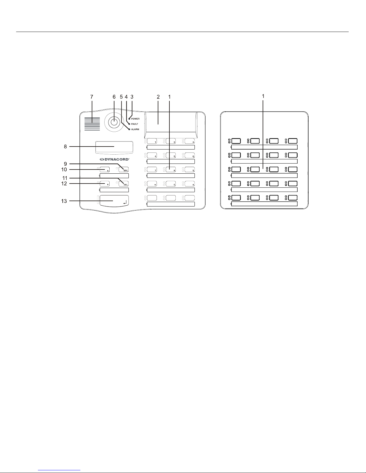
Top view
1 Selection buttons Selecting single zone or group with green/yellow LEDs
2 Optional Key-Slots For up to 3 covered buttons or key-locked switches
3 POWER LED Green if power supply active
4 FAULT LED Yellow if a fault occured
5 ALARM LED Red if alarm is active
6 Microphone Supervised goose-neck microphone
7 Speaker Playback of signal tones
8 Display Shows information on system state or error messages of the
paging console or the PROMATRIX 8000 system
9 STOP (ESC) button Cancels a signal
10
ON (
n) button
Switch on/off the PROMATRIX 8000 system
11 ALL/CLEAR (DEL) button Selects all zones and groups
12
PROGRAM (
p) button
Program assign mode for background music
13 TALK button Activates a message for pre-selected areas or groups
Paging Console
Owner‘s Manual 7
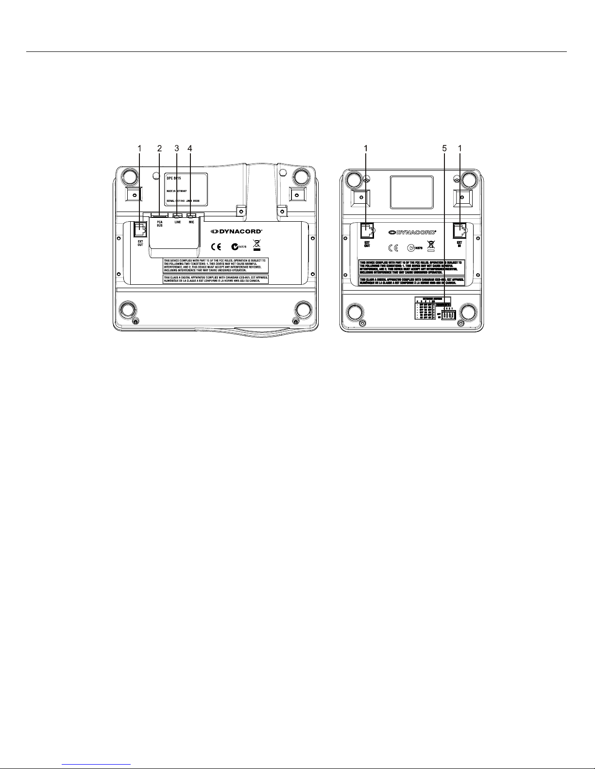
Bottom view
1 EXT interface Interface for DPC 8120 paging console extension
2 PCA BUS port Interface for PROMATRIX 8000 System Controller
3 LINE/PTT interface Interface for external audio source or PTT switch
4 MIC interface Interface for external microphone
5 EXTENSION ADDRESS DIP switch for address selection of paging console extension

Paging Console
8 Owner‘s Manual
2.1 Indications
The following table provides you with an overview of the most important LED-indications.
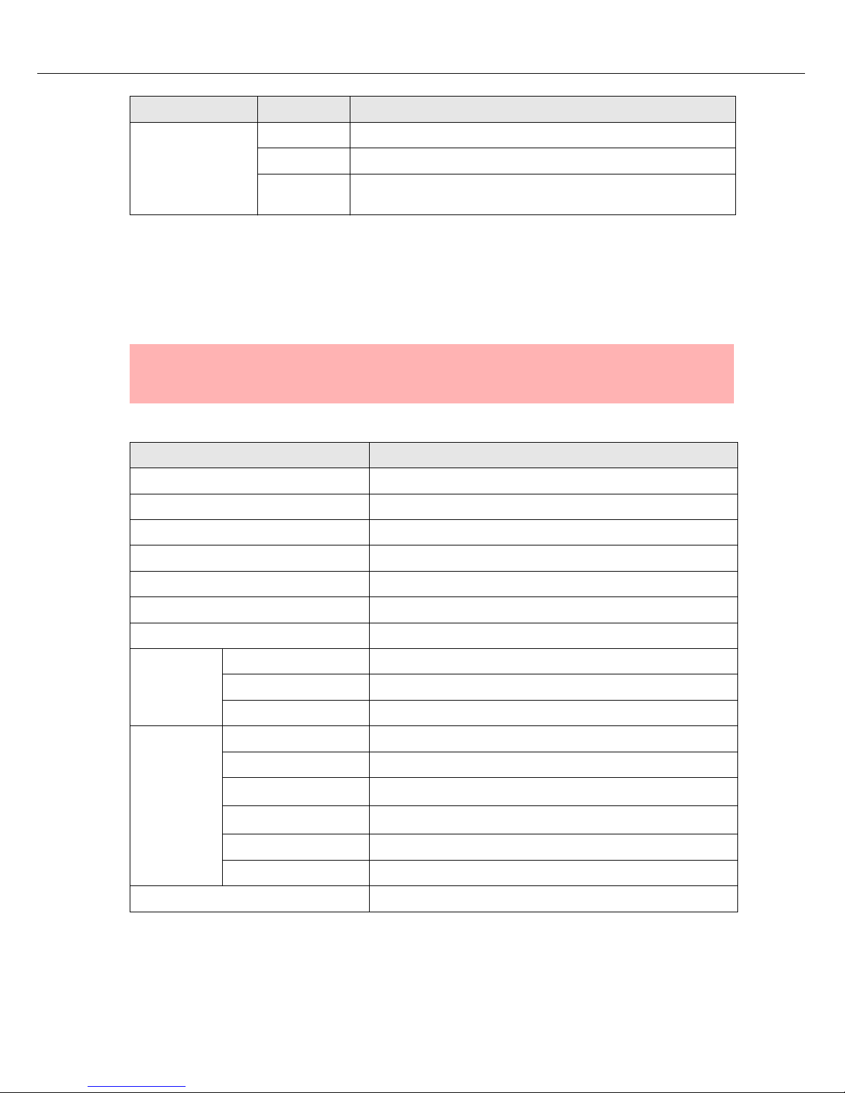
LED Status Description
Selection (green)
off No group or area selected
lights green Area or group selected / special function activated
Selection (yellow)
off Group or area available
flashing Group or area busy (alarm signal)
on
• Operation mode: Group or area busy (alarm signal or background music is not indicated)
• Program assign mode: Background music assigned to group
or area
ON (
n)
off System is OFF (stand-by mode)
lights green System is ON and ready for operation
blinks green System has been turned on and is booting (initialization)
PROGRAM (
p)
off Paging console is in message mode or setup mode
lights green Paging console is in program assign mode
STOP (ESC)
off No signal can be stopped
lights green Pressing the STOP button aborts a signal
ALL/CLEAR (DEL)
off No collective call selected
lights green Collective call pre-selected
TALK (
)
off Selected groups or areas not busy, clear for call
on During own message
slow blinking,
green
Low priority paging station launches a call in selected areas;
interruption on cost of the momentary microphone terminal is
possible
fast blinking,
green
System is busy with a higher priority transmission (message,
gong, alarm), interruption is not possible, already launched call is
interrupted by events with higher priority setting
POWER
off Power supply is deactivated/broken
lights green Power supply is activated
FAULT
off PROMATRIX 8000 system ok
lights yellow A fault exists in the PROMATRIX 8000 system, see LC-display
for details
blinks yellow A new fault occured in the PROMATRIX 8000 system, see LC-
display for details
Paging Console
Owner‘s Manual 9
2.2 Factory Presets
When shipped, the selection keys 1 - n are assigned to the corresponding areas 1 - n offering real
plug‘n‘play; the paging station is ready for operation directly after connection and switching the system
power ON.
The paging stations provide the following factory pre-set functions and characteristics:
ALARM
off No alarm signal launched
lights red Alarm signal has been launched from any source
blinks red Alarm signal has already been stopped, but keeps running until
signal-end
CAUTION:
When connecting several paging consoles to one DPM 8016, setting every single on to
its individual, exclusive address (1...16) is of major importance.
Parameter Setting / Description
CAN address 0 (disconnected)
Priority 5 (priority for messages)
Name DPC 8015
Password Setup menu password protected, Default-Passwort: 2222
Pre-gong signal Off
Buzzer On (acoustic alert signal)
Compressor Off
Optionen
Alarm button Not programmed
Key-lock switch Not programmed
PTT microphone Not programmed
Button
assignment
Selection buttons 1-n Selecting areas 1...n (button 1 = area 1, button 2 = area 2,...)
TALK Call in pre-selected areas, priority 5
ON (
n)
Switching the system ON / OFF, priority 5
PROGRAM (
p)
Assigns a program to pre-selected areas
STOP (ESC) Terminates any locally launched signal (gong, text, alarm)
ALL/CLEAR (DEL) Selecting collective call / deselecting selected areas
Special functions Not programmed
LED Status Description

Paging Console
10 Owner‘s Manual
3 Operation
3.1 LC-display
Depending on the actual operational status of the PROMATRIX 8000 system, the LC-display shows
information on time, operation mode, user notes, setting up, fault messages including precise device /
module specification, etc.
Status messages
During error free operation of the PROMATRIX 8000 system the LC-display shows the name / description
of the paging console in line 1 and the current date and time in line 2.
Error messages
An error within the PROMATRIX 8000 system is indicated at the paging console in following way:
• The FAULT LED is blinking and a warning signal sounds via the integrated loudspeaker.
• The description of the error is indicated in the LC-display. If several errors exist at the same time the
corresponding error messages are indicated alternating.
• By pressing the STOP button the acoustic warning signal stops and the FAULT LED changes from
blinking to permanently on.
• The FAULT LED lights as long as the error in the PROMATRIX 8000 system exists.
3.2 Operation mode
After power on the paging console is in operation mode. For configuring the paging console the setup
mode is used. Several key functions differ between setup mode and operation mode, see following table.
Operation mode Setup mode
n (ON) The n button turns the system‘s power on or off. Turning the
power on can take several seconds. The ON LED blinks while
the system boots. The ON LED lights steadily when the system is operational. To prevent inadvertent erroneous operating pressing the key for at least 3 seconds is necessary when
turning the power off. It is also possible to prohibit the operation of the ON key during the configuration procedure.
In setup mode this
button is used to
select the previous
parameter/menu
item.
ESC (STOP) Pressing the STOP button cancels an output alarm signal or
text message. Only events that were triggered from a specific
paging console can be stopped from the exact terminal with
the exception of the directing station. This terminal allows
canceling all signals.
This button is used
to cancel the editing of a parameter
or to move upwards
in the menu tree.

Paging Console
Owner‘s Manual 11
Selective Call
The user can launch calls or announcements into freely selectable areas or groups.
Pressing a single or several selection buttons defines areas or groups where a call is launched into –
corresponding green LEDs will light. By pressing the key of an already pre-selected line once again
deactivates that line and the corresponding green LED goes out. If the yellow LED of a selection button
lights, the corresponding area or group is busy.
After making a selection, pressing the TALK button ignites the call. Prior hereto, the TALK LED allows
checking whether all lines and the paging station input are actually free. If single lines or the terminal input
are busy with lower priority transmissions, the TALK LED will blink slowly. Whilst making an announcement
is possible, this will interrupt any other transmitted event. If single lines or the terminal input are busy with
p (PROGRAM)
Pressing the PROGRAM button selects the program assign
mode. The selection keys are used in this mode to assign a
program (background music) to the desired areas or groups.
The PROGRAM LED lights while being in the program assign
mode. In this case the green selection LEDs indicate the
areas / groups the program is being transmitted into.
Keeping the ON button pressed and simultaneously pressing
the PROGRAM key selects the setup mode. Now you can
alter preferences or make other changes as described in the
chapter Paging Console Configuration in Setup mode on
page 14. The setup mode is automatically canceled when for
approximately 15 seconds no entry or change has been
made.
In setup mode this
button is used to
select the next
parameter/menu
item.
DEL (ALL/
CLEAR)
The ALL button allows the selection of all programmed areas
at once for transmitting messages, gong or alarm signals,
vocal messages, or to assign programs. On time pressing
selects all areas. The corresponding green selection LEDs
and the ALL LED are lit. Subsequent pressing cancels
(clears) the selection.
Deletes the currently selected
parameter.
TALK This button activates a message for pre-selected areas or
groups. The TALK LED blinks when one or several areas are
busy or when an event with higher priority setting interrupts
the output message (see page 8 for details). The optional
toggle mode of the key is configured via IRIS-Net.
Confirms the
parameter change
or selects the highlighted menu item.
Selection buttons The 15 selection buttons with corresponding green / yellow
LEDs are used to pre-select areas or groups for the reproduction of messages, gong or alarm signals, vocal messages, or
to assign programs (pressed once = ON, subsequently
pressed = OFF). The LEDs indicate the momentary selection
status (also refer to page 8). It is also possible to assign special functions or no function at all (no function assigned) to the
selection buttons. Assigning functions is performed during the
configuration procedure via IRIS-Net.
Enter the corresponding number
of the key.
Operation mode Setup mode

Paging Console
12 Owner‘s Manual
higher priority signals, the TALK LED will vastly blink and the calling attempt is ignored (also refer to the
description of indications).
The TALK LED lights during the transmission of an announcement. The TALK button has to be pressed
during the whole message.
The TALK LED blinks when one or several areas are busy or when an event with higher priority setting
interrupts the output message (see paragraph indications). In the latter, it is necessary to repeat the
message.
Until the user makes any changes, the defined selection stays memorized, even after releasing the TALK
button. Pressing the ALL/CLEAR button two times de-selects the entire selection.
Collective Call
The announcement is launched into all areas of the entire installation.
The procedure is similar to making a selective call. First, all areas of the installation are selected by
pressing the ALL/CLEAR button. Pressing the TALK button activates the collective call. During the
transmission of a call, all area and/or group LEDs as well as the ALL LED will light (also refer to page 8).
The TALK button has to be pressed down until the end of the announcement. BUSY LED indication is
equivalent to the selective call.
General Alarm
A general alarm signal is always transmitted to all lines of the entire installation.
Pressing the covered ALARM button launches the integrated alarm. The button lights during the
transmission of the alarm signal. The alarm has priority over any announcement or other event, except for
those that were ignited from the directing paging station.
Pressing the STOP key cancels the alarm.
NOTE:
The launch of an alarm does not depend on a paging console’s priority setting it had
been activated from. Launching an alarm is possible from any microphone terminal at
any time, even when the system is in stand-by mode. A running alarm is optically and
occasionally also acoustically indicated at every paging station.

Paging Console
Owner‘s Manual 13
Selective Alarm
A selective alarms allows to transmit alarm signals into selected lines.
Similar to the procedure for making a selective call you first have to select areas or groups to which the
alarm signal shall be transmitted. Afterwards, pressing the covered ALARM key starts the selective alarm.
The button lights during the transmission of an alarm. Already now, you are able to enter the lines for the
following alarm.
Pressing the STOP button cancels the alarm.
Canceling Signals
Pressing the STOP button cancels alarms, gong signals and text message transmissions. The functionality
of the STOP button (e.g. priority, local events) is configurable via IRIS-Net. Events can only be terminated
at the paging station they were launched from with the exception of the directing terminal (paging console
with the highest priority). Through the directing station it is possible to cancel any signal in progress.
System ON / OFF
The ON button switches a PROMATRIX 8000 system ON or OFF. Mostly, it is not intended that any paging
station be provided with the possibility to do so. Thus, this function can be programmed via IRIS-Net.
When the system is in stand-by mode, the ON LED is off. Pressing the ON button turns the PROMATRIX
8000 system’s power on which can take several seconds, while the ON LED is blinking. Once the system
is ready for operation, the ON LED lights continuously (which also applies for all paging stations of the
entire installation).
To switch the system OFF, you have to press the ON button for approximately 3 second. This is to prevent
inadvertently turning off the system.
Pressing an ALARM button or igniting an alarm sequence at external terminals automatically switches the
PROMATRIX 8000 system’s power on and boots the system.
Program Assignment
Activating this feature during the PC-configuration procedure allows the assignment of programs to
individual areas and groups of the entire installation during the PC-configuration procedure.
1. Set the paging station to program assign mode by pressing the PROGRAM button.
2. Select the program by pressing the n
or p key.
NOTE:
The launch of an alarm does not depend on a paging console’s priority setting it had
been activated from. Launching an alarm is possible from any microphone terminal at
any time, even when the system is in stand-by mode. A running alarm is optically and
occasionally also acoustically indicated at every paging station.

Paging Console
14 Owner‘s Manual
The second line of the LC-display indicates the description of the programs, as they were definied
during configuration via IRIS-Net.
3. Pressing a single or several selection buttons assigns the outputted program (background music) to
the selected areas and groups. If the yellow LED of a selection key lights, the program can not be
assigned to this area or group.
4. In order to leave the program-assign mode press the ESC button several times till the operation mode
of the paging console is reached.
It is also automatically canceled after approximately 15 seconds.
Special Functions
Generally, assigning a function to each selection key is possible. This allows utilizing a paging station to
control the lighting, door openers, blinds, etc.; even controlling volume settings is possible through the use
of the n
or p buttons. When shipped, there are no special functions assigned.
3.3 Paging Console Configuration in Setup mode
Configuring paging consoles is preferably performed on the central unit via computer and using the IRISNet software. This represents the most convenient way without any limitation, while a paging terminal itself
offers only limited programming ability. For configuring the paging console via its LC-display the paging
console has to be switched to setup mode as described in following section.
Using the setup mode
In setup mode the configuration of the paging console itself and parts of the PROMATRIX 8000 system
can be editied via the LC-display. Please note that several button functions differ between setup mode and
operation mode. Alternate functions are marked on the right bottom corner of the individual key area.
1. Pressing first the PROGRAM button and then the ON key simultaneously engages a paging station‘s
setup mode.
The first menu item is indicated in the LC-display.
2. Use the paging console buttons for menu navigation and editing parameters.
See following pages for a detailed description of the paging console menu.
3. Pressing the ESC button several times returns to operation mode.
Paging Console
Owner‘s Manual 15
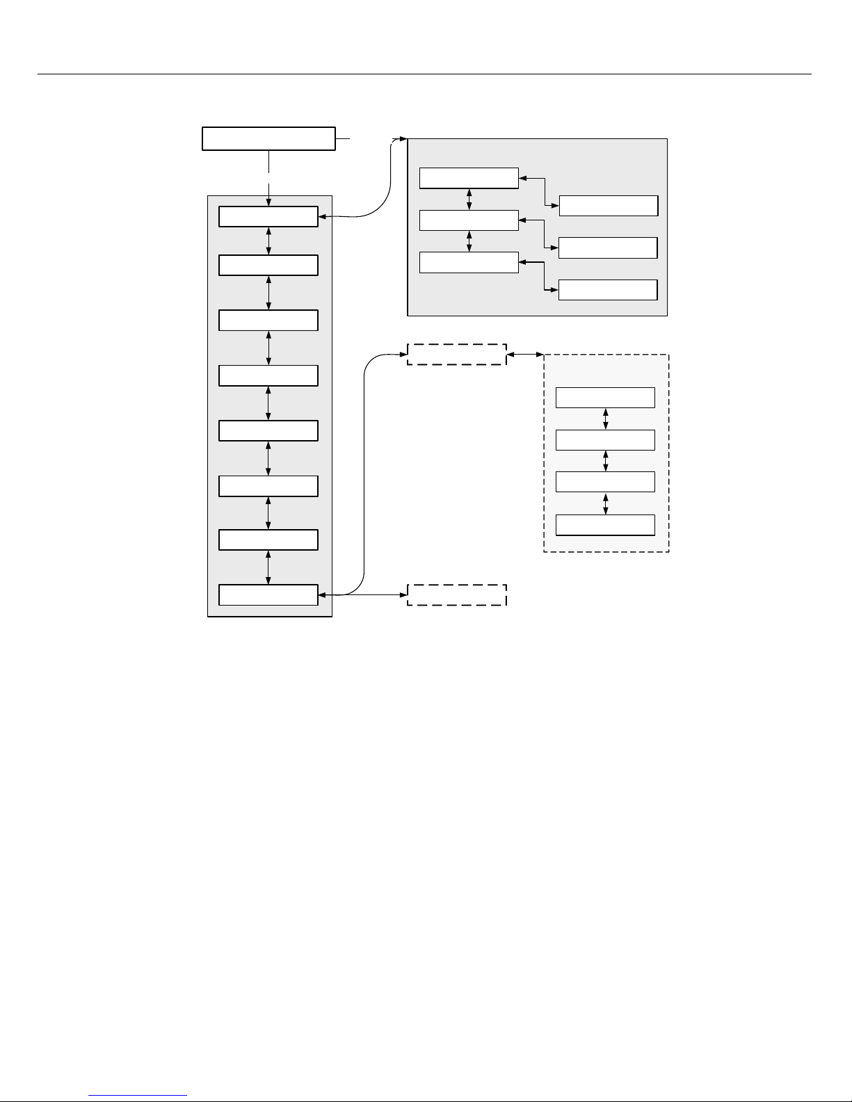
Menu structure
3.4 User menu
Program assignment
This menu item allows the assignment of programs to individual areas and groups of the entire installation.
The program-assign mode can also be reached directly from operation mode by pressing the PROGRAM
button. Program transmission has always the lowest priority.
In single-program configuration the music reproduction into all areas of the installation is attenuated for the
time of an announcement. In double-program configuration parallel transmission of a background music
program into rooms that are not part of an actual announcement selection is possible as well. If every line
incorporates its own LF-output and separate power amplifiers, mixing announcements and background
programs is possible in any way.
Pressing the
button opens the Programme sub menu. The sub menu is described in the following
sections.
Program assignment
LCD brightness
Buzzer
Pre-Gong
Operation mode
PROGRAM + ON
Date / Time
Password
Setup Menu
Service Menu
LED test
Program 1
:
Program 4
PROGRAM 1 - 4
Volume 1
Firmware version
CAN address
CAN baudrate
CAN termination
SETUP
PROGRAM
LCD contrast
Volume 4
:

Paging Console
16 Owner‘s Manual
Program X
The list of available programs is shown. Select a program by pressing the nor p buttons. If there are
already areas or groups assigned to the currently selected program, the corresponding green selection
LEDs are lit.
Pressing a single or several selection keys assigns the outputted program (background music) to the
selected areas and groups.
The program assignment stays memorized until the selection keys are pressed again. If the yellow led of a
a selection button is lit, the program can not be assigned to this area or group
Press the
button to open the Volume X menu, see following section.
Volume X
This menu item indicates the currently set volume of the program. The volume can be adjusted with a step
size of 1 dB by using the n
or p buttons. Press and hold the nor p button for fast increment or decrement
of volume.
Pressing the
button stores the set volume level and the display returns to the Program X menu.
Pre-Gong
It is possible to program a pre-gong signal that is heard before an announcement. The pre-gong signal is
transmitted into the selected areas when pressing the
button. You can begin with your announcement
during the transmission of the pre-gong signal; you can talk "into" the pre-gong.
Pressing the
button opens the Pre-Gong dialog box where the current state of the Gong („on” or „off”) is
indicated. Press the n
or p button to activate/deactivate the pre-gong. Pressing the button stores the
setting and returns to the user menu.
Buzzer
The integrated buzzer can be programmed as acoustic alert signal. During failure, malfunction, or as
general alert a buzzing sound is heard. When an alarm has been launched, the buzzing can be heard for
the whole period of the alarm.
Pressing the
button opens the Buzzer dialog box where the current state of the buzzer („on” or „off”) is
indicated. Press the n
or p button to activate/deactivate the pre-gong. Pressing the stores the setting
and returns to the user menu.
NOTE:
The program assignment becomes effective immediately.
NOTE:
The volume adjustment becomes effective immediately.

Paging Console
Owner‘s Manual 17
Date / Time
The connected paging stations allow setting the date and time of the PROMATRIX 8000 system.
Pressing the
button opens the Date / Time dialog box, which allows selecting day, month, year, hour,
minute or seconds by pressing the n
or p buttons. Edit the parameters be pressing the 0-9 buttons.
Pressing the
button stores the setting and returns to the user menu.
LCD contrast
Paging consoles with display allow the user to individually adjust LCD contrast and viewing angle. This
allows optimum legibility from the user's location.
Pressing the
button opens the LCD contrast dialog box where the user can select a contrast setting in
the range of 0 % to 100 % by using the n
or p buttons.
Pressing the
button stores the setting and returns to the user menu.
LCD brightness
Pressing the button opens the LCD brightness dialog box where the user can set the display brightness
by using the n
or p buttons.
Pressing the
button stores the setting and returns to the user menu.
LED test
This menu item allows a test of all paging console LEDs including paging console extension, if available.
Press the
button for activating the LED test, all LEDs are blinking. Pressing the button again
deactivates the LED test and returns to the user menu.
Password
Pressing the button opens the Password dialog box where the user can enter a password using the 0-9
buttons. Press the
button to commit the password.
 Loading...