

Page 1
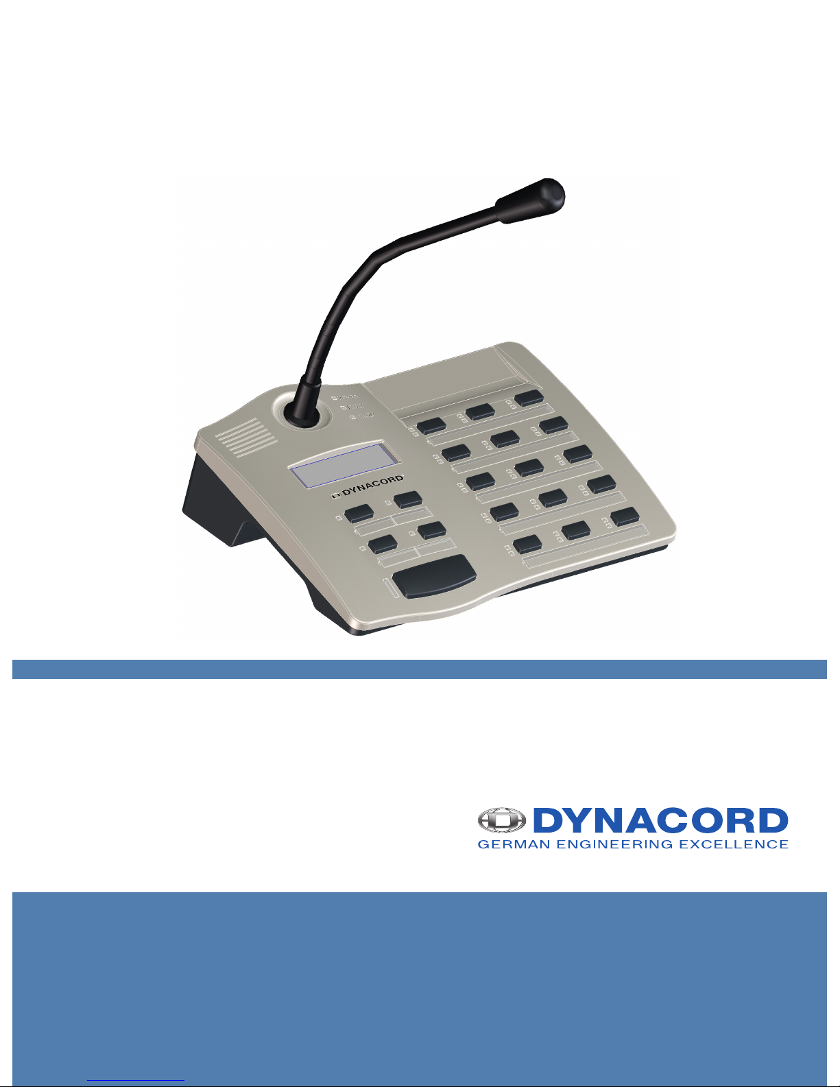
DPC 8000
en |
Page 2

Page 3

Table of contents
1
Safety notes 4
2
Brief description 6
3
System overview 7
4
Scope of delivery and warranty 8
5
Installation 9
5.1 Top 9
5.2 Bottom 11
5.3 Delivery condition 12
5.4 Button labeling 13
5.5 Retrofit options 13
5.5.1 Alarm button (EB DPC) 13
5.5.2 Key switch (NRS 90231) 14
6
Activation 16
6.1 PCA BUS interface 16
6.1.1 Interface description 16
6.2 LINE interface 17
6.3 MIC interface 17
6.4 EXT interface 18
7
Configuration 19
7.1 User menu 21
7.2 Setup menu 22
8
Operation 24
8.1 Indicators 24
8.2 Functions 25
9
Maintenance 29
10
Technical data 30
10.1 Block diagram 31
10.2 Dimensions 32
10.3 Standards 32
11
Appendix 34
11.1 CAN bus basics 34
11.2 Call station extension 34
DPC 8000 Table of contents | en 3
28-Feb-2013 | |
Page 4
Safety notes
Danger!
The lightning symbol inside a triangle notifies the user of high-voltage, uninsulated lines and
contacts inside the devices that could result in fatal electrocution if touched.
!
Warning!
An exclamation mark inside a triangle refers the user to important operating and service in-
structions in the documentation for the equipment.
1. Read these safety notes.
2. Keep these safety notes in a safe place.
3. Heed all warnings.
4. Observe all instructions.
5. Do not operate the device in close proximity to water.
6. Use only a dry cloth to clean the unit.
7. Do not cover any ventilation slots. Always refer to the manufacturer's instructions when
installing the device.
8. Do not install the device close to heaters, ovens, or other heat sources.
9. Note: The device must only be operated via the mains power supply with a safety ground
connector. Do not disable the safety ground connection function of the supplied power
cable. If the plug of the supplied cable does not fit your mains socket, please contact
your electrician.
10. Ensure that it is not possible to stand on the mains cable. Take precautions to ensure the
mains cable cannot become crushed, particularly near the device connector and mains
plug.
11. Only use accessories/extensions for the device that have been approved by the
manufacturer.
12. Unplug the device if there is risk of lightning strike or in the event of long periods of
inactivity. However, this does not apply if the device is to be used as part of an
evacuation system!
13. Have all service work and repairs performed by a trained customer service technician.
Service work must be carried out immediately following any damage such as damage to
the mains cable or plug, if fluid or any object enters the device, if the device has been
used in rain or become wet, or if the device has been dropped or no longer works
correctly.
1
4 en | Safety notes DPC 8000
28-Feb-2013 | |
Page 5
14. Please ensure that no dripping water or spray can penetrate the inside of the device. Do
not place any objects filled with fluids, such as vases or drinking vessels, on top of the
device.
15. To ensure the device is completely free of voltage, unplug the device from the power
supply.
16. When installing the device, ensure that the plug is freely accessible.
17. Do not place any sources of open flame, such as lit candles, on top of the device.
18. This PROTECTION CLASS I device must be connected to a MAINS socket with a safety
ground connection.
Caution!
Use only manufacturer-approved carts, stands, brackets, or tables that you acquired together
with the device. When using carts to move the device, make sure the transported equipment
and the cart itself cannot tip over or cause injury or material damage.
IMPORTANT SERVICE INFORMATION
!
Caution!
This service information is for use by qualified service personnel only. To avoid the risk of
electric shock, do not perform any maintenance work that is not described in the operating
instructions unless you are qualified to do so. Have all service work and repairs performed by
a trained customer service technician.
1. Repair work on the device must comply with the safety standards specified in EN 60065
(VDE 0860).
2. A mains isolating transformer must be used during any work for which the opened device
is connected to and operated with mains voltage.
3. The device must be free of any voltage before performing any alterations with upgrade
sets, switching the mains voltage, or performing any other modifications.
4. The minimum distance between voltage-carrying parts and metal parts that can be
touched (such as the metal housing) or between mains poles is 3 mm, and must be
observed at all times.
5. The minimum distance between voltage-carrying parts and circuit parts that are not
connected to the mains (secondary) is 6 mm, and must be observed at all times.
6. Special components that are marked with the safety symbol in the circuit diagram (note)
must only be replaced with original parts.
7. Unauthorized changes to the circuitry are prohibited.
8. The protective measures issued by the relevant trade organizations and applicable at the
place of repair must be observed. This includes the properties and configuration of the
workplace.
9. Observe the guidelines with respect to handling MOS components.
Danger!
SAFETY COMPONENT (MUST BE REPLACED BY ORIGINAL PART)
DPC 8000 Safety notes | en 5
28-Feb-2013 | |
Page 6

Brief description
The DPC 8015 is a call station for the PROMATRIX 8000 system. As standard, the call station
has a goose neck microphone with pop shield and permanent monitoring, a total of 20
buttons, an illuminated LC display, and an integrated loudspeaker. The call station can be
modified to suit the user’s requirements by connecting up to five DPC 8120 call station
extensions, each with 20 customizable function and speed dial buttons.
2
6 en | Brief description DPC 8000
28-Feb-2013 | |
Page 7

System overview
The PROMATRIX 8000 system includes the DPC 8015 call station and the DPC 8120 call
station extension. The call station is equipped with a goose neck microphone, and has 15
customizable selection and function buttons and five pre-programmed menu/function buttons.
Up to three alarm buttons or key switches can also be retrofitted. The call station is equipped
with an illuminated LC display (122 x 32 pixels). The call station has the following features:
• Microphone with preamplifier and compressor/limiter switch
• Function and selection buttons with programmable button assignment
• Simple labeling of buttons with labeling strips and format template (file in .doc format
included in the IRIS-Net scope of delivery)
• Possible to install covered alarm buttons or key switches (optional, three installation
slots)
• Possible to connect an external microphone or audio source
• Built-in loudspeaker
• High-resolution LC display
• Comprehensive parameter settings menu on the actual call station
• Microphone and line monitoring
• Error message via LED and buzzer, and error text in the LC display
• Processor control of all functions
• Monitoring of the processor system via watchdog circuit
• Non-volatile FLASH memory for configuration data
The call station is processor-controlled, and equipped with extensive monitoring functions. A
watchdog circuit is built in to monitor the processor system. The internal microphone can be
monitored for function, interruptions, and short-circuits. Line monitoring for the CAN bus and
for audio transmission allows line interruptions and short-circuits to be detected and
indicated to the user. The call stations for the PROMATRIX 8000 system can be configured
quickly and easily using IRIS-Net. A graphical and conversational user interface allows the user
to define all button functions, priorities, options, and other properties.
3
DPC 8000 System overview | en 7
28-Feb-2013 | |
Page 8

Scope of delivery and warranty
Number Component
1 DPC 8015 Call Station
1 Patch cable (3 meters)
1 Operating instructions (this document)
1 Warranty card with safety notes
Table 4.1: DPC 8015 scope of delivery
Number
Component
1 DPC 8120 Call Station Extension
1 6-pin connecting cable for call station extension
1 Connecting holder for call station extension
1 Connecting plate for call station extension
6 Screws (self-tapping)
1 Technical information
1 Warranty card with safety notes
Table 4.2: DPC 8120 scope of delivery
Warranty
For information regarding the warranty, see www.dynacord.com
4
8 en | Scope of delivery and warranty DPC 8000
28-Feb-2013 | |
Page 9
Installation
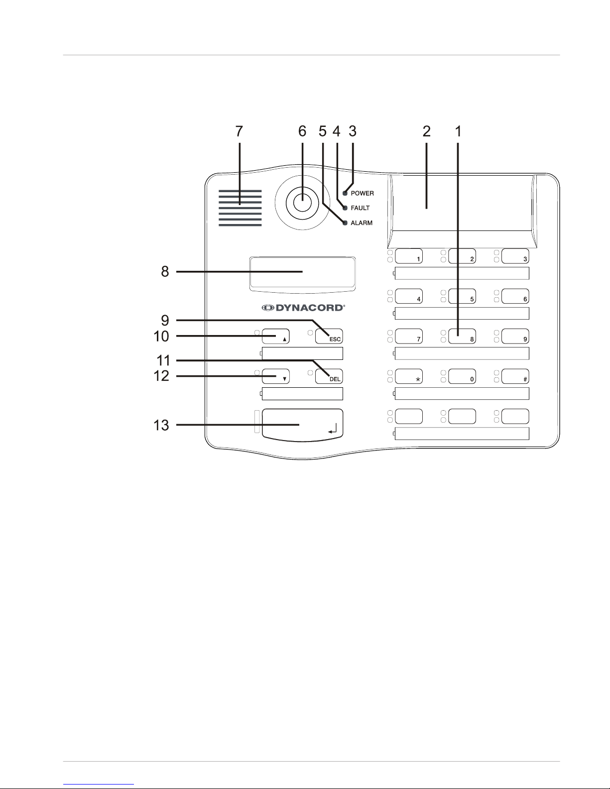
Top
Figure 5.1: DPC 8015
5
5.1
DPC 8000 Installation | en 9
28-Feb-2013 | |
Page 10
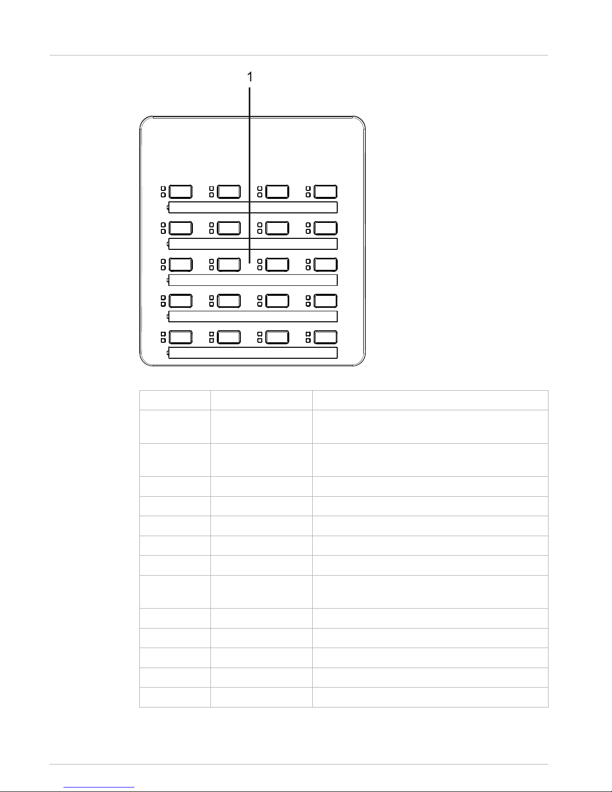
Figure 5.2: DPC 8120
Number
Element Description
1 Selection buttons Circuit and group selection buttons with green and
yellow LED.
2 Button installation
slots
For up to three optional alarm buttons or key
switches
3 POWER LED Illuminates green if the power supply is on
4 FAULT LED Illuminates yellow if an error occurs
5 ALARM LED Illuminates red if an alarm is triggered
6 Microphone Monitored goose neck microphone
7 Loudspeaker Plays back signal sounds
8 Display Status/error displays for the call station or the entire
PROMATRIX 8000 system
9 ESC button Acknowledges and advances to next error message
10 ↑ button Activates the PROMATRIX 8000 system
11 DEL button Selects all zones and groups
12 ↓ button Stops a live audio signal
13 ↵ button For announcements to selected zones
10 en | Installation DPC 8000
28-Feb-2013 | |
Page 11
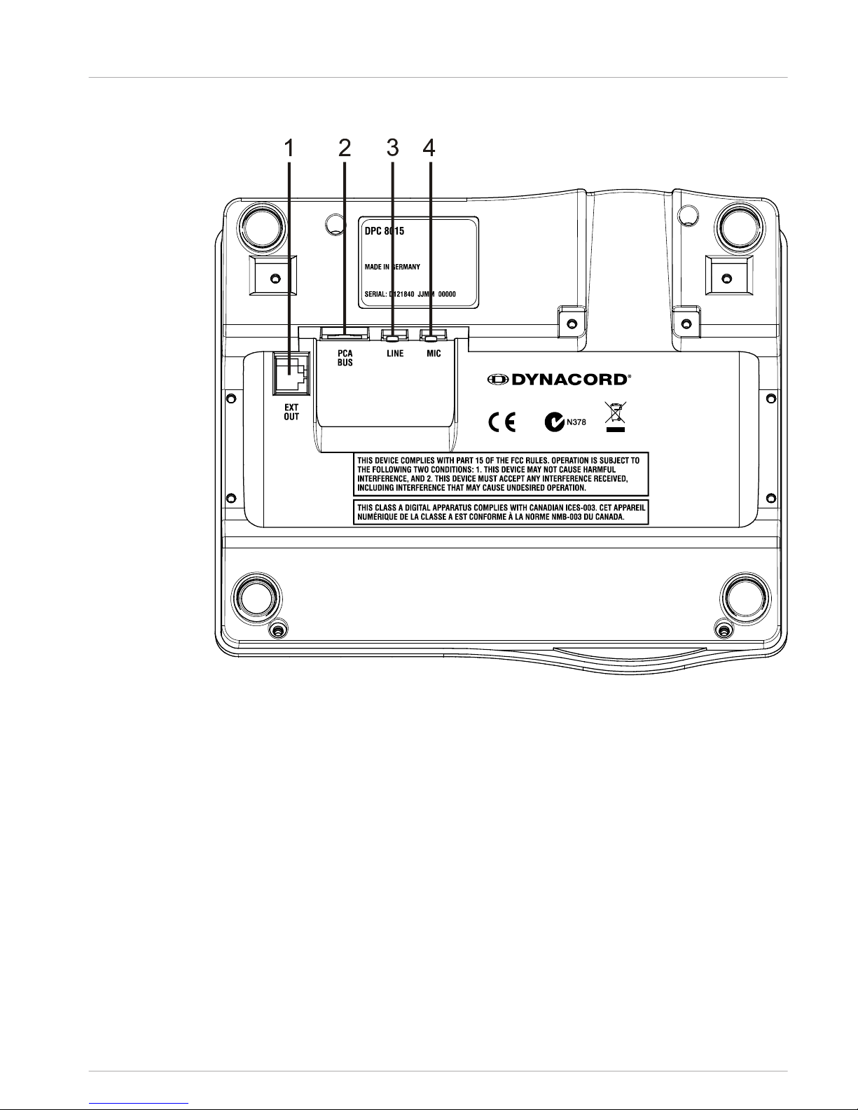
Bottom
Figure 5.3: DPC 8015
5.2
DPC 8000 Installation | en 11
28-Feb-2013 | |
Page 12
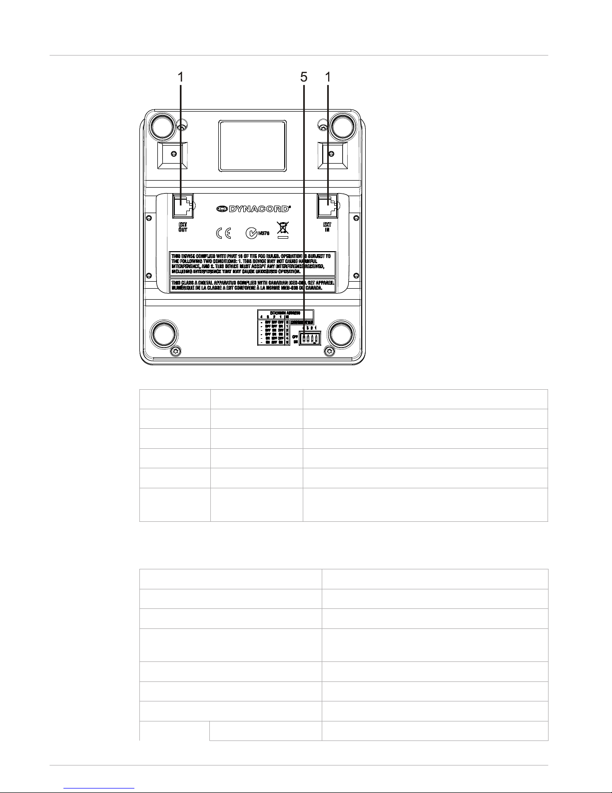
Figure 5.4: DPC 8120
Number
Element Description
1 EXT interface Connection for DPC 8120 call station extension
2 PCA BUS interface Connection to PROMATRIX 8000 CONTROLLER
3 LINE/PTT interface Connection for external audio devices or a PTT button
4 MIC interface Connection for external microphone
5 EXTENSION
ADDRESS
DIP switch for setting the address of the call station
extension
Delivery condition
The call stations are programmed with the following factory functions and properties settings:
Parameters Setting/description
CAN address 0 (disconnected)
Name DPC 8015
Password Setup menu password-protected, default
password: 2222
Opening gong Off
Buzzer On (acoustic warning signal)
Compressor Off
Options Alarm buttons Not configured
5.3
12 en | Installation DPC 8000
28-Feb-2013 | |
Page 13

Parameters Setting/description
Key switch Not configured
External microphone Not configured
Button
assignment
Selection buttons 1–n Selection of circuits 1 through n (button 1 = circuit
1, button 2 = circuit 2 etc.)
↵ Call in selected circuits, priority 5
↑ Switches system on/off, priority 5
↓ Stops a live audio signal.
ESC Acknowledges and advances to next error message
DEL Selects all-call/deletes call pattern
Special functions Not configured
!
Warning!
If several call stations need to be operated via a DPM 8016, each call station must be as-
signed a unique CAN address (1–16). Subsequently changing the CAN address causes the
configuration to change.
Button labeling
The call station buttons are labeled using labeling strips, which are inserted from above. To
label a row of buttons, loosen the respective cover on the left-hand side using a suitable
slotted screwdriver. Insert the labeled strip into the open label field, and close the label field
by evenly pressing down on the cover.
Retrofit options
The DPC 8015 call station can be retrofitted with a maximum of three covered buttons (EB
DPC, item F01U101089) or key switches (NRS90231, item F01U101000). Additional control
elements can be used, for example for triggering alarms in certain areas (selection alarm) or
for switching the system ON/OFF. The functions are assigned via IRIS-Net during
configuration.
Alarm button (EB DPC)
The EB DPC is an optional button for installation in the DPC 8000 series call stations. The
transparent cover cap prevents unintentional actuation of the button. A high-efficiency LED is
integrated for optical visualization, while also ensuring maximum operational reliability. The
button feed lines are monitored by the call station. If an error occurs, this is indicated in the
error log of the PROMATRIX 8000 system.
Figure 5.5: EB DPC
5.4
5.5
5.5.1
DPC 8000 Installation | en 13
28-Feb-2013 | |
Page 14

Assembly
Note the following information regarding installation of the EB DPC in the DPC 8015 call
station.
1. Disconnect the call station from all connectors
2. Unscrew the call station baseplate (4 screws)
3. Unplug the connecting cable from the CN1 plug connector
4. Prepare installation location: Use a sharp object (knife, scriber, or similar) to carefully
punch through and cut out the pre-cut rectangle on the inside of the housing. Perform
any follow-up work that may be required to the installation location (e.g. filing, trimming)
5. Mount the button into the installation location, and press in evenly (it must be possible
for the cover cap to open upward)
6. Depending on whether the right/middle/left installation location is used, plug the ribbon
cable into plug connector CN201/CN202/CN203 on the circuit board
7. Plug the connecting cable into CN1 again
8. Re-attach the call station baseplate
9. Re-connect the connections
10. Configure the button using the software
Key switch (NRS 90231)
The NRS 90231 is an optional key switch for installation in the DPC 8000 series call stations.
The key switch feed lines are monitored by the control station. If an error occurs, this is
indicated in the error log of the PROMATRIX 8000 system.
5.5.2
14 en | Installation DPC 8000
28-Feb-2013 | |
Page 15

Figure 5.6: NRS 90231
Assembly
Note the following information regarding installation of the NRS 90231 in the DPC 8015 call
station.
1. Disconnect the call station from all connectors
2. Unscrew the call station baseplate (4 screws)
3. Unplug the connecting cable from the CN1 plug connector
4. Prepare installation location: Use a sharp object (knife, scriber, or similar) to carefully
punch through and cut out the pre-cut circle on the inside of the housing Perform any
follow-up work that may be required to the installation location (e.g. filing, trimming)
i
Notice!
Note that the lines can only be soldered once the switch has been installed.
5. Bore through the pre-cut side opening for the holding pin of the key switch cover
6. Align the switch and screw tightly in place using the supplied knurled screw
7. The supplied 4-pin cable and the resistances must be connected as shown in the
following diagram
R
2
1
0
k
1 rt
2 gr
3 gr
4 gr
CN1-4
CN1-3
CN1-2
CN1-1
3
4
R1
10k
Figure 5.7: Connecting NRS 90231
8. Note the connection sequence of the ribbon cable. The two external cables 1 (red) and 4
(green) must be cut as close to the cut-off point as possible and isolated. The two
internal cables 2 (green) and 3 (green) must be soldered to switch connections 3 and 4.
The polarity is not important
9. Depending on whether the right/middle/left installation location is used, plug the ribbon
cable into plug connector CN201/CN202/CN203 on the circuit board
10. Plug the connecting cable into CN1 again
11. Re-attach the call station baseplate
12. Re-connect the connections
13. Configure the button using the software
DPC 8000 Installation | en 15
28-Feb-2013 | |
Page 16

Activation
PCA BUS interface
i
Notice!
If the call station is connected to a DPM 8016 via the PCA BUS, the call station is automatical-
ly configured depending on the set CAN address. The call station is ready to use after a few
seconds.
The cable for connecting the PCA BUS interface must be fed under the suspension bracket
(see the following diagram).
Figure 6.1: PCA BUS interface
Interface description
The PROMATRIX CAN Audio (PCA) BUS interface is used to connect the DPC 8015 call station
with a PROMATRIX 8000 system. This is an 8-pin RJ-45 connector that assigns the power
supply, control interface (CAN bus), and audio interface. The call station must be connected
to the respective wall-mount socket via the enclosed network cable (3 m). The following image
shows the assignment of the PCA BUS socket and the corresponding RJ-45 connector.
i
Notice!
For CAN, AUDIO IN and AUDIO OUT, the wires must be twisted as pairs in each case.
8: AUDIO OUT -
2: CAN_GND
4: CAN_H (+)
5: CAN_L (-)
1 8
7: AUDIO OUT +
1: +24V DC
3: AUDIO IN +
6: AUDIO IN -
Figure 6.2: Assignment of the PCA bus interface
6
6.1
6.1.1
16 en | Activation DPC 8000
28-Feb-2013 | |
Page 17

Figure 6.3: Assignment of the PCA bus connector
LINE interface
Usage as audio input
The LINE interface allows an external audio device (e.g. CD player) to be connected. If
configured in IRIS-Net, the audio source connected to this interface can be used for a program
in the PROMATRIX 8000 system. The following diagram shows the assignment of a stereo jack
plug (3.5 mm, "mini jack") for connection to the LINE socket.
LINE_LEFT
LINE_RIGHT
LINE_GND
Figure 6.4: Assigning the LINE plug as audio input
i
Notice!
During announcements, the audio signal on the LINE interface is interrupted.
Use as PTT contact input
When connecting a PTT microphone to a DPC 8015, the LINE interface is used as input for the
PTT contact. The PTT function must be set for the call station in IRIS-Net during configuration.
The following diagram shows the corresponding assignment of a stereo jack plug (3.5 mm,
"mini jack").
PTT
Figure 6.5: Assigning the LINE plug as PTT contact input
MIC interface
The MIC interface allows a second microphone to be connected. A conventional "PC
microphone" (VCC = 3.3 V) can be connected. The following diagram shows the assignment of a
3.5 mm stereo jack plug for connection to the MIC jack.
MIC
MIC_VCC
MIC_GND
Figure 6.6: Assignment of the MIC plug
6.2
6.3
DPC 8000 Activation | en 17
28-Feb-2013 | |
Page 18

EXT interface
This socket is primarily used to connect a DPC 8120 call station extension. To do so, connect
the DPC 8120 to the EXT socket of the call station via the connecting cable provided.
6.4
18 en | Activation DPC 8000
28-Feb-2013 | |
Page 19

Configuration
The call stations of a PROMATRIX 8000 system should be configured on the control panel via a
PC using IRIS-Net as this is the simplest method, and there are no restrictions. Only limited
programming is possible on the actual call stations themselves. To configure the call station
via the LC display, the call station must be switched to menu mode as described below.
Use in menu mode
In menu mode, the call station and certain elements of the PROMATRIX 8000 system can be
configured via the built-in LC display. In this mode, certain buttons have a different function
than they would in announcement mode. The alternative assignment is specified on the lower
right of the respective button.
1. Press the ↓ button, keep it held down, and press the ↑ button at the same time. The
display switches from announcement mode to menu mode
2. Use the call station buttons to navigate through the menu and enter settings. The
following pages contain information about the menu structure
3. To exit the menu, keep pressing the ESC button until the status display of the
announcement mode appears in the LC display.
7
DPC 8000 Configuration | en 19
28-Feb-2013 | |
Page 20

Program assignment
LCD brightness
Buzzer
Pre-Gong
Operation mode
Date / Time
Password
LED test
Program 1
:
Program 4
PROGRAM 1 - 4
Volume 1
Firmware version
CAN address
CAN baudrate
CAN termination
SETUP
LCD contrast
Volume 4
:
Setup Menu
+¯
Monitor Vol.
Figure 7.1: Menu structure
20 en | Configuration DPC 8000
28-Feb-2013 | |
Page 21

User menu
Program selection
The call station allows programs to be assigned to individual circuits or groups of the
PROMATRIX 8000 system. Program transfer has the lowest priority. With single-program
technology, the music must be muted or switched off in all circuits for the duration of an
announcement. With dual-program technology, music can still be played in rooms where no
announcement is being made. If a separate NF output and amplifier is available for each line,
announcements and background music can be transmitted completely independently of each
other. Pressing the ↵ button takes the user to the Programs submenu. The entries contained
in this submenu are described below.
Program X
A list of the programs assigned to the call station in IRIS-Net is displayed. Pressing the ↑ or ↓
button toggles between the programs. If zones have already been assigned to the program,
the green LEDs on the selection buttons show the selected circuits/groups.
By pressing the selection buttons, the required circuits/groups can be selected. This is
indicated by the corresponding green LEDs.
i
Notice!
The zone assignment is immediately accepted in the PROMATRIX 8000 system.
The assignment remains valid until the selection buttons are pressed repeatedly. If the yellow
LED of a selection button illuminates, the program cannot be assigned to this circuit or group
for topological reasons.
Pressing the ↵ button takes the user to the Volume X submenu, which is described below.
Volume X
The volume currently set in the program is displayed. Pressing the ↑ or ↓ button sets the
volume of the program. The volume level is increased or decreased in 1 dB steps. Pressing and
holding the ↑ or ↓ buttons continuously increases or decreases the volume.
i
Notice!
The new volume level is immediately accepted in the PROMATRIX 8000 system.
Pressing the ↵ button accepts the setting selected, and returns the user to the Program X
menu.
Opening gong
An opening gong can be programmed for announcements. In announcement mode, the
opening gong is transmitted to the selected circuits each time the ↵ button is pressed. The
announcement can begin during the opening gong, meaning that the announcer can "interrupt"
the gong. Pressing the ↵ button takes the user to the Opening Gong submenu. The current
setting of the opening gong ("on" or "off") is displayed. Pressing the ↑ or ↓ buttons toggles
between these two statuses. Pressing the ↵ button accepts the setting selected, and returns
the user to the User menu.
7.1
DPC 8000 Configuration | en 21
28-Feb-2013 | |
Page 22

Buzzer
The built-in loudspeaker can be programmed as an acoustic warning signal. The signal tone
sounds in the event of incorrect operation or malfunction, or as a warning. Pressing the ↵
button takes the user to the Buzzer submenu. The current setting of the buzzer ("on" or "off")
is displayed. Pressing the ↑ or ↓ buttons toggles between these two statuses. Pressing the ↵
button accepts the setting selected, and returns the user to the User menu.
i
Notice!
This menu option requires a password.
Date/time
The date and time can be set for the PROMATRIX 8000 system on the call stations. Pressing
the ↵ button takes the user to the Date/Time submenu. Pressing the ↑ or ↓ button toggles
between the day, month, year, hours, minutes, and seconds. Use the 0–9 buttons on the call
station to input entries. Pressing the ↵ button accepts the setting selected, and returns the
user to the User menu.
LCD contrast
Pressing the ↵ button takes the user to the LCD Contrast dialog box. In this dialog box, the
LCD contrast can be adjusted to the viewing angle by pressing the ↑ or ↓ button. This helps
achieve maximum readability for the respective position. Pressing the ↵ button accepts the
contrast setting selected, and returns the user to the User menu.
LCD brightness
Pressing the ↵ button takes the user to the LCD Brightness dialog box. In this dialog box, the
display brightness can be adjusted by pressing the ↑ or ↓ button. Pressing the ↵ button
accepts the brightness selected, and returns the user to the User menu.
LED test
Pressing the ↵ button activates the LED test for the call station and all connected call station
extensions. All LEDs flash during this test. Pressing the ↵ button deactivates the LED test, and
returns the user to the User menu.
Password input
i
Notice!
The default password for activation of the Setup Menu and Buzzer menu items is 2222
Pressing the ↵ button takes the user to the Password dialog box. Use the 0–9 buttons on the
call station to input entries. Passwords are used to activate call station options.
Setup menu
Pressing the ↵ button takes the user to the Setup menu. The entries in this submenu are
described in section Setup menu, page 22 . If the Setup Menu menu option is not visible, it
must be activated via the Password menu item.
Setup menu
The Setup menu is accessed via the Setup Menu entry in the User menu. If this menu option is
not visible, it must be activated via the Password menu option.
7.2
22 en | Configuration DPC 8000
28-Feb-2013 | |
Page 23

CAN address
Pressing the ↵ button takes the user to the CAN Address dialog box. Pressing the ↑ or ↓
button sets the required CAN address. The call station can be assigned a CAN address
between 1 and 16.
Pressing the ↵ button accepts the address selected, and returns the user to the Setup menu.
!
Warning!
By default, all call stations have the address OFF (no address). First of all, a valid address
must be entered. Only one call station address may be used for each DPM 8016!
CAN baud rate
Pressing the ↵ button takes the user to the CAN Baud Rate dialog box. Pressing the ↑ or ↓
button toggles between the available baud rates. Pressing the ↵ button accepts the setting
selected, and returns the user to the Setup menu.
CAN termination
Pressing the ↵ button takes the user to the CAN Termination dialog box. Pressing the ↑ or ↓
button activates or deactivates the termination on this call station. Termination must be
activated on the call station that is connected to the end of the CAN bus. Please see section
CAN bus basics, page 34.
Pressing the ↵ button accepts the setting selected, and returns the user to the Setup menu.
Firmware version
Displays the version of the call station firmware.
Monitor vol.
Pressing the ↵ button takes the user to the Monitor Vol dialog box. Pressing the ↑ or ↓ button
adjusts the volume level of the loudspeaker.
Pressing the ↵ button accepts the setting selected, and returns the user to the Setup menu.
DPC 8000 Configuration | en 23
28-Feb-2013 | |
Page 24

Operation
Indicators
The meanings of the call station LED indicators are summarized below. Standard configuration
of the call station is assumed.
LED Status Description
Zone (green) Off Circuit or group not selected
Illuminated green • Circuit or group selected
• Special function activated
• Direct call activated
Zone (yellow) Off Circuit or group not assigned
Flashing yellow Circuit or group assigned (alarm or
evacuation)
Illuminated yellow • Announcement mode: Circuit or group
assigned (everything except alarm,
evacuation, or background music)
• Program assignment mode: Circuit or
group cannot be assigned with
background music
↑ Off System is switched off (standby)
Illuminated green System is switched on and ready for
operation
Flashing green System has been switched on and is
booting up (activation process)
↓ Off Pressing the button does not do anything –
the action cannot be stopped
Illuminated green Pressing the button ends an event that has
already started
DEL Off No all-call selected
Illuminated green All-call pre-selection
↵ Off The selected circuits are free and a call can
be made
Illuminated green while the
speaker button is pressed
The announcement is being transmitted
Green, flashing slowly A call station with lower priority is currently
transmitting an announcement in at least
one selected circuit – this announcement
can be interrupted at the cost of the
currently active call station
8
8.1
24 en | Operation DPC 8000
28-Feb-2013 | |
Page 25

LED Status Description
Green, flashing quickly • At least one of the selected circuits is
occupied with higher priority
(announcement, gong, alarm) and
cannot be interrupted
• A call that has already started will be
interrupted by the higher priority
POWER Off The call station power supply has been
deactivated/interrupted
Illuminated green The call station power supply is functioning
correctly
FAULT Off System is running smoothly
Illuminated yellow There is an error in the PROMATRIX 8000
system – details are displayed in the LC
display
Flashing yellow There is a new, as yet unconfirmed error in
the PROMATRIX 8000 system – details are
displayed in the LC display
ALARM Off No alarm started
Illuminated red The alarm was triggered by any station
Flashing red The alarm has already been stopped, but is
running until the end of the signal
Depending on the current status of the system, the illuminated LC display with 122 x 32 pixels
shows time information, operating states, user information, setup information, error messages
with precise device/module descriptions, and so on.
Status display in the LC display
During normal operation in announcement mode, the name of the call station (line 1) and the
date and time (line 2) are displayed in the LC display.
Error display in the LC display
If an error occurs in the PROMATRIX 8000 system, this is displayed on the call station as
follows:
• The FAULT LED flashes, and a signal tone is sounded via the built-in loudspeaker
• The error is displayed in the LC display
• Pressing the ESC button confirms the error message, and deactivates the signal tone. At
the same time, the FAULT LED switches from flashing to permanently illuminated. If a
new error occurs, confirmation is required once again
• The FAULT LED signals an error in the PROMATRIX 8000 system for as long as it exists
The error display and signal tone must be configured via the configuration in IRIS-Net.
Functions
After being switched on, the call station will be in announcement mode. The menu mode is
used to configure the call station.
8.2
DPC 8000 Operation | en 25
28-Feb-2013 | |
Page 26

Button Announcement mode Menu mode
↑ This button switches the system on and off. The
activation process may take a few seconds. As
soon as the system is ready for operation, the
LED illuminates green. To prevent operating
errors, press and hold the button for at least
three seconds when activating or deactivating
the system. The button can be locked via
configuration in IRIS-Net.
This button is used to scroll
up when navigating through
the menu.
ESC Pressing the ESC button confirms a new error,
and disables the signal tone at the same time.
When navigating through
the menu, this button acts
as the ESC button, i.e.
canceling an action or
returning to a higher-level
menu.
↓ Pressing this button stops a live audio signal
(gong, alarm, text). The precise function can be
configured in the IRIS-Net software.
This button is used to scroll
down when navigating
through the menu.
DEL This button is used to select all circuits for
announcements, gong/alarm signals, speech
reproduction, or program assignment. Pressing
the button once selects all circuits, and the
corresponding LEDs and the DEL LED illuminate.
Pressing the button again deletes the entire
selection. The following options can be selected
in IRIS-Net:
• Switch between "Select All" and "Delete All"
• Select All
• Delete All
The button acts as the
backspace key for
numerical entries.
↵ This button is used to activate an announcement
in selected circuits or groups. The precise
function of the LED is described in section
Indicators, page 24 . The toggle mode can be
programmed optionally.
When navigating through
the menu, the button is
used to confirm an entry or
select a selected entry.
26 en | Operation DPC 8000
28-Feb-2013 | |
Page 27

Button Announcement mode Menu mode
Selection
buttons
There are 15 selection buttons with
corresponding LEDs. These are used to select
individual circuits or groups for announcements,
gong/alarm signals, speech reproduction, or
program assignment (press once = on, press
again = off). The LEDs show the current selection
status (see section Indicators, page 24). The
buttons can also be assigned a special function
or no function (no assignment). The functions
are assigned when configuring via a PC.
Entering numbers
ALARM This button is used to start an alarm signal,
which is transmitted to programmable circuits.
The alarm LED illuminates as soon as the alarm
is triggered. Pressing the ESC button stops the
alarm again. The alarm type is defined during
configuration of the PROMATRIX system.
Selection call
The user can make an announcement in freely selectable circuits or groups.
Confirming one or more selection buttons selects the circuits or groups in which the
announcement is to be made. The corresponding green LEDs illuminate. A line that has already
been selected can be disabled again by pressing the corresponding selection button again,
and the relevant green LED switches off. If the yellow LED of a selection button has not
switched off, the corresponding zone/group is not free (see section Indicators, page 24).
Once the selection has been made, the call is started by pressing the ↵ button. Prior to this,
the ↵ LED indicates whether all lines or the call station input are free. If individual lines or the
input is occupied by a lower-priority event, the ↵ LED flashes slowly. An announcement can
still be made, but this will interrupt another event. If individual lines or the input is occupied
by a higher-priority event, the ↵ LED flashes quickly, and the call request is ignored (see the
indicator descriptions).
During the announcement, the ↵ LED illuminates green. The ↵ button must be held down until
the end of the announcement.
The ↵ LED starts to flash green if a user is interrupted by an event with higher priority. In this
case, the announcement must be repeated.
After releasing the ↵ button, the selection remains until the next change. Pressing the DEL
button twice deletes the entire selection.
All-call
The announcement is made in all system circuits. The procedure is the same as for the
selection call. First, all system circuits are selected by pressing the DEL button. Pressing the ↵
button activates the all-call. The green LEDs for all existing circuit or group buttons and the
DEL LED illuminate during the call (see section Indicators, page 24). The ↵ button must be
held down until the end of the announcement. The ↵ LED behaves in the same way as during
the selection call.
General alarm
DPC 8000
Operation | en 27
28-Feb-2013 | |
Page 28

i
Notice!
The alarm trigger depends on the priority of the call station from which the alarm is activated.
The user can configure the call stations from which an alarm may be triggered. If configured,
an alarm can also be triggered if the system is in standby mode. A visual and possibly also
acoustic signal is sent to each call station in the system to indicate that an alarm is active.
Alarm buttons can be configured in such a way that an alarm signal is transmitted to all lines.
A general alarm signal is transmitted to all lines in the system. Pressing the covered ALARM
button triggers the alarm. The button illuminates red during the alarm. An alarm has high
priority, and takes precedence over all announcements or signals except for actions that are
triggered from the central station.
Pressing the ESC button switches the alarm off again.
Selection alarm
i
Notice!
The alarm trigger depends on the priority of the call station from which the alarm is activated.
The user can configure the call stations from which an alarm may be triggered. If configured,
an alarm can also be triggered if the system is in standby mode. A visual and possibly also
acoustic signal is sent to each call station in the system to indicate that an alarm is active.
Alarm buttons can be configured in such a way that an alarm signal is only transmitted to
certain lines that have been previously selected. As with the selection call, the circuits/groups
to which an alarm is to be transmitted must be selected first of all. Then the covered button
for the selection alarm must be pressed. The button illuminates red during the alarm. Now the
lines for the next alarm can be selected.
Pressing the ESC button switches the alarm off again.
Stopping signals
Pressing the ↓ button stops a current alarm or gong, or cancels speech reproduction. The
function of the ESC button (priority, local events etc.) can be configured in IRIS-Net. One
exception is the central station (call station with the highest priority), which can cancel any
signals.
System on/off
The PROMATRIX 8000 system can be switched on or off with the ↑ button. Normally, this is
not possible from any call station. For this reason, this function can be programmed via IRISNet.
In deactivated mode (standby), the corresponding LED is off. Pressing the ↑ button switches
on the PROMATRIX 8000 system. During the activation process, the ↑ LED flashes, and when
the system is ready for operation, the ↑ LED remains illuminated (applies to all call stations in
the system).
To switch off the system, the ↑ button must be pressed and held down for approx. three
seconds. This requirement prevents unintentional deactivation if the button is pressed
accidentally.
The PROMATRIX system can also be switched on or booted up automatically from an external
location by pressing the ALARM button or triggering an alarm sequence.
Special functions
Each of the selection buttons on the call station can be assigned a special function. This
means a call station can also be used as an input terminal to control lighting, door openers,
window blinds, and so on. The volume levels can also be controlled via the Up/Down buttons.
More information on this topic can be found in the IRIS-Net documentation.
28 en | Operation DPC 8000
28-Feb-2013 | |
Page 29

Maintenance
The DPC 8000 does not require any maintenance.
9
DPC 8000 Maintenance | en 29
28-Feb-2013 | |
Page 30

Technical data
DPC 8015
Supply voltage 15–58 V DC
Maximum supply current (without
EXTENSIONS)
< 80 mA / 24 V
< 110 mA / 18 V
Maximum supply current (with 5 DPC 8120
EXTENSIONS)
< 180 mA / 24 V
< 250 mA / 18 V
CAN interface 10–500 kbit/s, 1 x RJ-45, max. length 1000 m
Maximum mic input level -21 dBu
Maximum line input level +4 dBu
Maximum NF output level +12 dBu
Buttons 5 pre-programmed, 15 programmable zone/
function keys
LEDs Power (green), Fault (yellow), Alarm (red)
Green LED per pre-programmed menu button
Green and yellow LED per programmable
zone/function key
LC display Lighted LC display (122 x 32 pixel)
External connectors 1 PCA BUS connector (Control data + Audio +
Power supply, RJ-45)
1 audio source (line level, phone jack)
1 microphone input (phone jack)
1 EXT connector (call station extension,
RJ-12)
Operating temperature -5 °C to 45 °C
Product dimensions (Width by Height by
Depth)
200 by 167 by 65 mm (without microphone)
Net weight 0.6 kg
Options
• Emergency button EB DPC (Part No.: F01U101089)
• Key lock switch NRS 90231 (Part No.: F01U101000)
DPC 8120
Buttons
20 programmable zone/function keys
LEDs Green and yellow LED per programmable
zone/function key
External connectors 2 EXT connectors
Operating temperature -5 °C to 45 °C
10
30 en | Technical data DPC 8000
28-Feb-2013 | |
Page 31

Product dimensions (Width by Height by
Depth)
140 by 167 by 65 mm
Net weight 0.35 kg
Block diagram
P
u
s
h
B
u
t
t
o
n
1
+
3
.
3
V
-
3
.
3
V
R
J
-
4
5
S
P
I
E
X
T
.
P
C
A
B
U
S
M
i
c
r
o
p
h
o
n
e
E
x
t
.
M
i
c
L
i
m
i
t
e
r
I
-
S
u
p
e
r
v
i
s
i
o
n
L
o
w
-
P
a
s
s
M
i
c
-
A
m
p
S
y
m
-
A
m
p
L
i
n
e
-
A
m
p
S
e
r
v
i
c
e
C
o
n
n
e
c
t
o
r
M
O
S
-
R
e
l
a
y
L
i
n
e
-
A
m
p
M
i
x
e
r
P
i
l
o
t
B
e
e
p
A
l
e
r
t
A
u
d
i
o
R
J
-
1
2
P
i
l
o
t
-
D
e
t
e
c
t
P
u
s
h
B
u
t
t
o
n
2
P
u
s
h
B
u
t
t
o
n
3
K
e
y
b
o
a
r
d
M
i
c
r
o
c
o
n
t
r
o
l
l
e
r
D
C
D
C
C
A
N
-
B
U
S
C
o
n
t
r
a
s
t
/
B
r
i
g
h
t
n
e
s
s
D
i
s
p
l
a
y
P
i
l
o
t
T
o
n
e
P
i
l
o
t
T
o
n
e
R
J
-
4
5
L
I
N
E
I
N
P
T
T
6
M
H
z
10.1
DPC 8000 Technical data | en 31
28-Feb-2013 | |
Page 32

Dimensions
Figure 10.1: DPC 8015
Figure 10.2: DPC 8120
Standards
The DPC 8000 CALL STATION meets the following standards (version: October 2012):
• EN 54-16
10.2
10.3
32 en | Technical data DPC 8000
28-Feb-2013 | |
Page 33

• EN 55103-1
• EN 55103-2
• EN 60945
• FCC
• ICES 003
DPC 8000 Technical data | en 33
28-Feb-2013 | |
Page 34

Appendix
CAN bus basics
The CAN bus uses a bus or line topology as its network topology. This means that all
participants are connected to a single twisted pair cable (shielded or unshielded), where the
cabling must run from one bus participant to the next. As a result, each device can
communicate with any other device without any limitations. The CAN bus must terminate at
both ends with a 120-ohm load resistor. If the termination is missing or incorrect,
malfunctions can occur as the signal on a bus is reflected at both ends of the bus. This signal
is distorted when the reflections overlap with the original signal, which can lead to data loss.
To prevent or minimize reflections at the bus ends, terminators are used, which "absorb" the
energy of the signal. Since the CAN interface is galvanically isolated from the remaining circuit
parts in many EVI audio devices, a shared earth cable (CAN_GND) is added to the network
cabling (see the following diagram). In this way, it is ensured that all CAN interfaces in the
network have the same potential.
Figure 11.1: CAN bus
Call station extension
A maximum of five call station extensions (type DPC 8120) can be connected to the DPC 8015
call station. The DPC 8120 call station extension has 20 customizable function and speed dial
buttons. A maximum of five call station extensions can be installed on one call station. Each
button on the call station extensions has a green and a yellow LED, and the buttons are
labeled in the same way as for the call station. In other words, the labels are protected by a
transparent covering, and can be changed at any time. The call station can still be used as a
standing or flush-mounted device even with call station extensions installed. Like the call
station, the call station extension is monitored internally. If an error occurs, this is recorded in
the error log of the PROMATRIX 8000 system.
11
11.1
11.2
34 en | Appendix DPC 8000
28-Feb-2013 | |
Page 35

Figure 11.2: DPC 8120
Assembly
See the following information regarding installation of call station extension DPC 8120 on call
station DPC 8015.
1. Disconnect the call station from all connectors
2. Align the call station and call station extension next to each other with the top sides
facing down (the following diagram shows how to install two DPC 8120s to a DPC 8015)
3. Mount the connecting plate (1) and connecting holder (2) with 4 and 2 screws
respectively
4. Insert connecting cable (3) into the EXT socket of the call station or call station extension
(the connector will click into place)
5. Set a unique address for the call station extension via the DIP switch EXTENSION
ADDRESS (4)
i
Notice!
When using several call station extensions, these must be assigned addresses in ascending
order from left to right (1–5).
6. Re-connect the call station connections
7. Configure the call station extension using the IRIS-Net software
DPC 8000 Appendix | en 35
28-Feb-2013 | |
Page 36

i
Notice!
If a call station extension is replaced in a call station system that has already been configured,
the replacement device must be assigned the address of the first device via the DIP switch
EXTENSION ADDRESS.
36 en | Appendix DPC 8000
28-Feb-2013 | |
Page 37

Page 38

EVI Audio GmbH
Sachsenring 60
94315 Straubing
Germany
www.dynacord.com
© EVI Audio GmbH, 2013
 Loading...